CAB-OCTAL-ASYNC Cable Pinouts
Available Languages
Contents
Introduction
This document provides detailed cabling information on CAB-OCTAL-ASYNC cables.
Before You Begin
Conventions
For more information on document conventions, see the Cisco Technical Tips Conventions.
Prerequisites
There are no specific prerequisites for this document.
Components Used
This document is not restricted to specific software and hardware versions.
The information presented in this document was created from devices in a specific lab environment. All of the devices used in this document started with a cleared (default) configuration. If you are working in a live network, ensure that you understand the potential impact of any command before using it.
CAB-OCTAL-ASYNC Cable Pinouts
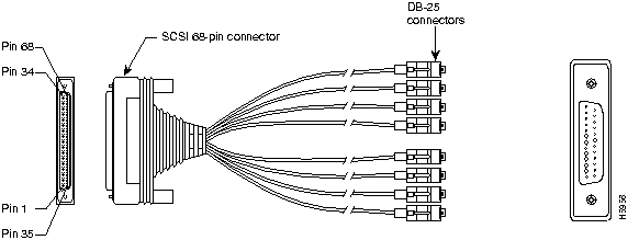
CAB-OCTAL-ASYNC cables use a 68-pin connector and breakout cable and provide eight RJ-45 rolled cable asynchronous ports on each 68-pin connector. You can connect each RJ-45 rolled cable asynchronous port to the console or Aux port of a device. The NM-16A or NM-32A high-density asynchronous network modules available for the 2600 and 3600 Series Routers can use this cable. For more information on cabling, refer to Serial Cable Guide and Cabling Guide for RJ-45 Console and AUX Ports.
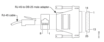
Note: The asynchronous ports from the 68-pin connector are data terminal equipment (DTE) devices. DTE to DTE devices require a rolled (null modem) cable. DTE to data circuit-terminating equipment (DCE) devices require a straight-through cable. Since the CAB-OCTAL-ASYNC cable is itself rolled, you can connect each cable directly to the console ports of devices with RJ-45 interfaces. However, if the console port of the device to which you are connecting is a 25-pin interface (DCE), use the RJ-45 to 25-pin adapter (product number CAB-5MODCM=) marked "Modem" (to reverse the "roll") to complete the connection. Remember, if you need to increase the reach of the CAB-OCTAL-ASYNC cable, use a straight-through RJ-45 cable for the extension.
Port types for console and auxiliary ports on Cisco routers and switches are:
| Interface Type | DB25 Interface | RJ-45 Interface |
|---|---|---|
| Console | DCE | DTE |
| AUX | DTE | DTE |
Cable Pinout

| RJ45 Plug # | Pin # | Signal Name | J1 Pin # |
|---|---|---|---|
| 1 | 8 | RTS | 2 |
| 7 | DTR | 36 | |
| 6 | TXC | 3 | |
| 5 | TXC GND | 37 | |
| 4 | RXC GND | 4 | |
| 3 | RXC | 38 | |
| 2 | DSR | 5 | |
| 1 | CTS | 39 | |
| 2 | 8 | RTS | 6 |
| 7 | DTR | 40 | |
| 6 | TXC | 7 | |
| 5 | TXC GND | 41 | |
| 4 | RXC GND | 8 | |
| 3 | RXC | 42 | |
| 2 | DSR | 9 | |
| 1 | CTS | 43 | |
| 3 | 8 | RTS | 10 |
| 7 | DTR | 44 | |
| 6 | TXC | 11 | |
| 5 | TXC GND | 45 | |
| 4 | RXC GND | 12 | |
| 3 | RXC | 46 | |
| 2 | DSR | 13 | |
| 1 | CTS | 47 | |
| 4 | 8 | RTS | 14 |
| 7 | DTR | 48 | |
| 6 | TXC | 15 | |
| 5 | TXC GND | 49 | |
| 4 | RXC GND | 16 | |
| 3 | RXC | 50 | |
| 2 | DSR | 17 | |
| 1 | CTS | 51 | |
| 5 | 8 | RTS | 18 |
| 7 | DTR | 52 | |
| 6 | TXC | 19 | |
| 5 | TXC GND | 53 | |
| 4 | RXC GND | 20 | |
| 3 | RXC | 54 | |
| 2 | DSR | 21 | |
| 1 | CTS | 55 | |
| 6 | 8 | RTS | 22 |
| 7 | DTR | 56 | |
| 6 | TXC | 23 | |
| 5 | TXC GND | 57 | |
| 4 | RXC GND | 24 | |
| 3 | RXC | 58 | |
| 2 | DSR | 25 | |
| 1 | CTS | 59 | |
| 7 | 8 | RTS | 26 |
| 7 | DTR | 60 | |
| 6 | TXC | 27 | |
| 5 | TXC GND | 61 | |
| 4 | RXC GND | 28 | |
| 3 | RXC | 62 | |
| 2 | DSR | 29 | |
| 1 | CTS | 63 | |
| 8 | 8 | RTS | 30 |
| 7 | DTR | 64 | |
| 6 | TXC | 31 | |
| 5 | TXC GND | 65 | |
| 4 | RXC GND | 32 | |
| 3 | RXC | 66 | |
| 2 | DSR | 33 | |
| 1 | CTS | 67 |
This cable has a male DB-68 (SCSI II) connector on the Cisco end, and eight RJ-45 connectors on the network end that can connect into eight DB-25 modular adapters if the end device has a 25-pin port.

Related Information
Revision History
| Revision | Publish Date | Comments |
|---|---|---|
1.0 |
09-Sep-2005 |
Initial Release |
Contact Cisco
- Open a Support Case

- (Requires a Cisco Service Contract)
 Feedback