FTD-Schnittstellen im Inline-Pair-Modus konfigurieren
Download-Optionen
-
ePub (840.0 KB)
In verschiedenen Apps auf iPhone, iPad, Android, Sony Reader oder Windows Phone anzeigen
Inklusive Sprache
In dem Dokumentationssatz für dieses Produkt wird die Verwendung inklusiver Sprache angestrebt. Für die Zwecke dieses Dokumentationssatzes wird Sprache als „inklusiv“ verstanden, wenn sie keine Diskriminierung aufgrund von Alter, körperlicher und/oder geistiger Behinderung, Geschlechtszugehörigkeit und -identität, ethnischer Identität, sexueller Orientierung, sozioökonomischem Status und Intersektionalität impliziert. Dennoch können in der Dokumentation stilistische Abweichungen von diesem Bemühen auftreten, wenn Text verwendet wird, der in Benutzeroberflächen der Produktsoftware fest codiert ist, auf RFP-Dokumentation basiert oder von einem genannten Drittanbieterprodukt verwendet wird. Hier erfahren Sie mehr darüber, wie Cisco inklusive Sprache verwendet.
Informationen zu dieser Übersetzung
Cisco hat dieses Dokument maschinell übersetzen und von einem menschlichen Übersetzer editieren und korrigieren lassen, um unseren Benutzern auf der ganzen Welt Support-Inhalte in ihrer eigenen Sprache zu bieten. Bitte beachten Sie, dass selbst die beste maschinelle Übersetzung nicht so genau ist wie eine von einem professionellen Übersetzer angefertigte. Cisco Systems, Inc. übernimmt keine Haftung für die Richtigkeit dieser Übersetzungen und empfiehlt, immer das englische Originaldokument (siehe bereitgestellter Link) heranzuziehen.
Inhalt
Einleitung
Dieses Dokument beschreibt die Konfiguration, Verifizierung und den Betrieb einer Inline-Pair-Schnittstelle auf einer FirePOWER Threat Defense (FTD)-Appliance.
Voraussetzungen
Anforderungen
Es gibt keine spezifischen Anforderungen für dieses Dokument.
Verwendete Komponenten
Die Informationen in diesem Dokument basierend auf folgenden Software- und Hardware-Versionen:
- Firepower 4112 FTD (Code 7.x)
- FirePOWER Management Center (FMC) (Code 7.x)
Die Informationen in diesem Dokument beziehen sich auf Geräte in einer speziell eingerichteten Testumgebung. Alle Geräte, die in diesem Dokument benutzt wurden, begannen mit einer gelöschten (Nichterfüllungs) Konfiguration. Wenn Ihr Netzwerk in Betrieb ist, stellen Sie sicher, dass Sie die möglichen Auswirkungen aller Befehle kennen.
Verwandte Produkte
Dieses Dokument kann auch mit folgenden Hardware- und Softwareversionen verwendet werden:
- FPR1000, FPR2100, FPR4100, FPR9300
- Secure Firewall der Serien 3100 und 4200
- vFTD
- FTD-Softwarecode 6.2.x und höher
Hintergrundinformationen
FTD ist ein einheitliches Software-Image, das aus zwei Haupt-Engines besteht:
- LINA-Engine
- Snort-Engine
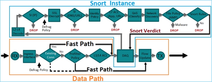
Diese Abbildung zeigt, wie die beiden Engines interagieren:
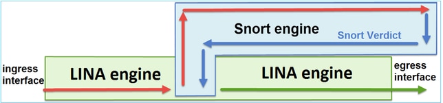
- Ein Paket gelangt an die Eingangsschnittstelle, und es wird von der LINA-Engine verarbeitet.
- Wenn dies nach der FTD-Richtlinie erforderlich ist, wird das Paket von der Snort-Engine geprüft.
- Die Snort-Engine gibt ein Urteil für das Paket zurück.
- Die LINA-Engine verwirft oder leitet das Paket basierend auf dem Urteil von Snort weiter.
FTD bietet zwei Bereitstellungsmodi und sechs Schnittstellenmodi, wie im Bild gezeigt:
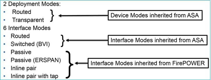
Anmerkung: Sie können die Schnittstellenmodi auf einer FTD-Einheit kombinieren.
Im Folgenden finden Sie einen allgemeinen Überblick über die verschiedenen FTD-Bereitstellungs- und Schnittstellenmodi:
| FTD-Schnittstellenmodus |
FTD-Bereitstellungsmodus |
Beschreibung |
Datenverkehr kann verworfen werden |
| Geroutet |
Geroutet |
Vollständige LINA-Engine- und Snort-Engine-Prüfungen. |
Ja |
| Geschaltet |
Transparent |
Vollständige LINA-Engine- und Snort-Engine-Prüfungen. |
Ja |
| Inline-Paar |
Geroutet oder transparent |
Partielle LINA-Engine- und vollständige Snort-Engine-Prüfungen. |
Ja |
| Inline-Paar mit Tap |
Geroutet oder transparent |
Partielle LINA-Engine- und vollständige Snort-Engine-Prüfungen. |
Nein |
| Passive |
Geroutet oder transparent |
Partielle LINA-Engine- und vollständige Snort-Engine-Prüfungen. |
Nein |
| Passiv (ERSPAN) |
Geroutet |
Partielle LINA-Engine- und vollständige Snort-Engine-Prüfungen. |
Nein |
Konfigurieren der Inline-Paarschnittstelle auf FTD
Netzwerkdiagramm
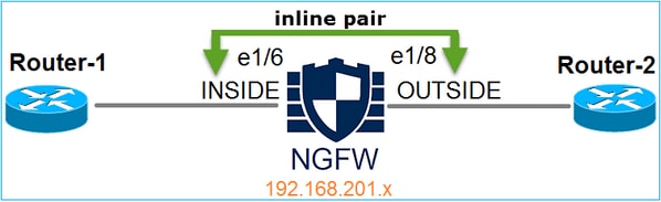
Anforderung
Konfigurieren Sie die physischen Schnittstellen e1/3 und e1/4 im Inline-Paarmodus gemäß den folgenden Anforderungen:
| Schnittstelle | e1/3 | e1/4 |
| Name | INNEN | AUSSEN |
| Sicherheitszone | INNENBEREICH | EXTERNE_ZONE |
| Name des Inline-Satzes | Inline-Paar-1 | |
| Inline-Set-MTU | 1500 | |
| Verknüpfungsstatus propagieren | Aktiviert |
Lösung
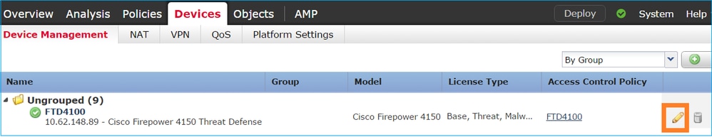
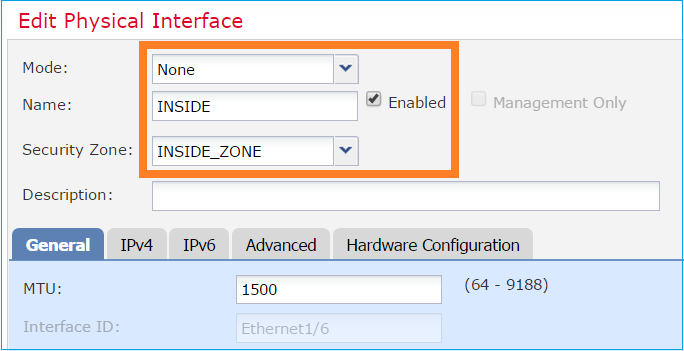
Schritt 1: Um die einzelnen Schnittstellen zu konfigurieren, navigieren Sie zu Geräte > Gerätemanagement, wählen Sie das entsprechende Gerät aus, und wählen Sie Bearbeiten:
Geben Sie als Nächstes Name an, und markieren Sie Enabled (Aktiviert) für die Schnittstelle, wie im Bild dargestellt.
Anmerkung: Der Name ist der Name der Schnittstelle.
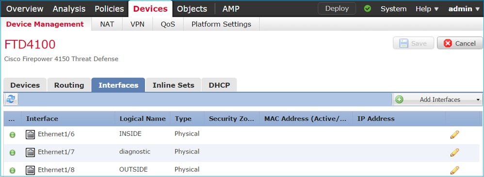
Ähnlich für Schnittstelle Ethernet1/4. Das Endergebnis wird angezeigt:
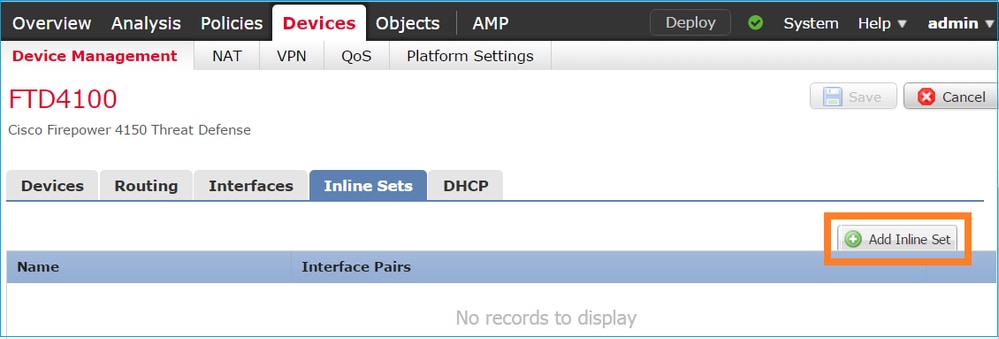
Schritt 2: Konfigurieren des Inline-Paars
Navigieren Sie zu Inline Sets > Add Inline Set (Inline Set hinzufügen), wie im Bild dargestellt.
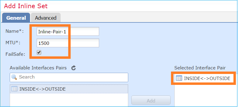
Schritt 3: Konfigurieren Sie die allgemeinen Einstellungen gemäß den im Bild gezeigten Anforderungen.
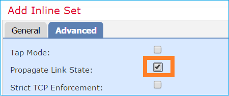
Schritt 4: Aktivieren Sie die Option Link-Zustand propagieren in den erweiterten Einstellungen, wie im Bild gezeigt.
Durch die Link-State-Propagierung wird die zweite Schnittstelle im Inline-Schnittstellenpaar automatisch deaktiviert, wenn eine der Schnittstellen im Inline-Set ausfällt.
Schritt 5: Speichern der Änderungen und Bereitstellen.
Überprüfung
Verwenden Sie diesen Abschnitt, um zu überprüfen, ob Ihre Konfiguration ordnungsgemäß funktioniert.
Überprüfen der Inline-Paar-Konfiguration über die FTD-CLI
Lösung
Melden Sie sich bei der FTD-CLI an, und überprüfen Sie die Inline-Paar-Konfiguration:
firepower# show inline-set

Inline-set Inline-Pair-1
  Mtu is 1500 bytes
  Fail-open for snort down is on
  Fail-open for snort busy is off
  Tap mode is off
  Propagate-link-state option is on
  hardware-bypass mode is disabled
  Interface-Pair[1]:
    Interface: Ethernet1/4 "OUTSIDE"
      Current-Status: UP
    Interface: Ethernet1/3 "INSIDE"
      Current-Status: UP
    Bridge Group ID: 507
Anmerkung: Die Bridge-Gruppen-ID ist ein anderer Wert als 0. Wenn der Tap-Modus aktiviert ist, ist er 0.
Informationen zu Schnittstelle und Name:
firepower# show nameif
Interface       Name             Security
Ethernet1/1     management        0
Ethernet1/3     INSIDE            0
Ethernet1/4     OUTSIDE           0
Überprüfen Sie den Schnittstellenstatus:
firepower# show interface ip brief
Interface             IP-Address    OK? Method Status Protocol
Internal-Control0/0   unassigned    YES unset  up     up
Internal-Data0/0      unassigned    YES unset  up     up
Internal-Data0/1      unassigned    YES unset  up     up
Internal-Data0/2      169.254.1.1   YES unset  up     up
Internal-Data0/3      unassigned    YES unset  up     up
Internal-Data0/4      unassigned    YES unset  down   up
Ethernet1/1           203.0.113.130 YES unset  up     up
Ethernet1/3           unassigned    YES unset  up     up
Ethernet1/4           unassigned    YES unset  up     up
Überprüfen Sie die Informationen der physischen Schnittstelle:
firepower# show interface e1/3
Interface Ethernet1/3 "INSIDE", is up, line protocol is up
  Hardware is EtherSVI, BW 1000 Mbps, DLY 10 usec
           MAC address ac4a.670e.641e, MTU 1500
           IPS Interface-Mode: inline, Inline-Set: Inline-Pair-1
           IP address unassigned
  Traffic Statistics for "INSIDE":
           170 packets input, 12241 bytes
            41 packets output, 7881 bytes
             9 packets dropped
      1 minute input rate 0 pkts/sec, 37 bytes/sec
      1 minute output rate 0 pkts/sec, 19 bytes/sec
      1 minute drop rate, 0 pkts/sec
      5 minute input rate 0 pkts/sec, 34 bytes/sec
      5 minute output rate 0 pkts/sec, 23 bytes/sec
      5 minute drop rate, 0 pkts/sec
FTD-Inline-Paar-Schnittstellenbetrieb überprüfen
In diesem Abschnitt werden die folgenden Verifizierungsprüfungen zur Verifizierung des Inline-Pair-Betriebs beschrieben:
- Verifikation 1. Mit dem Packet-Tracer.
- Überprüfung 2. Aktivieren Sie die Erfassung mit Trace, und senden Sie ein TCP-Synchronisierungs-/Bestätigungspaket (SYN/ACK) über das Inline-Paar.
- Überprüfung 3. Überwachen des FTD-Datenverkehrs mithilfe des Firewall-Engine-Debugging
- Überprüfung 4. Überprüfen der Funktion für die Link-State-Propagierung
- Verifizierung 5. Konfigurieren der statischen Network Address Translation (NAT)
Lösung
Überblick über die Architektur
Wenn zwei FTD-Schnittstellen im Inline-Pair-Modus betrieben werden, wird ein Paket verarbeitet, wie im Bild gezeigt.
Anmerkung: Nur physische Schnittstellen können Mitglieder eines Inline-Paarsatzes sein.
Theorie der Grundlagen
- Wenn Sie ein physisches Inline-Paar 2 konfigurieren, werden die Schnittstellen intern überbrückt.
- Ähnlich wie das klassische Inline Intrusion Prevention System (IPS).
- Verfügbar im Routed- oder Transparent-Bereitstellungsmodus.
- Die meisten LINA-Engine-Funktionen (NAT, Routing usw.) sind nicht für Datenflüsse verfügbar, die ein Inline-Paar durchlaufen.
- Transitverkehr kann unterbrochen werden.
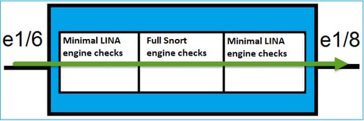
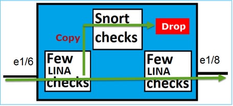
- Einige LINA-Modulprüfungen werden zusammen mit vollständigen Snort-Modulprüfungen angewendet.
Der letzte Punkt kann wie im Bild dargestellt dargestellt dargestellt werden:
Verifizierung 1. Mit dem Einsatz von Packet-Tracer
Die Paketverfolgungsausgabe, die ein Paket emuliert, das das Inline-Paar mit den folgenden wichtigen Punkten durchquert:
firepower# packet-tracer input INSIDE tcp 192.168.201.50 1111 192.168.202.50 80

Phase: 1
Type: NGIPS-MODE
Subtype: ngips-mode
Result: ALLOW
Elapsed time: 11834 ns
Config:
Additional Information:
The flow ingressed an interface configured for NGIPS mode and NGIPS services will be applied

Phase: 2
Type: ACCESS-LIST
Subtype:
Result: ALLOW
Elapsed time: 11834 ns
Config:
access-group CSM_FW_ACL_ global
access-list CSM_FW_ACL_ advanced permit ip host 192.168.201.50 host 192.168.202.50 rule-id 268451044
access-list CSM_FW_ACL_ remark rule-id 268451044: ACCESS POLICY: mzafeiro_2m - Mandatory
access-list CSM_FW_ACL_ remark rule-id 268451044: L7 RULE: New-Rule-#1303-ALLOW
Additional Information:
This packet will be sent to snort for additional processing where a verdict will be reached

Phase: 3
Type: NGIPS-EGRESS-INTERFACE-LOOKUP
Subtype: Resolve Egress Interface
Result: ALLOW
Elapsed time: 2440 ns
Config:
Additional Information:
Ingress interface INSIDE is in NGIPS inline mode.
Egress interface OUTSIDE is determined by inline-set configuration

Phase: 4
Type: FLOW-CREATION
Subtype:
Result: ALLOW
Elapsed time: 68320 ns
Config:
Additional Information:
New flow created with id 1801, packet dispatched to next module

Phase: 5
Type: EXTERNAL-INSPECT
Subtype:
Result: ALLOW
Elapsed time: 18056 ns
Config:
Additional Information:
Application: 'SNORT Inspect'

Phase: 6
Type: SNORT
Subtype: identity
Result: ALLOW
Elapsed time: 13668 ns
Config:
Additional Information:
user id: no auth, realm id: 0, device type: 0, auth type: invalid, auth proto: basic, username: none, AD domain: none,
src sgt: 0, src sgt type: unknown, dst sgt: 0, dst sgt type: unknown, abp src: none, abp dst: none, location: none

Phase: 7
Type: SNORT
Subtype: firewall
Result: ALLOW
Elapsed time: 67770 ns
Config:
Network 0, Inspection 0, Detection 0, Rule ID 268451044
Additional Information:
Starting rule matching, zone -1 -> -1, geo 0 -> 0, vlan 0, src sgt: 0, src sgt type: unknown, dst sgt: 0, dst sgt type: unknown, user 9999997, no url or host, no xff
Matched rule ids 268451044 - Allow

Phase: 8
Type: SNORT
Subtype: appid
Result: ALLOW
Elapsed time: 11002 ns
Config:
Additional Information:
service: (0), client: (0), payload: (0), misc: (0)

Result:
input-interface: INSIDE(vrfid:0)
input-status: up
input-line-status: up
output-interface: OUTSIDE(vrfid:0)
output-status: up
output-line-status: up
Action: allow
Time Taken: 204924 ns
Überprüfung 2. Senden von TCP SYN/ACK-Paketen über Inline-Paar
Sie können TCP-SYN/ACK-Pakete mithilfe eines Pakets generieren, das ein Dienstprogramm wie Scapy erstellt. Diese Syntax generiert 3 Pakete mit aktivierten SYN/ACK-Flags:
root@KALI:~# scapy
INFO: Can't import python gnuplot wrapper . Won't be able to plot.
WARNING: No route found for IPv6 destination :: (no default route?)
Welcome to Scapy (2.2.0)
>>> conf.iface='eth0'
>>> packet = IP(dst="192.168.201.60")/TCP(flags="SA",dport=80)
>>> syn_ack=[]
>>> for i in range(0,3): # Send 3 packets
...  syn_ack.extend(packet)
...
>>> send(syn_ack)
Aktivieren Sie diese Erfassung für FTD CLI, und senden Sie einige TCP SYN/ACK-Pakete:
firepower# capture CAPI interface INSIDE trace match ip host 192.168.201.60 any
firepower# capture CAPO interface OUTSIDE match ip host 192.168.201.60 any
Die Erfassung zeigt, dass die 3 SYN/ACK-Pakete das FTD durchlaufen:
firepower# show capture CAPI

3 packets captured

1: 09:20:18.206440 192.168.201.50.20 > 192.168.201.60.80: S 0:0(0) ack 0 win 8192
2: 09:20:18.208180 192.168.201.50.20 > 192.168.201.60.80: S 0:0(0) ack 0 win 8192
3: 09:20:18.210026 192.168.201.50.20 > 192.168.201.60.80: S 0:0(0) ack 0 win 8192
3 packets shown
firepower# show capture CAPO

3 packets captured

1: 09:20:18.206684 192.168.201.50.20 > 192.168.201.60.80: S 0:0(0) ack 0 win 8192
2: 09:20:18.208210 192.168.201.50.20 > 192.168.201.60.80: S 0:0(0) ack 0 win 8192
3: 09:20:18.210056 192.168.201.50.20 > 192.168.201.60.80: S 0:0(0) ack 0 win 8192
3 packets shown
Der Trace des ersten Capture-Pakets enthüllt einige zusätzliche Informationen wie das Snort-Engine-Urteil:
firepower# show capture CAPI packet-number 1 trace

3 packets captured

1: 09:20:18.206440 192.168.201.50.20 > 192.168.201.60.80: S 0:0(0) ack 0 win 8192
Phase: 1
Type: NGIPS-MODE
Subtype: ngips-mode
Result: ALLOW
Elapsed time: 5978 ns
Config:
Additional Information:
The flow ingressed an interface configured for NGIPS mode and NGIPS services will be applied

Phase: 2
Type: ACCESS-LIST
Subtype:
Result: ALLOW
Elapsed time: 5978 ns
Config:
access-group CSM_FW_ACL_ global
access-list CSM_FW_ACL_ advanced permit ip host 192.168.201.50 object-group FMC_INLINE_dst_rule_268451044 rule-id 268451044
access-list CSM_FW_ACL_ remark rule-id 268451044: ACCESS POLICY: mzafeiro_2m - Mandatory
access-list CSM_FW_ACL_ remark rule-id 268451044: L7 RULE: New-Rule-#1303-ALLOW
object-group network FMC_INLINE_dst_rule_268451044
network-object 192.168.202.50 255.255.255.255
network-object 192.168.201.60 255.255.255.255
Additional Information:
This packet will be sent to snort for additional processing where a verdict will be reached

Phase: 3
Type: NGIPS-EGRESS-INTERFACE-LOOKUP
Subtype: Resolve Egress Interface
Result: ALLOW
Elapsed time: 1952 ns
Config:
Additional Information:
Ingress interface INSIDE is in NGIPS inline mode.
Egress interface OUTSIDE is determined by inline-set configuration

Phase: 4
Type: FLOW-CREATION
Subtype:
Result: ALLOW
Elapsed time: 45872 ns
Config:
Additional Information:
New flow created with id 1953, packet dispatched to next module

Phase: 5
Type: EXTERNAL-INSPECT
Subtype:
Result: ALLOW
Elapsed time: 18544 ns
Config:
Additional Information:
Application: 'SNORT Inspect'

Phase: 6
Type: SNORT
Subtype: identity
Result: ALLOW
Elapsed time: 25182 ns
Config:
Additional Information:
user id: no auth, realm id: 0, device type: 0, auth type: invalid, auth proto: basic, username: none, AD domain: none,
src sgt: 0, src sgt type: unknown, dst sgt: 0, dst sgt type: unknown, abp src: none, abp dst: none, location: none

Phase: 7
Type: SNORT
Subtype: firewall
Result: ALLOW
Elapsed time: 50924 ns
Config:
Network 0, Inspection 0, Detection 0, Rule ID 268451044
Additional Information:
Starting rule matching, zone -1 -> -1, geo 0 -> 0, vlan 0, src sgt: 0, src sgt type: unknown, dst sgt: 0, dst sgt type: unknown, user 9999997, no url or host, no xff
Matched rule ids 268451044 - Allow

Phase: 8
Type: SNORT
Subtype: appid
Result: ALLOW
Elapsed time: 17722 ns
Config:
Additional Information:
service: (0), client: (0), payload: (0), misc: (0)

Result:
input-interface: INSIDE(vrfid:0)
input-status: up
input-line-status: up
output-interface: OUTSIDE(vrfid:0)
output-status: up
output-line-status: up
Action: allow
Time Taken: 172152 ns


1 packet shown
Die Ablaufverfolgung des zweiten erfassten Pakets zeigt, dass das Paket mit einer aktuellen Verbindung übereinstimmt, sodass es die ACL-Prüfung umgeht, aber dennoch von der Snort-Engine überprüft wird:
firepower# show capture CAPI packet-number 2 trace

3 packets captured

2: 09:20:18.208180 192.168.201.50.20 > 192.168.201.60.80: S 0:0(0) ack 0 win 8192
Phase: 1
Type: FLOW-LOOKUP
Subtype:
Result: ALLOW
Elapsed time: 1952 ns
Config:
Additional Information:
Found flow with id 1953, using existing flow

Phase: 2
Type: EXTERNAL-INSPECT
Subtype:
Result: ALLOW
Elapsed time: 7320 ns
Config:
Additional Information:
Application: 'SNORT Inspect'

Phase: 3
Type: SNORT
Subtype: appid
Result: ALLOW
Elapsed time: 1860 ns
Config:
Additional Information:
service: (0), client: (0), payload: (0), misc: (0)

Result:
input-interface: INSIDE(vrfid:0)
input-status: up
input-line-status: up
Action: allow
Time Taken: 11132 ns


1 packet shown
Überprüfung 3. Firewall-Engine-Debugging für zulässigen Datenverkehr
Das Debugging der Firewall-Engine wird auf bestimmten Komponenten der FTD Snort Engine ausgeführt, z. B. auf der Grundlage der Zugriffskontrollrichtlinie, wie im Bild gezeigt:
Wenn Sie die TCP SYN/ACK-Pakete über Inline Pair senden, sehen Sie in der Debug-Ausgabe Folgendes:
> system support firewall-engine-debug

Please specify an IP protocol: tcp
Please specify a client IP address:
Please specify a client port:
Please specify a server IP address: 192.168.201.60
Please specify a server port: 80
Monitoring firewall engine debug messages

192.168.201.60-80 > 192.168.201.50-20 6 AS 4 I 12 New session
192.168.201.60-80 > 192.168.201.50-20 6 AS 4 I 12 using HW or preset rule order 3, id 268438528 action Allow and prefilter rule 0
192.168.201.60-80 > 192.168.201.50-20 6 AS 4 I 12 allow action
192.168.201.60-80 > 192.168.201.50-20 6 AS 4 I 12 Deleting session
Überprüfung 4. Überprüfung der Link-State-Propagierung
Aktivieren Sie das Pufferprotokoll auf FTD, und fahren Sie den mit der e1/4-Schnittstelle verbundenen Switch-Port herunter. In der FTD CLI müssen Sie sehen, dass beide Schnittstellen ausgefallen sind:
firepower# show interface ip brief
Interface               IP-Address    OK? Method Status     Protocol
Internal-Control0/0     unassigned    YES unset  up         up
Internal-Data0/0        unassigned    YES unset  up         up
Internal-Data0/1        unassigned    YES unset  up         up
Internal-Data0/2        169.254.1.1   YES unset  up         up
Internal-Data0/3        unassigned    YES unset  up         up
Internal-Data0/4        unassigned    YES unset  down       up
Ethernet1/1             203.0.113.130 YES unset  up         up
Ethernet1/3             unassigned    YES unset  admin down down
Ethernet1/4             unassigned    YES unset  down       down
Die FTD-Protokolle zeigen Folgendes:
firepower# show log
...
May 28 2024 07:35:10: %FTD-4-411002: Line protocol on Interface Ethernet1/4, changed state to down
May 28 2024 07:35:10: %FTD-4-411004: Interface INSIDE, changed state to administratively down
May 28 2024 07:35:10: %FTD-4-411004: Interface Ethernet1/3, changed state to administratively down
May 28 2024 07:35:10: %FTD-4-812005: Link-State-Propagation activated on inline-pair due to failure of interface Ethernet1/4(OUTSIDE) bringing down pair interface Ethernet1/3(INSIDE)
May 28 2024 07:35:10: %FTD-4-411002: Line protocol on Interface Ethernet1/3, changed state to down
Der Inline-Set-Status zeigt den Status der beiden Schnittstellenmember an:
firepower# show inline-set

Inline-set Inline-Pair-1
  Mtu is 1500 bytes
  Fail-open for snort down is on
  Fail-open for snort busy is off
  Tap mode is off
  Propagate-link-state option is on
  hardware-bypass mode is disabled
    Interface-Pair[1]:
    Interface: Ethernet1/4 "OUTSIDE"
      Current-Status: Down(Propagate-Link-State-Activated)
    Interface: Ethernet1/3 "INSIDE"
      Current-Status: Down(Administrative-Down-By-Propagate-Link-State)
Bridge Group ID: 507
Beachten Sie den Unterschied im Status der beiden Schnittstellen:
firepower# show interface e1/3
Interface Ethernet1/3 "INSIDE", is admin down, line protocol is down
  Hardware is EtherSVI, BW 1000 Mbps, DLY 10 usec
        MAC address ac4a.670e.641e, MTU 1500
        IPS Interface-Mode: inline, Inline-Set: Inline-Pair-1
        Administrative-Down-By-Propagate-Link-State
        IP address unassigned
  Traffic Statistics for "INSIDE":
        2400 packets input, 165873 bytes
        1822 packets output, 178850 bytes
        17 packets dropped
      1 minute input rate 0 pkts/sec,  0 bytes/sec
      1 minute output rate 0 pkts/sec,  0 bytes/sec
      1 minute drop rate, 0 pkts/sec
      5 minute input rate 0 pkts/sec,  32 bytes/sec
      5 minute output rate 0 pkts/sec,  57 bytes/sec
      5 minute drop rate, 0 pkts/sec
firepower# show interface e1/4
Interface Ethernet1/4 "OUTSIDE", is down, line protocol is down
  Hardware is EtherSVI, BW 1000 Mbps, DLY 10 usec
        MAC address ac4a.670e.640e, MTU 1500
        IPS Interface-Mode: inline, Inline-Set: Inline-Pair-1
        Propagate-Link-State-Activated
        IP address unassigned
  Traffic Statistics for "OUTSIDE":
        1893 packets input, 158046 bytes
        2386 packets output, 213997 bytes
        67 packets dropped
      1 minute input rate 0 pkts/sec,  0 bytes/sec
      1 minute output rate 0 pkts/sec,  0 bytes/sec
      1 minute drop rate, 0 pkts/sec
      5 minute input rate 0 pkts/sec,  51 bytes/sec
      5 minute output rate 0 pkts/sec,  39 bytes/sec
      5 minute drop rate, 0 pkts/sec
Nach der erneuten Aktivierung des Switch-Ports zeigen die FTD-Protokolle Folgendes an:
May 28 2024 07:38:04: %FTD-4-411001: Line protocol on Interface Ethernet1/4, changed state to up
May 28 2024 07:38:04: %FTD-4-411003: Interface Ethernet1/3, changed state to administratively up
May 28 2024 07:38:04: %FTD-4-411003: Interface INSIDE, changed state to administratively up
May 28 2024 07:38:04: %FTD-4-812006: Link-State-Propagation de-activated on inline-pair due to recovery of interface Ethernet1/4(OUTSIDE) bringing up pair interface Ethernet1/3(INSIDE)
May 28 2024 07:38:05: %FTD-4-411002: Line protocol on Interface Ethernet1/4, changed state to down
Überprüfung 5. Konfigurieren der statischen NAT
Lösung
NAT wird nicht für Schnittstellen unterstützt, die im Inline-, Inline-Tap- oder Passivmodus betrieben werden:
Konfigurationsleitfaden für FirePOWER Management Center, Version 6.0.1
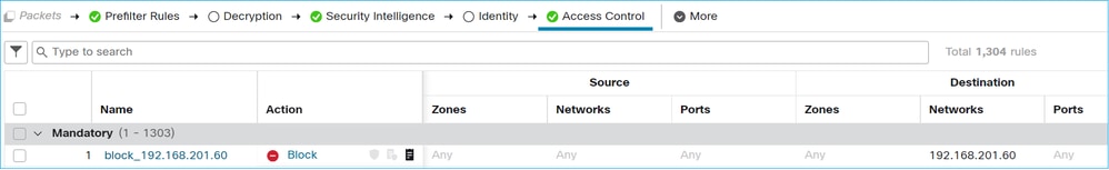
Paket im Inline-Paar-Schnittstellenmodus blockieren
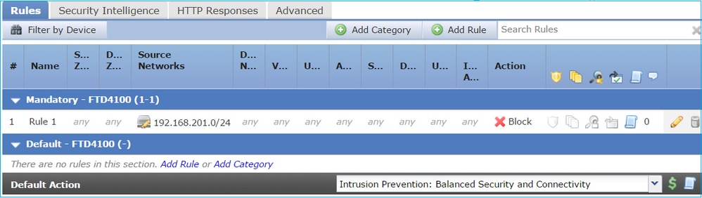
Erstellen Sie eine Blockierungsregel, senden Sie Datenverkehr über das FTD-Inline-Paar, und beobachten Sie das Verhalten, wie im Bild dargestellt.
Lösung
Aktivieren Sie die Erfassung mit Trace, und senden Sie die SYN/ACK-Pakete über das FTD-Inline-Paar. Der Datenverkehr wird blockiert:
firepower# show capture
capture CAPI type raw-data trace interface INSIDE [Capturing - 270 bytes]
  match ip host 192.168.201.60 any
capture CAPO type raw-data interface OUTSIDE [Capturing - 0 bytes]
  match ip host 192.168.201.60 any
Im Trace ist zu sehen, dass das Paket von der FTD LINA-Engine verworfen und nicht an die FTD Snort-Engine weitergeleitet wurde.
firepower# show capture CAPI packet-number 1 trace

4 packets captured

   1: 09:41:54.562547       192.168.201.50.59144 > 192.168.201.60.80: S 3817586151:3817586151(0) win 64240 <mss 1460,sackOK,timestamp 2568467664 0,nop,wscale 7>
Phase: 1
Type: NGIPS-MODE
Subtype: ngips-mode
Result: ALLOW
Elapsed time: 10126 ns
Config:
Additional Information:
The flow ingressed an interface configured for NGIPS mode and NGIPS services will be applied

Phase: 2
Type: ACCESS-LIST
Subtype:
Result: DROP
Elapsed time: 10126 ns
Config:
access-group CSM_FW_ACL_ global
access-list CSM_FW_ACL_ advanced deny ip any host 192.168.201.60 rule-id 268451045 event-log flow-start
access-list CSM_FW_ACL_ remark rule-id 268451045: ACCESS POLICY: mzafeiro_2m - Mandatory
access-list CSM_FW_ACL_ remark rule-id 268451045: L4 RULE: block_192.168.201.60
Additional Information:

Result:
input-interface: INSIDE(vrfid:0)
input-status: up
input-line-status: up
Action: drop

Time Taken: 20252 ns

1 packet shown
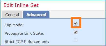
Konfiguration des Inline-Pair-Modus mit TAP
Aktivieren Sie den Tap-Modus für das Inline-Paar.
Lösung
Navigieren Sie zu Devices (Geräte) > Device Management (Geräteverwaltung) > Inline Sets (Inline-Sets) > Edit Inline Set (Inline-Set bearbeiten) > Advanced (Erweitert), und aktivieren Sie den Tap Mode (Tap-Modus), wie im Bild dargestellt.
Verifizierung
firepower# show inline-set

Inline-set Inline-Pair-1
  Mtu is 1500 bytes
  Fail-open for snort down is off
  Fail-open for snort busy is off
  Tap mode is on
  Propagate-link-state option is on
  hardware-bypass mode is disabled
  Interface-Pair[1]:
    Interface: Ethernet1/4 "OUTSIDE"
      Current-Status: UP
    Interface: Ethernet1/3 "INSIDE"
      Current-Status: UP
   Bridge Group ID: 0
Überprüfen des FTD-Inline-Paars mit Tap-Schnittstellenfunktion
Theorie der Grundlagen
- Wenn Sie ein Inline-Paar mit Tap konfigurieren, werden physische Schnittstellen intern überbrückt.
- Sie ist im Routed-Modus oder im Transparent-Bereitstellungsmodus verfügbar.
- Die meisten LINA-Engine-Funktionen (NAT, Routing usw.) sind nicht für Datenflüsse verfügbar, die das Inline-Paar durchlaufen.
- Der tatsächliche Datenverkehr kann nicht verworfen werden.
- Einige LINA-Engine-Prüfungen werden zusammen mit vollständigen Snort-Engine-Prüfungen auf eine Kopie des tatsächlichen Datenverkehrs angewendet.
Das Inline-Paar mit Tap Mode lässt den Transitverkehr nicht fallen. Mit der Spur eines Pakets bestätigt er dies:
> show capture CAPI packet-number 2 trace

3 packets captured

   2: 13:34:30.685084       192.168.201.50.20 > 192.168.201.60.80: S 0:0(0) win 8192
Phase: 1
Type: CAPTURE
Subtype:
Result: ALLOW
Config:
Additional Information:
MAC Access list

Phase: 2
Type: ACCESS-LIST
Subtype:
Result: ALLOW
Config:
Implicit Rule
Additional Information:
MAC Access list

Phase: 3
Type: NGIPS-MODE
Subtype: ngips-mode
Result: ALLOW
Config:
Additional Information:
The flow ingressed an interface configured for NGIPS mode and NGIPS services is applied

Phase: 4
Type: ACCESS-LIST
Subtype: log
Result: WOULD HAVE DROPPED
Config:
access-group CSM_FW_ACL_ global
access-list CSM_FW_ACL_ advanced deny ip 192.168.201.0 255.255.255.0 any rule-id 268441600 event-log flow-start
access-list CSM_FW_ACL_ remark rule-id 268441600: ACCESS POLICY: FTD4100 - Mandatory/1
access-list CSM_FW_ACL_ remark rule-id 268441600: L4 RULE: Rule 1
Additional Information:

Result:
input-interface: INSIDE
input-status: up
input-line-status: up
Action: Access-list would have dropped, but packet forwarded due to inline-tap


1 packet shown
>
Inline-Paar und EtherChannel
Sie können Inline-Paare mit Etherchannel auf zwei Arten konfigurieren:
- Etherchannel wird auf FTD terminiert.
- Etherchannel wird über FTD übertragen (erfordert FXOS-Code 2.3.1.3 und höher).
Etherchannel wird über FTD terminiert
Etherchannels auf SW-A:
SW-A# show etherchannel summary | i Po33|Po55
33     Po33(SU)        LACP      Gi3/11(P)
35     Po35(SU)        LACP      Gi2/33(P)
Etherchannels auf SW-B:
SW-B# show etherchannel summary | i Po33|Po55
33     Po33(SU)        LACP        Gi1/0/3(P)
55     Po55(SU)        LACP        Gi1/0/4(P)
Der Datenverkehr wird über den aktiven FTD weitergeleitet, wobei die MAC-Adresse ermittelt wird:
SW-B# show mac address-table address 0017.dfd6.ec00
          Mac Address Table
-------------------------------------------

Vlan    Mac Address       Type        Ports
----    -----------       --------    -----
 201    0017.dfd6.ec00    DYNAMIC     Po33
Total Mac Addresses for this criterion: 1
Das Inline-Set auf FTD:
FTD# show inline-set

Inline-set SET1
  Mtu is 1500 bytes
  Fail-open for snort down is on
  Fail-open for snort busy is off
  Tap mode is off
  Propagate-link-state option is off
  hardware-bypass mode is disabled
  Interface-Pair[1]:
    Interface: Port-channel3 "INSIDE"
      Current-Status: UP
    Interface: Port-channel5 "OUTSIDE"
      Current-Status: UP
    Bridge Group ID: 775
Anmerkung: Bei einem FTD-Failover-Ereignis hängt der Ausfall des Datenverkehrs hauptsächlich von der Zeit ab, die die Switches benötigen, um die MAC-Adresse des Remote-Peers zu ermitteln.
Etherchannel durch FTD
Etherchannels auf SW-A:
SW-A# show etherchannel summary | i Po33|Po55
33     Po33(SU)        LACP      Gi3/11(P)
55     Po55(SD)        LACP      Gi3/7(I)
Die LACP-Pakete werden über den Standby-FTD blockiert:
FTD# capture ASP type asp-drop fo-standby
FTD# show capture ASP | i 0180.c200.0002
  29: 15:28:32.658123       a0f8.4991.ba03 0180.c200.0002 0x8809 Length: 124
  70: 15:28:47.248262       f0f7.556a.11e2 0180.c200.0002 0x8809 Length: 124
Etherchannels auf SW-B:
SW-B# show etherchannel summary | i Po33|Po55
33     Po33(SU)        LACP        Gi1/0/3(P)
55     Po55(SD)        LACP        Gi1/0/4(s)
Der Datenverkehr wird über den aktiven FTD weitergeleitet, wobei die MAC-Adresse ermittelt wird:
SW-B# show mac address-table address 0017.dfd6.ec00
          Mac Address Table
-------------------------------------------

Vlan    Mac Address       Type        Ports
----    -----------       --------    -----
 201    0017.dfd6.ec00    DYNAMIC     Po33
Total Mac Addresses for this criterion: 1
Das Inline-Set auf FTD:
FTD# show inline-set

Inline-set SET1
  Mtu is 1500 bytes
  Fail-open for snort down is on
  Fail-open for snort busy is off
  Tap mode is off
  Propagate-link-state option is off
  hardware-bypass mode is disabled
  Interface-Pair[1]:
    Interface: Ethernet1/3 "INSIDE"
      Current-Status: UP
    Interface: Ethernet1/5 "OUTSIDE"
      Current-Status: UP
    Bridge Group ID: 519
Vorsicht: In diesem Szenario hängt die Konvergenzzeit bei einem FTD-Failover-Ereignis hauptsächlich von der Etherchannel-LACP-Aushandlung und der Dauer des Ausfalls ab, der sehr viel länger sein kann. Wenn der Etherchannel-Modus EIN (kein LACP) ist, hängt die Konvergenzzeit vom MAC-Adressen-Learning ab.
Fehlerbehebung
Für diese Konfiguration sind derzeit keine spezifischen Informationen verfügbar.
Vergleich: Inline-Paar und Inline-Paar mit Tap
| Inline-Paar |
Inline-Paar mit Tap |
|
| Inline-Set anzeigen |
> Inline-Set anzeigen |
> Inline-Set anzeigen > |
| show interface |
> Schnittstelle e1/6 anzeigen |
> Schnittstelle e1/6 anzeigen |
| So behandeln Sie Pakete mit Blockregel |
> Capture-CAPI-Paketnummer 1-Ablaufverfolgung anzeigen |
> Capture-CAPI-Paketnummer 1-Ablaufverfolgung anzeigen |
Zusammenfassung
- Wenn Sie den Inline-Pair-Modus verwenden, durchläuft das Paket hauptsächlich die FTD Snort-Engine.
- TCP-Verbindungen werden im TCP-Status-Umgehungsmodus behandelt.
- Aus Sicht der FTD LINA-Engine wird eine ACL-Richtlinie angewendet.
- Wenn der Inline-Paarmodus verwendet wird, können Pakete blockiert werden, da sie inline verarbeitet werden.
- Wenn der Tap Mode (Tap-Modus) aktiviert ist, wird eine Kopie des Pakets geprüft und intern verworfen, während der tatsächliche Datenverkehr unverändert über FTD läuft.
Zugehörige Informationen
Revisionsverlauf
| Überarbeitung | Veröffentlichungsdatum | Kommentare |
|---|---|---|
3.0 |
18-Nov-2024 |
Cisco Internal Information Box wurde entfernt, da der Link nicht gefunden wurde.
Aktualisierte Einführung, Alternativer Text und Formatierung. |
2.0 |
28-Apr-2023 |
Rezertifizierung |
1.0 |
18-Oct-2017 |
Erstveröffentlichung |
Beiträge von Cisco Ingenieuren
- Mikis ZafeiroudisTechnical Consulting Engineer
- Dinkar SharmaTechnical Consulting Engineer
 Feedback
Cisco kontaktieren
- Eine Supportanfrage öffnen

- (Erfordert einen Cisco Servicevertrag)