Fehlerbehebung: Firepower Threat Defense Routing
Download-Optionen
-
ePub (4.0 MB)
In verschiedenen Apps auf iPhone, iPad, Android, Sony Reader oder Windows Phone anzeigen
Inklusive Sprache
In dem Dokumentationssatz für dieses Produkt wird die Verwendung inklusiver Sprache angestrebt. Für die Zwecke dieses Dokumentationssatzes wird Sprache als „inklusiv“ verstanden, wenn sie keine Diskriminierung aufgrund von Alter, körperlicher und/oder geistiger Behinderung, Geschlechtszugehörigkeit und -identität, ethnischer Identität, sexueller Orientierung, sozioökonomischem Status und Intersektionalität impliziert. Dennoch können in der Dokumentation stilistische Abweichungen von diesem Bemühen auftreten, wenn Text verwendet wird, der in Benutzeroberflächen der Produktsoftware fest codiert ist, auf RFP-Dokumentation basiert oder von einem genannten Drittanbieterprodukt verwendet wird. Hier erfahren Sie mehr darüber, wie Cisco inklusive Sprache verwendet.
Informationen zu dieser Übersetzung
Cisco hat dieses Dokument maschinell übersetzen und von einem menschlichen Übersetzer editieren und korrigieren lassen, um unseren Benutzern auf der ganzen Welt Support-Inhalte in ihrer eigenen Sprache zu bieten. Bitte beachten Sie, dass selbst die beste maschinelle Übersetzung nicht so genau ist wie eine von einem professionellen Übersetzer angefertigte. Cisco Systems, Inc. übernimmt keine Haftung für die Richtigkeit dieser Übersetzungen und empfiehlt, immer das englische Originaldokument (siehe bereitgestellter Link) heranzuziehen.
Inhalt
Einleitung
In diesem Dokument wird beschrieben, wie Firepower Threat Defense (FTD) Pakete weiterleitet und verschiedene Routing-Konzepte implementiert.
Voraussetzungen
Anforderungen
- Grundlegende Kenntnisse zum Routing
Verwendete Komponenten
Die Informationen in diesem Dokument basierend auf folgenden Software- und Hardware-Versionen:
- Cisco FirePOWER 41xx Threat Defense-Version 7.1.x
- FirePOWER Management Center (FMC) Version 7.1.x
Die Informationen in diesem Dokument beziehen sich auf Geräte in einer speziell eingerichteten Testumgebung. Alle Geräte, die in diesem Dokument benutzt wurden, begannen mit einer gelöschten (Nichterfüllungs) Konfiguration. Wenn Ihr Netzwerk in Betrieb ist, stellen Sie sicher, dass Sie die möglichen Auswirkungen aller Befehle kennen.
Hintergrundinformationen
FTD-Paketweiterleitungsmechanismen
FTD ist ein einheitliches Software-Image, das aus zwei Haupt-Engines besteht:
- Datapath-Engine (LINA)
- Snort-Engine

Datapath und die Snort Engine sind die Hauptbestandteile der FTD-Datenebene.
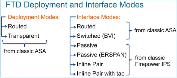
Der FTD-Weiterleitungsmechanismus für die Datenebene hängt vom Schnittstellenmodus ab. Im nächsten Bild werden die verschiedenen Schnittstellenmodi zusammen mit den FTD-Bereitstellungsmodi zusammengefasst:
In der Tabelle ist zusammengefasst, wie die FTD Pakete auf Datenebene abhängig vom Schnittstellenmodus weiterleitet. Die Weiterleitungsmechanismen sind in der Reihenfolge ihrer Präferenz aufgelistet:
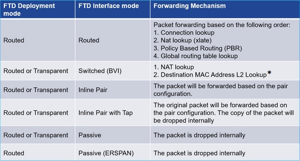
* Ein FTD im transparenten Modus führt in einigen Situationen eine Routensuche durch:
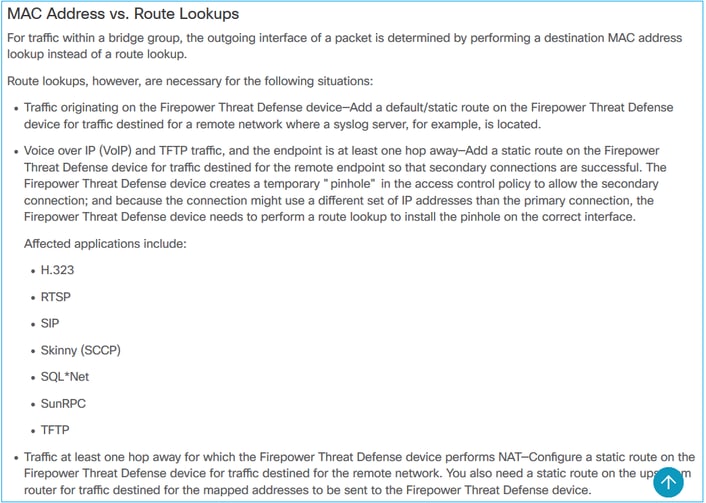
Weitere Informationen finden Sie im FMC-Leitfaden.
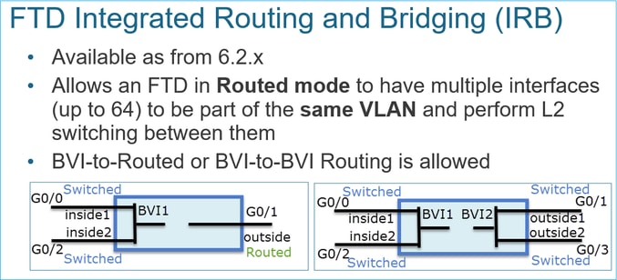
Ab Version 6.2.x unterstützt der FTD Integrated Routing and Bridging (IRB):
BVI-Verifizierungsbefehle:
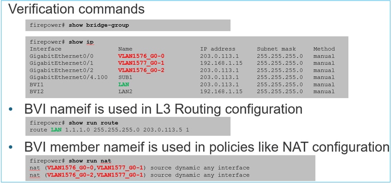
Kernpunkt
Bei gerouteten Schnittstellen oder BVIs (IRB) basiert die Paketweiterleitung auf der folgenden Reihenfolge:
- Verbindungssuche
- NAT-Suche (Ziel-NAT, auch als UN-NAT bezeichnet)
- Richtlinienbasiertes Routing
- Globale Routingtabellen-Suche
Wie sieht es mit der Quell-NAT aus?
Die Quell-NAT wird nach der globalen Routing-Suche überprüft.
Der Schwerpunkt des weiteren Dokuments liegt auf dem Modus der gerouteten Schnittstelle.
LINA-Routingverhalten
Im gerouteten Schnittstellenmodus leitet FTD LINA die Pakete in zwei Phasen weiter:
Phase 1 - Bestimmung der Ausgangsschnittstelle
Phase 2 - Next-Hop-Auswahl
Betrachten Sie diese Topologie:
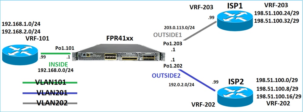
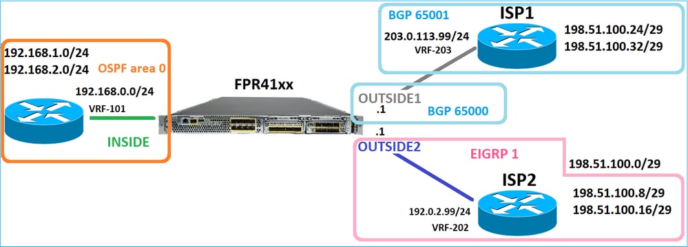
Und dieses Routing-Design:
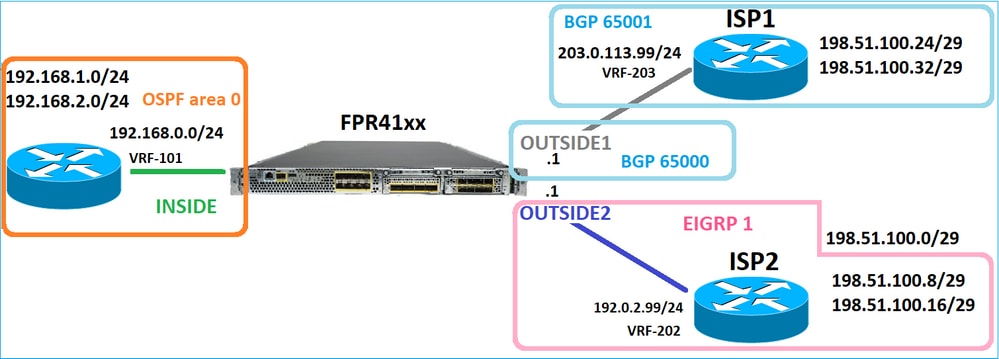
FTD-Routing-Konfiguration:
firepower# show run router
router ospf 1
network 192.168.0.0 255.255.255.0 area 0
log-adj-changes
!
router bgp 65000
bgp log-neighbor-changes
bgp router-id vrf auto-assign
address-family ipv4 unicast
neighbor 203.0.113.99 remote-as 65001
neighbor 203.0.113.99 ebgp-multihop 255
neighbor 203.0.113.99 transport path-mtu-discovery disable
neighbor 203.0.113.99 activate
no auto-summary
no synchronization
exit-address-family
!
router eigrp 1
no default-information in
no default-information out
no eigrp log-neighbor-warnings
no eigrp log-neighbor-changes
network 192.0.2.0 255.255.255.0
!
firepower# show run route
route OUTSIDE2 198.51.100.0 255.255.255.248 192.0.2.99 1
FTD Routing Information Base (RIB) - Kontrollebene:
firepower# show route | begin Gate
Gateway of last resort is not set

C 192.0.2.0 255.255.255.0 is directly connected, OUTSIDE2
L 192.0.2.1 255.255.255.255 is directly connected, OUTSIDE2
C 192.168.0.0 255.255.255.0 is directly connected, INSIDE
L 192.168.0.1 255.255.255.255 is directly connected, INSIDE
O 192.168.1.1 255.255.255.255
[110/11] via 192.168.0.99, 01:11:25, INSIDE
O 192.168.2.1 255.255.255.255
[110/11] via 192.168.0.99, 01:11:15, INSIDE
S 198.51.100.0 255.255.255.248 [1/0] via 192.0.2.99, OUTSIDE2
D 198.51.100.8 255.255.255.248
[90/130816] via 192.0.2.99, 01:08:11, OUTSIDE2
D 198.51.100.16 255.255.255.248
[90/130816] via 192.0.2.99, 01:08:04, OUTSIDE2
B 198.51.100.24 255.255.255.248 [20/0] via 203.0.113.99, 00:28:29
B 198.51.100.32 255.255.255.248 [20/0] via 203.0.113.99, 00:28:16
C 203.0.113.0 255.255.255.0 is directly connected, OUTSIDE1
L 203.0.113.1 255.255.255.255 is directly connected, OUTSIDE1
Die entsprechende FTD Accelerated Security Path (ASP)-Routing-Tabelle - Datenebene:
firepower# show asp table routing
route table timestamp: 91
in 169.254.1.1 255.255.255.255 identity
in 192.168.0.1 255.255.255.255 identity
in 192.0.2.1 255.255.255.255 identity
in 192.168.1.1 255.255.255.255 via 192.168.0.99, INSIDE
in 192.168.2.1 255.255.255.255 via 192.168.0.99, INSIDE
in 203.0.113.1 255.255.255.255 identity
in 169.254.1.0 255.255.255.248 nlp_int_tap
in 198.51.100.0 255.255.255.248 via 192.0.2.99, OUTSIDE2
in 198.51.100.8 255.255.255.248 via 192.0.2.99, OUTSIDE2
in 198.51.100.16 255.255.255.248 via 192.0.2.99, OUTSIDE2
in 198.51.100.24 255.255.255.248 via 203.0.113.99 (unresolved, timestamp: 89)
in 198.51.100.32 255.255.255.248 via 203.0.113.99 (unresolved, timestamp: 90)
in 192.168.0.0 255.255.255.0 INSIDE
in 192.0.2.0 255.255.255.0 OUTSIDE2
in 203.0.113.0 255.255.255.0 OUTSIDE1
in ff02::1 ffff:ffff:ffff:ffff:ffff:ffff:ffff:ffff identity
in ff02::1:ff01:3 ffff:ffff:ffff:ffff:ffff:ffff:ffff:ffff identity
in ff02::1:ff00:1 ffff:ffff:ffff:ffff:ffff:ffff:ffff:ffff identity
in fe80::200:ff:fe01:3 ffff:ffff:ffff:ffff:ffff:ffff:ffff:ffff identity
in fd00:0:0:1::1 ffff:ffff:ffff:ffff:ffff:ffff:ffff:ffff identity
in fd00:0:0:1:: ffff:ffff:ffff:ffff:: nlp_int_tap
out 255.255.255.255 255.255.255.255 OUTSIDE1
out 203.0.113.1 255.255.255.255 OUTSIDE1
out 203.0.113.0 255.255.255.0 OUTSIDE1
out 224.0.0.0 240.0.0.0 OUTSIDE1
out 255.255.255.255 255.255.255.255 OUTSIDE2
out 192.0.2.1 255.255.255.255 OUTSIDE2
out 198.51.100.0 255.255.255.248 via 192.0.2.99, OUTSIDE2
out 198.51.100.8 255.255.255.248 via 192.0.2.99, OUTSIDE2
out 198.51.100.16 255.255.255.248 via 192.0.2.99, OUTSIDE2
out 192.0.2.0 255.255.255.0 OUTSIDE2
out 224.0.0.0 240.0.0.0 OUTSIDE2
out 255.255.255.255 255.255.255.255 INSIDE
out 192.168.0.1 255.255.255.255 INSIDE
out 192.168.1.1 255.255.255.255 via 192.168.0.99, INSIDE
out 192.168.2.1 255.255.255.255 via 192.168.0.99, INSIDE
out 192.168.0.0 255.255.255.0 INSIDE
out 224.0.0.0 240.0.0.0 INSIDE
out 255.255.255.255 255.255.255.255 cmi_mgmt_int_tap
out 224.0.0.0 240.0.0.0 cmi_mgmt_int_tap
out 255.255.255.255 255.255.255.255 ha_ctl_nlp_int_tap
out 224.0.0.0 240.0.0.0 ha_ctl_nlp_int_tap
out 255.255.255.255 255.255.255.255 ccl_ha_nlp_int_tap
out 224.0.0.0 240.0.0.0 ccl_ha_nlp_int_tap
out 255.255.255.255 255.255.255.255 nlp_int_tap
out 169.254.1.1 255.255.255.255 nlp_int_tap
out 169.254.1.0 255.255.255.248 nlp_int_tap
out 224.0.0.0 240.0.0.0 nlp_int_tap
out fd00:0:0:1::1 ffff:ffff:ffff:ffff:ffff:ffff:ffff:ffff nlp_int_tap
out fd00:0:0:1:: ffff:ffff:ffff:ffff:: nlp_int_tap
out fe80:: ffc0:: nlp_int_tap
out ff00:: ff00:: nlp_int_tap
out 0.0.0.0 0.0.0.0 via 0.0.0.0, identity
out :: :: via 0.0.0.0, identity
Wichtigste Punkte
Der FTD (ähnlich wie eine Adaptive Security Appliance - ASA) bestimmt zunächst die Ausgangs- (Egress-) Schnittstelle eines Pakets (dazu werden die "in"-Einträge der ASP-Routing-Tabelle betrachtet). Für die ermittelte Schnittstelle versucht er dann, den nächsten Hop zu finden (dafür schaut er sich die 'out'-Einträge der ASP-Routing-Tabelle an). Beispiele:
firepower# show asp table routing | include in.*198.51.100.0
in 198.51.100.0 255.255.255.248 via 192.0.2.99, OUTSIDE2
firepower#
firepower# show asp table routing | include out.*OUTSIDE2
out 255.255.255.255 255.255.255.255 OUTSIDE2
out 192.0.2.1 255.255.255.255 OUTSIDE2
out 198.51.100.0 255.255.255.248 via 192.0.2.99, OUTSIDE2
out 198.51.100.8 255.255.255.248 via 192.0.2.99, OUTSIDE2
out 198.51.100.16 255.255.255.248 via 192.0.2.99, OUTSIDE2
out 192.0.2.0 255.255.255.0 OUTSIDE2
out 224.0.0.0 240.0.0.0 OUTSIDE2
Schließlich überprüft die LINA für den aufgelösten Next-Hop den ARP-Cache auf eine gültige Adjacency.
Das Paket-Tracer-Tool von FTD bestätigt diesen Prozess:
firepower# packet-tracer input INSIDE icmp 192.168.1.1 8 0 198.51.100.1

Phase: 1
Type: ACCESS-LIST
Subtype:
Result: ALLOW
Elapsed time: 7582 ns
Config:
Implicit Rule
Additional Information:
MAC Access list

Phase: 2
Type: INPUT-ROUTE-LOOKUP
Subtype: Resolve Egress Interface
Result: ALLOW
Elapsed time: 8474 ns
Config:
Additional Information:
Found next-hop 192.0.2.99 using egress ifc OUTSIDE2(vrfid:0)

Phase: 3
Type: ACCESS-LIST
Subtype: log
Result: ALLOW
Elapsed time: 5017 ns
Config:
access-group CSM_FW_ACL_ global
access-list CSM_FW_ACL_ advanced permit ip any any rule-id 268434433
access-list CSM_FW_ACL_ remark rule-id 268434433: ACCESS POLICY: mzafeiro_empty - Default
access-list CSM_FW_ACL_ remark rule-id 268434433: L4 RULE: DEFAULT ACTION RULE
Additional Information:
This packet will be sent to snort for additional processing where a verdict will be reached

Phase: 4
Type: CONN-SETTINGS
Subtype:
Result: ALLOW
Elapsed time: 5017 ns
Config:
class-map class-default
match any
policy-map global_policy
class class-default
set connection advanced-options UM_STATIC_TCP_MAP
service-policy global_policy global
Additional Information:

Phase: 5
Type: NAT
Subtype: per-session
Result: ALLOW
Elapsed time: 5017 ns
Config:
Additional Information:

Phase: 6
Type: IP-OPTIONS
Subtype:
Result: ALLOW
Elapsed time: 5017 ns
Config:
Additional Information:

Phase: 7
Type: INSPECT
Subtype: np-inspect
Result: ALLOW
Elapsed time: 57534 ns
Config:
class-map inspection_default
match default-inspection-traffic
policy-map global_policy
class inspection_default
inspect icmp
service-policy global_policy global
Additional Information:

Phase: 8
Type: INSPECT
Subtype: np-inspect
Result: ALLOW
Elapsed time: 3122 ns
Config:
Additional Information:

Phase: 9
Type: NAT
Subtype: per-session
Result: ALLOW
Elapsed time: 29882 ns
Config:
Additional Information:

Phase: 10
Type: IP-OPTIONS
Subtype:
Result: ALLOW
Elapsed time: 446 ns
Config:
Additional Information:

Phase: 11
Type: FLOW-CREATION
Subtype:
Result: ALLOW
Elapsed time: 20962 ns
Config:
Additional Information:
New flow created with id 178, packet dispatched to next module

Phase: 12
Type: EXTERNAL-INSPECT
Subtype:
Result: ALLOW
Elapsed time: 20070 ns
Config:
Additional Information:
Application: 'SNORT Inspect'

Phase: 13
Type: SNORT
Subtype:
Result: ALLOW
Elapsed time: 870592 ns
Config:
Additional Information:
Snort Trace:
Packet: ICMP
Session: new snort session
Snort id 1, NAP id 1, IPS id 0, Verdict PASS
Snort Verdict: (pass-packet) allow this packet

Phase: 14
Type: INPUT-ROUTE-LOOKUP-FROM-OUTPUT-ROUTE-LOOKUP
Subtype: Resolve Preferred Egress interface
Result: ALLOW
Elapsed time: 6244 ns
Config:
Additional Information:
Found next-hop 192.0.2.99 using egress ifc OUTSIDE2(vrfid:0)

Phase: 15
Type: ADJACENCY-LOOKUP
Subtype: Resolve Nexthop IP address to MAC
Result: ALLOW
Elapsed time: 1784 ns
Config:
Additional Information:
Found adjacency entry for Next-hop 192.0.2.99 on interface OUTSIDE2
Adjacency :Active
MAC address 4c4e.35fc.fcd8 hits 5 reference 1

Result:
input-interface: INSIDE(vrfid:0)
input-status: up
input-line-status: up
output-interface: OUTSIDE2(vrfid:0)
output-status: up
output-line-status: up
Action: allow
Time Taken: 1046760 ns
Die FTD-ARP-Tabelle, wie sie in der Kontrollebene angezeigt wird:
firepower# show arp
OUTSIDE1 203.0.113.99 4c4e.35fc.fcd8 3051
OUTSIDE2 192.0.2.99 4c4e.35fc.fcd8 5171
So erzwingen Sie die ARP-Auflösung:
firepower# ping 192.168.0.99
Type escape sequence to abort.
Sending 5, 100-byte ICMP Echos to 192.168.0.99, timeout is 2 seconds:
!!!!!
Success rate is 100 percent (5/5), round-trip min/avg/max = 1/1/1 ms
firepower# show arp
INSIDE 192.168.0.99 4c4e.35fc.fcd8 45
OUTSIDE1 203.0.113.99 4c4e.35fc.fcd8 32
OUTSIDE2 192.0.2.99 4c4e.35fc.fcd8 1
Die FTD-ARP-Tabelle aus der Datenebene:
firepower# show asp table arp

Context: single_vf, Interface: OUTSIDE1
203.0.113.99 Active 4c4e.35fc.fcd8 hits 2 reference 1

Context: single_vf, Interface: OUTSIDE2
192.0.2.99 Active 4c4e.35fc.fcd8 hits 5 reference 0

Context: single_vf, Interface: INSIDE
192.168.0.99 Active 4c4e.35fc.fcd8 hits 5 reference 0

Context: single_vf, Interface: identity
:: Active 0000.0000.0000 hits 0 reference 0
0.0.0.0 Active 0000.0000.0000 hits 848 reference 0

Last clearing of hits counters: Never
FTD-Arbeitsauftrag
Das Bild zeigt die Reihenfolge der Vorgänge und den Ort, an dem die ASP-Routing-Prüfungen für die Ein- und Ausgabe durchgeführt werden:

Konfigurieren
Fall 1: Weiterleitung auf Basis der Verbindungssuche
Wie bereits erwähnt, ist die Hauptkomponente der FTD LINA Engine der Datapath-Prozess (mehrere Instanzen, basierend auf der Anzahl der Device-Cores). Darüber hinaus besteht der Datenpfad (auch als Accelerated Security Path - ASP bezeichnet) aus 2 Pfaden:
- Langsamer Pfad = Verantwortlich für den Aufbau der neuen Verbindung (wird im Fast Path eingetragen).
- Fast Path: Verarbeitet Pakete, die zu etablierten Verbindungen gehören.
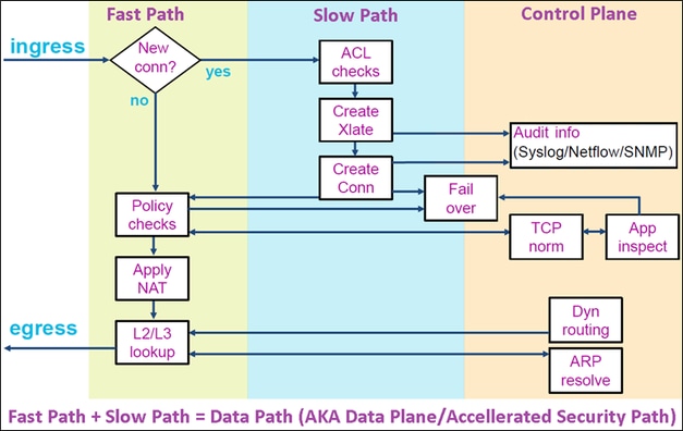
- Befehle wie show route und show arp zeigen den Inhalt der Kontrollebene an.
- Auf der anderen Seite zeigen Befehle wie show asp table routing und show asp table arp den Inhalt von ASP (Datapath) an, der tatsächlich angewendet wird.
Aktivieren Sie die Erfassung mit Trace auf der FTD INSIDE-Schnittstelle:
firepower# capture CAPI trace detail interface INSIDE match ip host 192.168.1.1 host 198.51.100.1
Öffnen Sie eine Telnet-Sitzung über die FTD:
Router1# telnet 198.51.100.1 /vrf VRF-101 /source-interface lo1
Trying 198.51.100.1 ... Open
Die FTD-Aufnahmen zeigen die Pakete vom Beginn der Verbindung an (TCP 3-Wege-Handshake wird erfasst):
firepower# show capture CAPI

26 packets captured

1: 10:50:38.407190 802.1Q vlan#101 P0 192.168.1.1.57734 > 198.51.100.1.23: S 1306692135:1306692135(0) win 4128 <mss 536>
2: 10:50:38.408929 802.1Q vlan#101 P0 198.51.100.1.23 > 192.168.1.1.57734: S 1412677784:1412677784(0) ack 1306692136 win 4128 <mss 536>
3: 10:50:38.409265 802.1Q vlan#101 P0 192.168.1.1.57734 > 198.51.100.1.23: . ack 1412677785 win 4128
4: 10:50:38.409433 802.1Q vlan#101 P0 192.168.1.1.57734 > 198.51.100.1.23: P 1306692136:1306692154(18) ack 1412677785 win 4128
5: 10:50:38.409845 802.1Q vlan#101 P0 192.168.1.1.57734 > 198.51.100.1.23: . ack 1412677785 win 4128
6: 10:50:38.410135 802.1Q vlan#101 P0 198.51.100.1.23 > 192.168.1.1.57734: . ack 1306692154 win 4110
7: 10:50:38.411355 802.1Q vlan#101 P0 198.51.100.1.23 > 192.168.1.1.57734: P 1412677785:1412677797(12) ack 1306692154 win 4110
8: 10:50:38.413049 802.1Q vlan#101 P0 192.168.1.1.57734 > 198.51.100.1.23: P 1306692154:1306692157(3) ack 1412677797 win 4116
9: 10:50:38.413140 802.1Q vlan#101 P0 192.168.1.1.57734 > 198.51.100.1.23: P 1306692157:1306692166(9) ack 1412677797 win 4116
10: 10:50:38.414071 802.1Q vlan#101 P0 198.51.100.1.23 > 192.168.1.1.57734: . 1412677797:1412678322(525) ack 1306692154 win 4110
...
Verfolgen Sie das erste Paket (TCP SYN). Dieses Paket durchläuft den FTD LINA Slow Path. In diesem Fall wird eine globale Routing-Suche durchgeführt:
firepower# show capture CAPI packet-number 1 trace

26 packets captured

   1: 10:50:38.407190 802.1Q vlan#101 P0 192.168.1.1.57734 > 198.51.100.1.23: S 1306692135:1306692135(0) win 4128 <mss 536>
Phase: 1
Type: CAPTURE
Subtype:
Result: ALLOW
Elapsed time: 4683 ns
Config:
Additional Information:
Forward Flow based lookup yields rule:
in id=0x1505f1d17940, priority=13, domain=capture, deny=false
hits=1783, user_data=0x1505f2096910, cs_id=0x0, l3_type=0x0
src mac=0000.0000.0000, mask=0000.0000.0000
dst mac=0000.0000.0000, mask=0000.0000.0000
input_ifc=INSIDE, output_ifc=any

Phase: 2
Type: ACCESS-LIST
Subtype:
Result: ALLOW
Elapsed time: 4683 ns
Config:
Implicit Rule
Additional Information:
Forward Flow based lookup yields rule:
in id=0x1502a7ba4d40, priority=1, domain=permit, deny=false
hits=28, user_data=0x0, cs_id=0x0, l3_type=0x8
src mac=0000.0000.0000, mask=0000.0000.0000
dst mac=0000.0000.0000, mask=0100.0000.0000
input_ifc=INSIDE, output_ifc=any

Phase: 3
Type: INPUT-ROUTE-LOOKUP
Subtype: Resolve Egress Interface
Result: ALLOW
Elapsed time: 5798 ns
Config:
Additional Information:
Found next-hop 192.0.2.99 using egress ifc OUTSIDE2(vrfid:0)

Phase: 4
Type: ACCESS-LIST
Subtype: log
Result: ALLOW
Elapsed time: 3010 ns
Config:
access-group CSM_FW_ACL_ global
access-list CSM_FW_ACL_ advanced permit ip any any rule-id 268434433
access-list CSM_FW_ACL_ remark rule-id 268434433: ACCESS POLICY: mzafeiro_empty - Default
access-list CSM_FW_ACL_ remark rule-id 268434433: L4 RULE: DEFAULT ACTION RULE
Additional Information:
This packet will be sent to snort for additional processing where a verdict will be reached
Forward Flow based lookup yields rule:
in id=0x1505f1e2e980, priority=12, domain=permit, deny=false
hits=4, user_data=0x15024a56b940, cs_id=0x0, use_real_addr, flags=0x0, protocol=0
src ip/id=0.0.0.0, mask=0.0.0.0, port=0, tag=any, ifc=any
dst ip/id=0.0.0.0, mask=0.0.0.0, port=0, tag=any, ifc=any,, dscp=0x0, nsg_id=none
input_ifc=any, output_ifc=any

Phase: 5
Type: CONN-SETTINGS
Subtype:
Result: ALLOW
Elapsed time: 3010 ns
Config:
class-map class-default
match any
policy-map global_policy
class class-default
set connection advanced-options UM_STATIC_TCP_MAP
service-policy global_policy global
Additional Information:
Forward Flow based lookup yields rule:
in id=0x1505f1f18bc0, priority=7, domain=conn-set, deny=false
hits=4, user_data=0x1505f1f13f70, cs_id=0x0, use_real_addr, flags=0x0, protocol=0
src ip/id=0.0.0.0, mask=0.0.0.0, port=0, tag=any
dst ip/id=0.0.0.0, mask=0.0.0.0, port=0, tag=any, dscp=0x0, nsg_id=none
input_ifc=INSIDE(vrfid:0), output_ifc=any

Phase: 6
Type: NAT
Subtype: per-session
Result: ALLOW
Elapsed time: 3010 ns
Config:
Additional Information:
Forward Flow based lookup yields rule:
in id=0x15052e96b150, priority=0, domain=nat-per-session, deny=false
hits=125, user_data=0x0, cs_id=0x0, reverse, use_real_addr, flags=0x0, protocol=6
src ip/id=0.0.0.0, mask=0.0.0.0, port=0, tag=any
dst ip/id=0.0.0.0, mask=0.0.0.0, port=0, tag=any, dscp=0x0, nsg_id=none
input_ifc=any, output_ifc=any

Phase: 7
Type: IP-OPTIONS
Subtype:
Result: ALLOW
Elapsed time: 3010 ns
Config:
Additional Information:
Forward Flow based lookup yields rule:
in id=0x1502a7bacde0, priority=0, domain=inspect-ip-options, deny=true
hits=19, user_data=0x0, cs_id=0x0, reverse, flags=0x0, protocol=0
src ip/id=0.0.0.0, mask=0.0.0.0, port=0, tag=any
dst ip/id=0.0.0.0, mask=0.0.0.0, port=0, tag=any, dscp=0x0, nsg_id=none
input_ifc=INSIDE(vrfid:0), output_ifc=any

Phase: 8
Type: NAT
Subtype: per-session
Result: ALLOW
Elapsed time: 52182 ns
Config:
Additional Information:
Reverse Flow based lookup yields rule:
in id=0x15052e96b150, priority=0, domain=nat-per-session, deny=false
hits=127, user_data=0x0, cs_id=0x0, reverse, use_real_addr, flags=0x0, protocol=6
src ip/id=0.0.0.0, mask=0.0.0.0, port=0, tag=any
dst ip/id=0.0.0.0, mask=0.0.0.0, port=0, tag=any, dscp=0x0, nsg_id=none
input_ifc=any, output_ifc=any

Phase: 9
Type: IP-OPTIONS
Subtype:
Result: ALLOW
Elapsed time: 892 ns
Config:
Additional Information:
Reverse Flow based lookup yields rule:
in id=0x1502a7f9b460, priority=0, domain=inspect-ip-options, deny=true
hits=38, user_data=0x0, cs_id=0x0, reverse, flags=0x0, protocol=0
src ip/id=0.0.0.0, mask=0.0.0.0, port=0, tag=any
dst ip/id=0.0.0.0, mask=0.0.0.0, port=0, tag=any, dscp=0x0, nsg_id=none
input_ifc=OUTSIDE2(vrfid:0), output_ifc=any

Phase: 10
Type: FLOW-CREATION
Subtype:
Result: ALLOW
Elapsed time: 25422 ns
Config:
Additional Information:
New flow created with id 244, packet dispatched to next module
Module information for forward flow ...
snp_fp_inspect_ip_options
snp_fp_tcp_normalizer
snp_fp_tcp_proxy
snp_fp_snort
snp_fp_tcp_proxy
snp_fp_translate
snp_fp_tcp_normalizer
snp_fp_adjacency
snp_fp_fragment
snp_ifc_stat

Module information for reverse flow ...
snp_fp_inspect_ip_options
snp_fp_tcp_normalizer
snp_fp_translate
snp_fp_tcp_proxy
snp_fp_snort
snp_fp_tcp_proxy
snp_fp_tcp_normalizer
snp_fp_adjacency
snp_fp_fragment
snp_ifc_stat

Phase: 11
Type: EXTERNAL-INSPECT
Subtype:
Result: ALLOW
Elapsed time: 36126 ns
Config:
Additional Information:
Application: 'SNORT Inspect'

Phase: 12
Type: SNORT
Subtype:
Result: ALLOW
Elapsed time: 564636 ns
Config:
Additional Information:
Snort Trace:
Packet: TCP, SYN, seq 182318660
Session: new snort session
AppID: service unknown (0), application unknown (0)
Snort id 28, NAP id 1, IPS id 0, Verdict PASS
Snort Verdict: (pass-packet) allow this packet

Phase: 13
Type: INPUT-ROUTE-LOOKUP-FROM-OUTPUT-ROUTE-LOOKUP
Subtype: Resolve Preferred Egress interface
Result: ALLOW
Elapsed time: 7136 ns
Config:
Additional Information:
Found next-hop 192.0.2.99 using egress ifc OUTSIDE2(vrfid:0)

Phase: 14
Type: ADJACENCY-LOOKUP
Subtype: Resolve Nexthop IP address to MAC
Result: ALLOW
Elapsed time: 2230 ns
Config:
Additional Information:
Found adjacency entry for Next-hop 192.0.2.99 on interface OUTSIDE2
Adjacency :Active
MAC address 4c4e.35fc.fcd8 hits 10 reference 1

Phase: 15
Type: CAPTURE
Subtype:
Result: ALLOW
Elapsed time: 5352 ns
Config:
Additional Information:
Forward Flow based lookup yields rule:
out id=0x150521389870, priority=13, domain=capture, deny=false
hits=1788, user_data=0x1505f1d2b630, cs_id=0x0, l3_type=0x0
src mac=0000.0000.0000, mask=0000.0000.0000
dst mac=0000.0000.0000, mask=0000.0000.0000
input_ifc=OUTSIDE2, output_ifc=any

Result:
input-interface: INSIDE(vrfid:0)
input-status: up
input-line-status: up
output-interface: OUTSIDE2(vrfid:0)
output-status: up
output-line-status: up
Action: allow
Time Taken: 721180 ns

1 packet shown
firepower#
Verfolgen Sie ein weiteres Eingangspaket aus demselben Datenfluss. Das Paket, das einer aktiven Verbindung entspricht:
firepower# show capture CAPI packet-number 3 trace

33 packets captured

3: 10:50:38.409265 802.1Q vlan#101 P0 192.168.1.1.57734 > 198.51.100.1.23: . ack 1412677785 win 4128
Phase: 1
Type: CAPTURE
Subtype:
Result: ALLOW
Elapsed time: 2676 ns
Config:
Additional Information:
Forward Flow based lookup yields rule:
in id=0x1505f1d17940, priority=13, domain=capture, deny=false
hits=105083, user_data=0x1505f2096910, cs_id=0x0, l3_type=0x0
src mac=0000.0000.0000, mask=0000.0000.0000
dst mac=0000.0000.0000, mask=0000.0000.0000
input_ifc=INSIDE, output_ifc=any

Phase: 2
Type: ACCESS-LIST
Subtype:
Result: ALLOW
Elapsed time: 2676 ns
Config:
Implicit Rule
Additional Information:
Forward Flow based lookup yields rule:
in id=0x1502a7ba4d40, priority=1, domain=permit, deny=false
hits=45, user_data=0x0, cs_id=0x0, l3_type=0x8
src mac=0000.0000.0000, mask=0000.0000.0000
dst mac=0000.0000.0000, mask=0100.0000.0000
input_ifc=INSIDE, output_ifc=any

Phase: 3
Type: FLOW-LOOKUP
Subtype:
Result: ALLOW
Elapsed time: 1338 ns
Config:
Additional Information:
Found flow with id 2552, using existing flow
Module information for forward flow ...
snp_fp_inspect_ip_options
snp_fp_tcp_normalizer
snp_fp_snort
snp_fp_translate
snp_fp_tcp_normalizer
snp_fp_adjacency
snp_fp_fragment
snp_ifc_stat

Module information for reverse flow ...
snp_fp_inspect_ip_options
snp_fp_tcp_normalizer
snp_fp_translate
snp_fp_snort
snp_fp_tcp_normalizer
snp_fp_adjacency
snp_fp_fragment
snp_ifc_stat

Phase: 4
Type: EXTERNAL-INSPECT
Subtype:
Result: ALLOW
Elapsed time: 16502 ns
Config:
Additional Information:
Application: 'SNORT Inspect'

Phase: 5
Type: SNORT
Subtype:
Result: ALLOW
Elapsed time: 12934 ns
Config:
Additional Information:
Snort Trace:
Packet: TCP, ACK, seq 1306692136, ack 1412677785
AppID: service unknown (0), application unknown (0)
Snort id 19, NAP id 1, IPS id 0, Verdict PASS
Snort Verdict: (pass-packet) allow this packet

Result:
input-interface: INSIDE(vrfid:0)
input-status: up
input-line-status: up
Action: allow
Time Taken: 36126 ns

1 packet shown
firepower#
Unverankertes Timeout
Das Problem
Eine vorübergehende Routen-Instabilität kann dazu führen, dass langlebige (Elefanten-) UDP-Verbindungen über den FTD über andere FTD-Schnittstellen als gewünscht hergestellt werden.
Die Lösung
Um dieses Problem zu beheben, setzen Sie timeout floating-conn auf einen anderen Wert als den Standardwert, der deaktiviert ist:
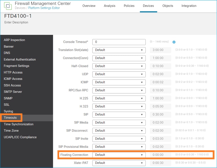
In der Befehlsreferenz:

Weitere Informationen finden Sie in der Fallstudie: UDP-Verbindungen schlagen nach dem erneuten Laden von der CiscoLive BRKSEC-3020-Sitzung fehl:
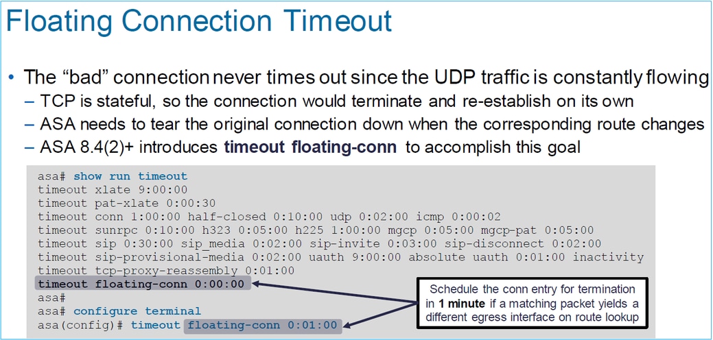
Timeout bei Verbindungs-Holddown
Das Problem
Eine Route fällt aus (wird entfernt), aber der Datenverkehr entspricht einer bestehenden Verbindung.
Die Lösung
Die Funktion zum Zurückhalten von Zeitüberschreitungen wurde in ASA 9.6.2 hinzugefügt. Die Funktion ist standardmäßig aktiviert, wird aber derzeit (7.1.x) nicht von der FMC-Benutzeroberfläche oder FlexConfig unterstützt. Zugehörige Verbesserung: ENH: Timeout-Verbindung-Holddown nicht verfügbar für Konfiguration in FMC
Aus dem ASA CLI-Leitfaden:

firepower# show run all timeout
timeout xlate 3:00:00
timeout pat-xlate 0:00:30
timeout conn 1:00:00 half-closed 0:10:00 udp 0:02:00 sctp 0:02:00 icmp 0:00:02
timeout sunrpc 0:10:00 h323 0:05:00 h225 1:00:00 mgcp 0:05:00 mgcp-pat 0:05:00
timeout sip 0:30:00 sip_media 0:02:00 sip-invite 0:03:00 sip-disconnect 0:02:00
timeout sip-provisional-media 0:02:00 uauth 0:05:00 absolute
timeout tcp-proxy-reassembly 0:00:30
timeout floating-conn 0:00:00
timeout conn-holddown 0:00:15
timeout igp stale-route 0:01:10
Fall 2: Weiterleitung auf Basis der NAT-Suche
Anforderung
Konfigurieren Sie diese NAT-Regel:
- Typ: Statisch
- Quellschnittstelle: INSIDE
- Zielschnittstelle: OUTSIDE1
- Quelle: 192.168.1.1
- Ursprünglicher Zielort: 198.51.100.1
- Übersetzte Quelle: 192.168.1.1
- Übersetztes Ziel: 198.51.100.1
Lösung

Die bereitgestellte NAT-Regel in der FTD-CLI:
firepower# show run nat
nat (INSIDE,OUTSIDE1) source static host_192.168.1.1 host_192.168.1.1 destination static host_198.51.100.1 host_198.51.100.1
firepower# show nat
Manual NAT Policies (Section 1)
1 (INSIDE) to (OUTSIDE1) source static host_192.168.1.1 host_192.168.1.1 destination static host_198.51.100.1 host_198.51.100.1
translate_hits = 0, untranslate_hits = 0
Konfigurieren Sie 3 Aufnahmen:
firepower# capture CAPI trace detail interface INSIDE match ip host 192.168.1.1 host 198.51.100.1
firepower# capture CAPO1 interface OUTSIDE1 match ip host 192.168.1.1 any
firepower# capture CAPO2 interface OUTSIDE2 match ip host 192.168.1.1 any
firepower# show capture
capture CAPI type raw-data trace detail interface INSIDE [Capturing - 0 bytes]
match ip host 192.168.1.1 host 198.51.100.1
capture CAPO1 type raw-data interface OUTSIDE1 [Capturing - 0 bytes]
match ip host 192.168.1.1 any
capture CAPO2 type raw-data interface OUTSIDE2 [Capturing - 0 bytes]
match ip host 192.168.1.1 any
Starten Sie eine Telnet-Sitzung von 192.168.1.1 bis 198.51.100.1:
Router1# telnet 198.51.100.1 /vrf VRF-101 /source-interface lo1
Trying 198.51.100.1 ...
% Connection timed out; remote host not responding
Pakete kommen über FTD an, aber nichts verlässt die Schnittstellen OUTSIDE1 oder OUTSIDE2:
firepower# show capture
capture CAPI type raw-data trace detail interface INSIDE [Capturing - 156 bytes]
match ip host 192.168.1.1 host 198.51.100.1
capture CAPO1 type raw-data interface OUTSIDE1 [Capturing - 0 bytes]
match ip host 192.168.1.1 any
capture CAPO2 type raw-data interface OUTSIDE2 [Capturing - 0 bytes]
match ip host 192.168.1.1 any
Verfolgen Sie das TCP-SYN-Paket. Phase 3 (UN-NAT) zeigt, dass NAT (speziell UN-NAT) das Paket für die Next-Hop-Suche an die OUTSIDE1-Schnittstelle umgeleitet hat:
firepower# show capture CAPI
2 packets captured
1: 11:22:59.179678 802.1Q vlan#101 P0 192.168.1.1.38790 > 198.51.100.1.23: S 1174675193:1174675193(0) win 4128 <mss 536>
2: 11:23:01.179632 802.1Q vlan#101 P0 192.168.1.1.38790 > 198.51.100.1.23: S 1174675193:1174675193(0) win 4128 <mss 536>
2 packets shown
firepower#
firepower# show capture CAPI packet-number 1 trace detail

2 packets captured

1: 11:22:59.179678 4c4e.35fc.fcd8 00be.75f6.1dae 0x8100 Length: 62
802.1Q vlan#101 P0 192.168.1.1.38790 > 198.51.100.1.23: S [tcp sum ok] 1174675193:1174675193(0) win 4128 <mss 536> [tos 0xc0] (ttl 255, id 60126)
...

Phase: 3
Type: UN-NAT
Subtype: static
Result: ALLOW
Elapsed time: 6244 ns
Config:
nat (INSIDE,OUTSIDE1) source static host_192.168.1.1 host_192.168.1.1 destination static host_198.51.100.1 host_198.51.100.1
Additional Information:
NAT divert to egress interface OUTSIDE1(vrfid:0)
Untranslate 198.51.100.1/23 to 198.51.100.1/23

...
Phase: 12
Type: FLOW-CREATION
Subtype:
Result: ALLOW
Elapsed time: 25422 ns
Config:
Additional Information:
New flow created with id 2614, packet dispatched to next module
Module information for forward flow ...
snp_fp_inspect_ip_options
snp_fp_tcp_normalizer
snp_fp_tcp_proxy
snp_fp_snort
snp_fp_tcp_proxy
snp_fp_translate
snp_fp_tcp_normalizer
snp_fp_adjacency
snp_fp_fragment
snp_ifc_stat


Phase: 15
Type: INPUT-ROUTE-LOOKUP-FROM-OUTPUT-ROUTE-LOOKUP
Subtype: Resolve Preferred Egress interface
Result: ALLOW
Elapsed time: 8028 ns
Config:
Additional Information:
Found next-hop 192.0.2.99 using egress ifc OUTSIDE2(vrfid:0)

Phase: 16
Type: SUBOPTIMAL-LOOKUP
Subtype: suboptimal next-hop
Result: ALLOW
Elapsed time: 446 ns
Config:
Additional Information:
Input route lookup returned ifc OUTSIDE2 is not same as existing ifc OUTSIDE1

Result:
input-interface: INSIDE(vrfid:0)
input-status: up
input-line-status: up
output-interface: OUTSIDE1(vrfid:0)
output-status: up
output-line-status: up
Action: drop
Time Taken: 777375 ns
Drop-reason: (no-adjacency) No valid adjacency, Drop-location: frame 0x00005577204a7287 flow (NA)/NA


1 packet shown
In diesem Fall bedeutet SUBOPTIMAL-LOOKUP, dass sich die vom NAT-Prozess (OUTSIDE1) festgelegte Ausgangsschnittstelle von der in der ASP-Eingabetabelle angegebenen Ausgangsschnittstelle unterscheidet:
firepower# show asp table routing | include 198.51.100.0
in 198.51.100.0 255.255.255.248 via 192.0.2.99, OUTSIDE2
out 198.51.100.0 255.255.255.248 via 192.0.2.99, OUTSIDE2
Eine mögliche Problemumgehung besteht darin, eine variable statische Route an der OUTSIDE1-Schnittstelle hinzuzufügen:
firepower# show run route
route OUTSIDE2 198.51.100.0 255.255.255.248 192.0.2.99 1
route OUTSIDE1 198.51.100.0 255.255.255.248 203.0.113.99 200
Hinweis: Wenn Sie versuchen, eine statische Route mit derselben Metrik wie die bereits vorhandene hinzuzufügen, wird dieser Fehler angezeigt:
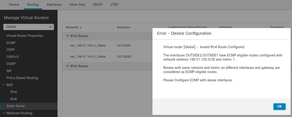
Hinweis: Floating-Routen mit der Entfernungsmetrik 255 sind in der Routing-Tabelle nicht installiert.
Versuchen Sie zu telnet, dass Pakete über die FTD gesendet werden:
Router1# telnet 198.51.100.1 /vrf VRF-101 /source-interface lo1
Trying 198.51.100.1 ...
% Connection timed out; remote host not responding
firepower# show capture
capture CAPI type raw-data trace detail interface INSIDE [Capturing - 156 bytes]
match ip host 192.168.1.1 host 198.51.100.1
capture CAPO1 type raw-data interface OUTSIDE1 [Capturing - 312 bytes]
match ip host 192.168.1.1 any
capture CAPO2 type raw-data interface OUTSIDE2 [Capturing - 386 bytes]
match ip host 192.168.1.1 any
Die Paketverfolgung zeigt, dass die Pakete aufgrund der NAT-Suche an eine ISP1-Schnittstelle (OUTSIDE1) anstelle von ISP2 weitergeleitet werden:
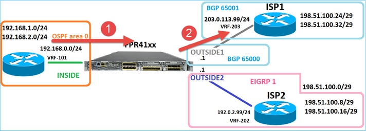
firepower# show capture CAPI packet-number 1 trace

2 packets captured

1: 09:03:02.773962 802.1Q vlan#101 P0 192.168.1.1.16774 > 198.51.100.1.23: S 2910053251:2910053251(0) win 4128 <mss 536>
...

Phase: 3
Type: UN-NAT
Subtype: static
Result: ALLOW
Elapsed time: 4460 ns
Config:
nat (INSIDE,OUTSIDE1) source static host_192.168.1.1 host_192.168.1.1 destination static host_198.51.100.1 host_198.51.100.1
Additional Information:
NAT divert to egress interface OUTSIDE1(vrfid:0)
Untranslate 198.51.100.1/23 to 198.51.100.1/23

...

Phase: 12
Type: FLOW-CREATION
Subtype:
Result: ALLOW
Elapsed time: 29436 ns
Config:
Additional Information:
New flow created with id 2658, packet dispatched to next module
Module information for forward flow ...
snp_fp_inspect_ip_options
snp_fp_tcp_normalizer
snp_fp_snort
snp_fp_translate
snp_fp_tcp_normalizer
snp_fp_adjacency
snp_fp_fragment
snp_ifc_stat

Phase: 15
Type: INPUT-ROUTE-LOOKUP-FROM-OUTPUT-ROUTE-LOOKUP
Subtype: Resolve Preferred Egress interface
Result: ALLOW
Elapsed time: 5798 ns
Config:
Additional Information:
Found next-hop 192.0.2.99 using egress ifc OUTSIDE2(vrfid:0)

Phase: 16
Type: SUBOPTIMAL-LOOKUP
Subtype: suboptimal next-hop
Result: ALLOW
Elapsed time: 446 ns
Config:
Additional Information:
Input route lookup returned ifc OUTSIDE2 is not same as existing ifc OUTSIDE1

Phase: 17
Type: NEXTHOP-LOOKUP-FROM-OUTPUT-ROUTE-LOOKUP
Subtype: Lookup Nexthop on interface
Result: ALLOW
Elapsed time: 1784 ns
Config:
Additional Information:
Found next-hop 203.0.113.99 using egress ifc OUTSIDE1(vrfid:0)

Phase: 18
Type: ADJACENCY-LOOKUP
Subtype: Resolve Nexthop IP address to MAC
Result: ALLOW
Elapsed time: 1338 ns
Config:
Additional Information:
Found adjacency entry for Next-hop 203.0.113.99 on interface OUTSIDE1
Adjacency :Active
MAC address 4c4e.35fc.fcd8 hits 106 reference 2
...

Result:
input-interface: INSIDE(vrfid:0)
input-status: up
input-line-status: up
output-interface: OUTSIDE1(vrfid:0)
output-status: up
output-line-status: up
Action: allow
Time Taken: 723409 ns


1 packet shown
firepower#
Interessanterweise werden in diesem Fall Pakete auf INSIDE und an beiden Ausgangsschnittstellen angezeigt:
firepower# show capture CAPI

2 packets captured

1: 09:03:02.773962 802.1Q vlan#101 P0 192.168.1.1.32134 > 198.51.100.1.23: S 3031010184:3031010184(0) win 4128 <mss 536>
2: 09:03:05.176565 802.1Q vlan#101 P0 192.168.1.1.32134 > 198.51.100.1.23: S 3031010184:3031010184(0) win 4128 <mss 536>
2 packets shown
firepower# show capture CAPO1

4 packets captured

1: 09:03:02.774358 802.1Q vlan#203 P0 192.168.1.1.32134 > 198.51.100.1.23: S 3249840142:3249840142(0) win 4128 <mss 536>
2: 09:03:02.774557 802.1Q vlan#203 P0 192.168.1.1.32134 > 198.51.100.1.23: S 3249840142:3249840142(0) win 4128 <mss 536>
3: 09:03:05.176702 802.1Q vlan#203 P0 192.168.1.1.32134 > 198.51.100.1.23: S 3249840142:3249840142(0) win 4128 <mss 536>
4: 09:03:05.176870 802.1Q vlan#203 P0 192.168.1.1.32134 > 198.51.100.1.23: S 3249840142:3249840142(0) win 4128 <mss 536>
4 packets shown
firepower# show capture CAPO2

5 packets captured

1: 09:03:02.774679 802.1Q vlan#202 P0 192.168.1.1.32134 > 198.51.100.1.23: S 194652172:194652172(0) win 4128 <mss 536>
2: 09:03:02.775457 802.1Q vlan#202 P0 198.51.100.1.23 > 192.168.1.1.32134: S 4075003210:4075003210(0) ack 194652173 win 4128 <mss 536>
3: 09:03:05.176931 802.1Q vlan#202 P0 192.168.1.1.32134 > 198.51.100.1.23: S 194652172:194652172(0) win 4128 <mss 536>
4: 09:03:05.177282 802.1Q vlan#202 P0 198.51.100.1.23 > 192.168.1.1.32134: . ack 194652173 win 4128
5: 09:03:05.180517 802.1Q vlan#202 P0 198.51.100.1.23 > 192.168.1.1.32134: S 4075003210:4075003210(0) ack 194652173 win 4128 <mss 536>
Die Paketdetails enthalten die MAC-Adressinformationen, und eine Nachverfolgung der Pakete an den Schnittstellen OUTSIDE1 und OUTSIDE2 zeigt den Pfad der Pakete an:
firepower# show capture CAPO1 detail

4 packets captured

1: 09:03:02.774358 00be.75f6.1dae 4c4e.35fc.fcd8 0x8100 Length: 62
802.1Q vlan#203 P0 192.168.1.1.32134 > 198.51.100.1.23: S [tcp sum ok] 3249840142:3249840142(0) win 4128 <mss 536> [tos 0xc0] (ttl 255, id 14509)
2: 09:03:02.774557 4c4e.35fc.fcd8 00be.75f6.1dae 0x8100 Length: 62
802.1Q vlan#203 P0 192.168.1.1.32134 > 198.51.100.1.23: S [tcp sum ok] 3249840142:3249840142(0) win 4128 <mss 536> [tos 0xc0] (ttl 254, id 14509)
3: 09:03:05.176702 00be.75f6.1dae 4c4e.35fc.fcd8 0x8100 Length: 62
802.1Q vlan#203 P0 192.168.1.1.32134 > 198.51.100.1.23: S [tcp sum ok] 3249840142:3249840142(0) win 4128 <mss 536> [tos 0xc0] (ttl 255, id 14509)
4: 09:03:05.176870 4c4e.35fc.fcd8 00be.75f6.1dae 0x8100 Length: 62
802.1Q vlan#203 P0 192.168.1.1.32134 > 198.51.100.1.23: S [tcp sum ok] 3249840142:3249840142(0) win 4128 <mss 536> [tos 0xc0] (ttl 254, id 14509)
4 packets shown
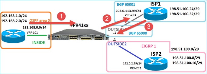
Die Ablaufverfolgung des zurückgegebenen Pakets zeigt eine Umleitung an die OUTSIDE2-Schnittstelle aufgrund der globalen Routingtabellensuche an:
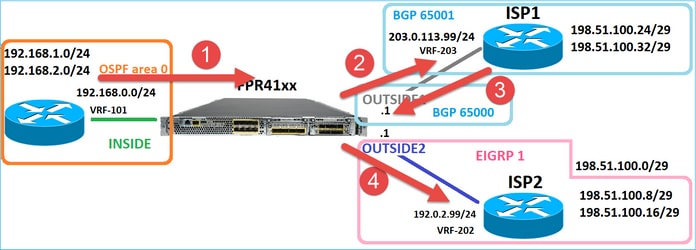
firepower# show capture CAPO1 packet-number 2 trace

4 packets captured

2: 09:03:02.774557 802.1Q vlan#203 P0 192.168.1.1.32134 > 198.51.100.1.23: S 3249840142:3249840142(0) win 4128 <mss 536>
...

Phase: 3
Type: INPUT-ROUTE-LOOKUP
Subtype: Resolve Egress Interface
Result: ALLOW
Elapsed time: 7136 ns
Config:
Additional Information:
Found next-hop 192.0.2.99 using egress ifc OUTSIDE2(vrfid:0)

...

Phase: 10
Type: FLOW-CREATION
Subtype:
Result: ALLOW
Elapsed time: 12488 ns
Config:
Additional Information:
New flow created with id 13156, packet dispatched to next module

...

Phase: 13
Type: INPUT-ROUTE-LOOKUP-FROM-OUTPUT-ROUTE-LOOKUP
Subtype: Resolve Preferred Egress interface
Result: ALLOW
Elapsed time: 3568 ns
Config:
Additional Information:
Found next-hop 192.0.2.99 using egress ifc OUTSIDE2(vrfid:0)

Phase: 14
Type: ADJACENCY-LOOKUP
Subtype: Resolve Nexthop IP address to MAC
Result: ALLOW
Elapsed time: 1338 ns
Config:
Additional Information:
Found adjacency entry for Next-hop 192.0.2.99 on interface OUTSIDE2
Adjacency :Active
MAC address 4c4e.35fc.fcd8 hits 0 reference 1

...

Result:
input-interface: OUTSIDE1(vrfid:0)
input-status: up
input-line-status: up
output-interface: OUTSIDE2(vrfid:0)
output-status: up
output-line-status: up
Action: allow
Time Taken: 111946 ns


1 packet shown
firepower#
Der ISP2-Router sendet die Antwort (SYN/ACK), aber dieses Paket wird an ISP1 umgeleitet, da es mit der bestehenden Verbindung übereinstimmt. Das Paket wird vom FTD verworfen, da keine L2-Adjacency in der ASP-Out-Tabelle vorhanden ist:
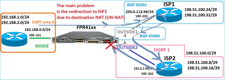
firepower# show capture CAPO2 packet-number 2 trace

5 packets captured

2: 09:03:02.775457 802.1Q vlan#202 P0 198.51.100.1.23 > 192.168.1.1.32134: S 4075003210:4075003210(0) ack 194652173 win 4128 <mss 536>
...

Phase: 3
Type: FLOW-LOOKUP
Subtype:
Result: ALLOW
Elapsed time: 2230 ns
Config:
Additional Information:
Found flow with id 13156, using existing flow

...

Phase: 7
Type: SUBOPTIMAL-LOOKUP
Subtype: suboptimal next-hop
Result: ALLOW
Elapsed time: 0 ns
Config:
Additional Information:
Input route lookup returned ifc INSIDE is not same as existing ifc OUTSIDE1

Result:
input-interface: OUTSIDE2(vrfid:0)
input-status: up
input-line-status: up
output-interface: INSIDE(vrfid:0)
output-status: up
output-line-status: up
Action: drop
Time Taken: 52628 ns
Drop-reason: (no-adjacency) No valid adjacency, Drop-location: frame 0x00005577204a7287 flow (NA)/NA
Fall 3: Weiterleitung auf Basis eines richtlinienbasierten Routing (PBR)
Nach der Verbindungsflusssuche und der Ziel-NAT-Suche ist PBR das nächste Element, das die Bestimmung der Ausgangsschnittstelle beeinflussen kann. Der PBR wird dokumentiert in: Policy Based Routing (richtlinienbasiertes Routing)
Bei der PBR-Konfiguration auf FMC muss folgende Richtlinie beachtet werden:
FlexConfig wurde verwendet, um PBR in FMC für FTD-Versionen vor 7.1 zu konfigurieren. Sie können weiterhin FlexConfig verwenden, um PBR in allen Versionen zu konfigurieren. Für eine Eingangsschnittstelle kann PBR jedoch nicht mit FlexConfig und der Seite für richtlinienbasiertes FMC-Routing konfiguriert werden.
In diesem Anwenderbericht zeigt die FTD auf die Route 198.51.100.0/24 zum ISP2:
firepower# show route | begin Gate
Gateway of last resort is not set

C 192.0.2.0 255.255.255.0 is directly connected, OUTSIDE2
L 192.0.2.1 255.255.255.255 is directly connected, OUTSIDE2
C 192.168.0.0 255.255.255.0 is directly connected, INSIDE
L 192.168.0.1 255.255.255.255 is directly connected, INSIDE
O 192.168.1.1 255.255.255.255 [110/11] via 192.168.0.99, 5d01h, INSIDE
O 192.168.2.1 255.255.255.255 [110/11] via 192.168.0.99, 5d01h, INSIDE
S 198.51.100.0 255.255.255.248 [1/0] via 192.0.2.99, OUTSIDE2
D 198.51.100.8 255.255.255.248
[90/130816] via 192.0.2.99, 5d01h, OUTSIDE2
D 198.51.100.16 255.255.255.248
[90/130816] via 192.0.2.99, 5d01h, OUTSIDE2
B 198.51.100.24 255.255.255.248 [20/0] via 203.0.113.99, 5d00h
B 198.51.100.32 255.255.255.248 [20/0] via 203.0.113.99, 5d00h
C 203.0.113.0 255.255.255.0 is directly connected, OUTSIDE1
L 203.0.113.1 255.255.255.255 is directly connected, OUTSIDE1
Anforderung
Konfigurieren Sie eine PBR-Richtlinie mit den folgenden Eigenschaften:
- Datenverkehr von IP 192.168.2.0/24, der an 198.51.100.5 gerichtet ist, muss an ISP1 gesendet werden (next-hop 203.0.113.99), während andere Quellen die OUTSIDE2-Schnittstelle verwenden müssen.
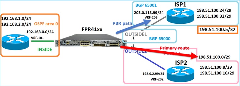
Lösung
In früheren Versionen als 7.1 PBR konfigurieren:
1. Erstellen Sie eine erweiterte ACL, die mit dem interessanten Datenverkehr übereinstimmt (z. B. PBR_ACL).
2. Erstellen Sie eine Route Map, die mit der in Schritt 1 erstellten ACL übereinstimmt, und legen Sie den gewünschten nächsten Hop fest.
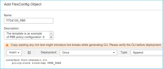
3. Erstellen Sie ein FlexConfig-Objekt, das PBR auf der Eingangsschnittstelle mithilfe der in Schritt 2 erstellten Routenübersicht aktiviert.
In Versionen nach 7.1 können Sie PBR mit der Methode vor 7.1 konfigurieren oder die neue Option "Policy Based Routing" (richtlinienbasiertes Routing) im Abschnitt "Device > Routing" (Gerät > Routing) verwenden:
1. Erstellen Sie eine erweiterte ACL, die mit dem interessanten Datenverkehr übereinstimmt (z. B. PBR_ACL).
2. Fügen Sie eine PBR-Richtlinie hinzu und geben Sie Folgendes an:
a. Der passende Datenverkehr
b. Die Eingangsschnittstelle
c. Next-Hop
Konfigurieren des PBR (neu)
Schritt 1: Definieren einer Zugriffsliste für den entsprechenden Datenverkehr

Schritt 2 - Hinzufügen einer PBR-Richtlinie
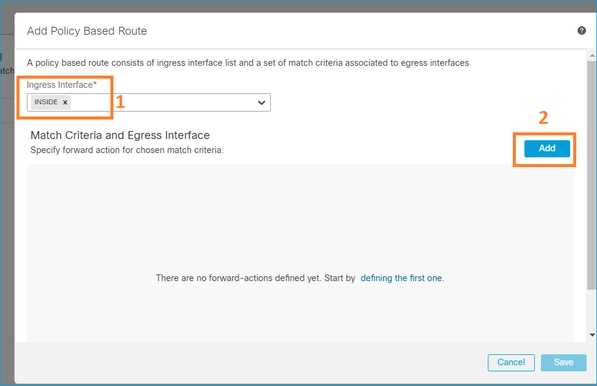
Navigieren Sie zu Devices > Device Management (Geräte > Geräteverwaltung), und bearbeiten Sie das FTD-Gerät. Wählen Sie Routing > Policy Based Routing aus, und wählen Sie auf der Seite Policy Based Routing die Option Add aus.

Geben Sie die Eingangsschnittstelle an:
Geben Sie die Weiterleitungsaktionen an:
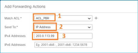
Speichern und Bereitstellen.
Hinweis: Wenn Sie mehrere Ausgangsschnittstellen konfigurieren möchten, müssen Sie im Feld "Senden an" die Option "Ausgangsschnittstellen" (verfügbar ab Version 7.0+) festlegen. Weitere Informationen finden Sie unter Konfigurationsbeispiel für richtlinienbasiertes Routing.
Konfigurieren des PBR (Legacy-Modus)
Schritt 1: Definieren einer Zugriffsliste für den entsprechenden Datenverkehr

Schritt 2: Definieren einer Route Map, die der ACL entspricht und den Next Hop festlegt
Definieren Sie zunächst die Übereinstimmungsklausel:
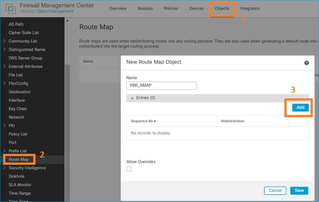
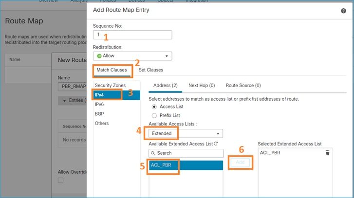
Definieren Sie die Set-Klausel:
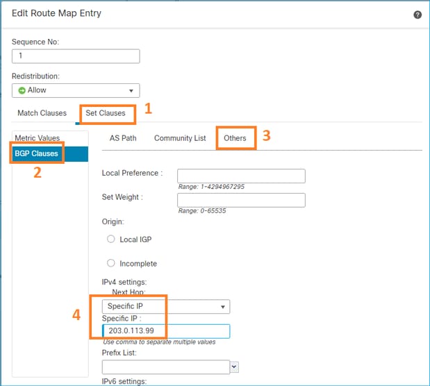
Hinzufügen und Speichern.
Schritt 3: Konfigurieren Sie das PBR-Objekt FlexConfig.
Kopieren (duplizieren) Sie zunächst das vorhandene PBR-Objekt:

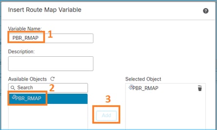
Geben Sie den Objektnamen an, und entfernen Sie das vordefinierte route-map-Objekt:
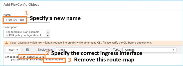
Geben Sie die neue Routenübersicht an:
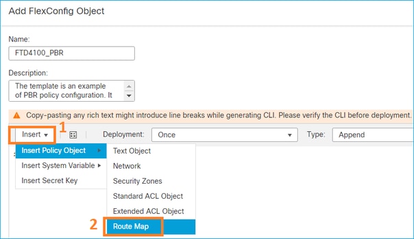
Dies ist das Endergebnis:
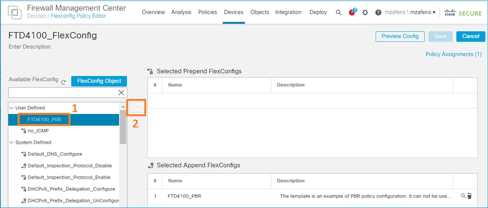
Schritt 4: Fügen Sie der FTD-FlexConfig-Richtlinie das PBR-Objekt hinzu.
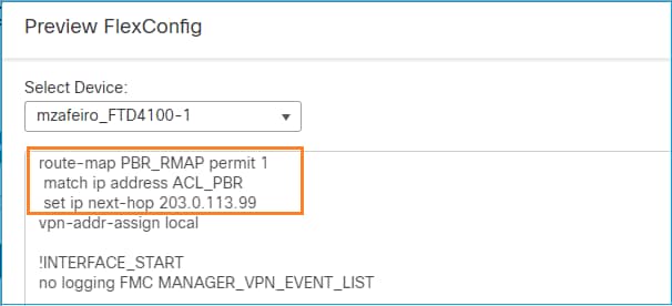
Speichern und Konfigurationsvorschau auswählen:

Stellen Sie abschließend die Richtlinie bereit.
Hinweis: PBR kann nicht mit FlexConfig und der FMC-Benutzeroberfläche für dieselbe Eingangsschnittstelle konfiguriert werden.
Informationen zur PBR-SLA-Konfiguration finden Sie in diesem Dokument: Konfigurieren Sie PBR mit IP SLAs für DUAL ISP auf FTD Managed by FMC
PBR-Verifizierung
Verifizierung der Eingangsschnittstelle:
firepower# show run interface Po1.101
!
interface Port-channel1.101
vlan 101
nameif INSIDE
cts manual
propagate sgt preserve-untag
policy static sgt disabled trusted
security-level 0
ip address 192.168.0.1 255.255.255.0
policy-route route-map FMC_GENERATED_PBR_1649228271478
ospf authentication null
Route-Map-Verifizierung:
firepower# show run route-map
!
route-map FMC_GENERATED_PBR_1649228271478 permit 5
 match ip address ACL_PBR
 set ip next-hop 203.0.113.99
firepower# show route-map
route-map FMC_GENERATED_PBR_1649228271478, permit, sequence 5
Match clauses:
ip address (access-lists): ACL_PBR

Set clauses:
adaptive-interface cost OUTSIDE1 (0)
Policy-Route-Verifizierung:
firepower# show policy-route
Interface Route map
Port-channel1.101 FMC_GENERATED_PBR_1649228271478
Packet-Tracer vor und nach der Änderung:
| Ohne PBR | Mit PBR |
firepower# packet-tracer input INSIDE tcp 192.168.2.100 1111 198.51.100.5 23 |
firepower# packet-tracer input INSIDE tcp 192.168.2.100 1111 198.51.100.5 23 |
Testen mit echtem Datenverkehr
Konfigurieren Sie die Paketerfassung mit einer Ablaufverfolgung:
firepower# capture CAPI trace interface INSIDE match ip host 192.168.2.1 host 198.51.100.5
firepower# capture CAPO1 trace interface OUTSIDE1 match ip host 192.168.2.1 host 198.51.100.5
firepower# capture CAPO2 trace interface OUTSIDE2 match ip host 192.168.2.1 host 198.51.100.5
Router1# telnet 198.51.100.5 /vrf VRF-101 /source-interface lo2
Trying 198.51.100.5 ... Open
Die Aufzeichnung zeigt Folgendes:
firepower# show capture
capture CAPI type raw-data trace interface INSIDE [Capturing - 4389 bytes]
match ip host 192.168.2.1 host 198.51.100.5
capture CAPO1 type raw-data trace interface OUTSIDE1 [Capturing - 4389 bytes]
match ip host 192.168.2.1 host 198.51.100.5
capture CAPO2 type raw-data trace interface OUTSIDE2 [Capturing - 0 bytes]
match ip host 192.168.2.1 host 198.51.100.5
Nachverfolgung des TCP-SYN-Pakets:
firepower# show capture CAPI packet-number 1 trace

44 packets captured

1: 13:26:38.485585 802.1Q vlan#101 P0 192.168.2.1.49032 > 198.51.100.5.23: S 571152066:571152066(0) win 4128 <mss 536>
...

Phase: 3
Type: SUBOPTIMAL-LOOKUP
Subtype: suboptimal next-hop
Result: ALLOW
Elapsed time: 13826 ns
Config:
Additional Information:
Input route lookup returned ifc OUTSIDE2 is not same as existing ifc OUTSIDE1

Phase: 4
Type: ECMP load balancing
Subtype:
Result: ALLOW
Elapsed time: 1784 ns
Config:
Additional Information:
ECMP load balancing
Found next-hop 203.0.113.99 using egress ifc OUTSIDE1(vrfid:0)

Phase: 5
Type: PBR-LOOKUP
Subtype: policy-route
Result: ALLOW
Elapsed time: 446 ns
Config:
route-map FMC_GENERATED_PBR_1649228271478 permit 5
match ip address ACL_PBR
set adaptive-interface cost OUTSIDE1
Additional Information:
Matched route-map FMC_GENERATED_PBR_1649228271478, sequence 5, permit
Found next-hop 203.0.113.99 using egress ifc OUTSIDE1

...

Phase: 15
Type: ADJACENCY-LOOKUP
Subtype: Resolve Nexthop IP address to MAC
Result: ALLOW
Elapsed time: 4906 ns
Config:
Additional Information:
Found adjacency entry for Next-hop 203.0.113.99 on interface OUTSIDE1
Adjacency :Active
MAC address 4c4e.35fc.fcd8 hits 348 reference 2

...

Result:
input-interface: INSIDE(vrfid:0)
input-status: up
input-line-status: up
output-interface: OUTSIDE1(vrfid:0)
output-status: up
output-line-status: up
Action: allow
Time Taken: 222106 ns
Die ASP-PBR-Tabelle zeigt die Anzahl der Richtlinienzugriffe an:
firepower# show asp table classify domain pbr

Input Table
in id=0x1505f26d3420, priority=2147483642, domain=pbr, deny=false
hits=7, user_data=0x1505f26e7590, cs_id=0x0, use_real_addr, flags=0x0, protocol=0
src ip/id=192.168.2.0, mask=255.255.255.0, port=0, tag=any
dst ip/id=198.51.100.5, mask=255.255.255.255, port=0, tag=any, dscp=0x0, nsg_id=none
input_ifc=INSIDE(vrfid:0), output_ifc=any

Output Table:

L2 - Output Table:

L2 - Input Table:

Last clearing of hits counters: Never
Hinweis: Der Paket-Tracer erhöht auch den Trefferzähler.
PBR-Fehlersuche
Warnung: In einer Produktionsumgebung kann das Debuggen eine Menge Nachrichten erzeugen.
Dieses Debugging aktivieren:
firepower# debug policy-route
debug policy-route enabled at level 1
Senden von echtem Datenverkehr:
Router1# telnet 198.51.100.5 /vrf VRF-101 /source-interface lo2
Trying 198.51.100.5 ... Open
Das Debugging zeigt Folgendes:
firepower#

pbr: policy based route lookup called for 192.168.2.1/37256 to 198.51.100.5/23 proto 6 sub_proto 0 received on interface INSIDE, NSGs, nsg_id=none
pbr: First matching rule from ACL(2)
pbr: route map FMC_GENERATED_PBR_1649228271478, sequence 5, permit; proceed with policy routing
pbr: policy based routing applied; egress_ifc = OUTSIDE1 : next_hop = 203.0.113.99
Hinweis: Packet-Tracer generiert auch eine Debug-Ausgabe.
Dieses Flussdiagramm kann zur Fehlerbehebung bei PBR verwendet werden:
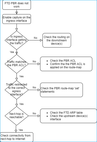
Zusammenfassung der PBR-Befehle
So überprüfen Sie die Konfiguration:
show run route-map
show run interface
Falls SLA Monitor auch mit PBR verwendet wird:
show run sla monitor
show run track
So überprüfen Sie den Vorgang:
show route-map
packet-tracer
capture w/trace (for example, capture CAPI interface INSIDE trace match ip host 192.168.0.1 host 203.0.113.50)
ASP drop capture (for example, capture ASP type asp-drop all)
show asp table classify domain pbr
show log
show arp
Falls SLA Monitor auch mit PBR verwendet wird:
show sla monitor operational-state
show sla monitor configuration
show track
PBR debuggen:
debug policy-route
show asp drop
Fall 4: Weiterleitung auf Basis der globalen Routing-Suche
Nach der Verbindungssuche, der NAT-Suche und dem PBR wird als letztes Element zur Bestimmung der Ausgangsschnittstelle die globale Routing-Tabelle überprüft.
Überprüfung der Routing-Tabelle
Lassen Sie uns eine Ausgabe der FTD-Routing-Tabelle untersuchen:
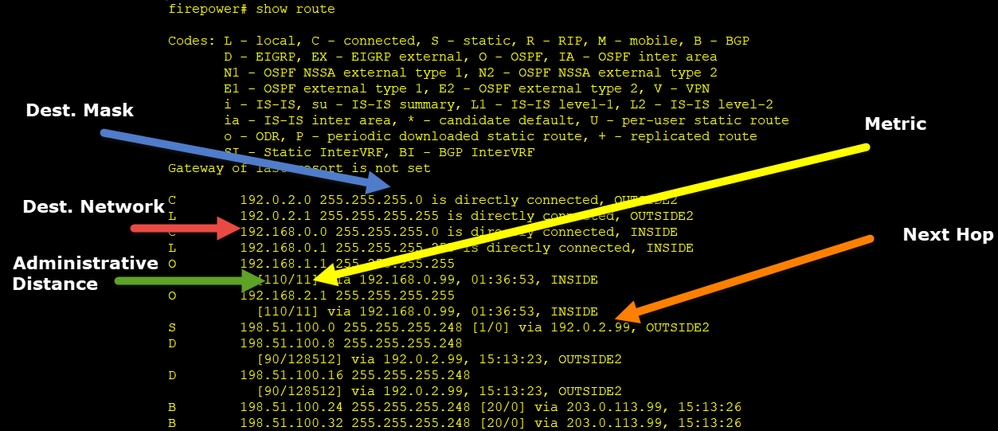
Das Hauptziel des Routing-Prozesses besteht darin, den nächsten Hop zu finden. Die Routenauswahl erfolgt in der folgenden Reihenfolge:
- Längste Übereinstimmung gewinnt
- Niedrigste AD (zwischen verschiedenen Routing-Protokollquellen)
- Niedrigste Kennzahl (falls Routen von derselben Quelle bezogen werden - Routing-Protokoll)
Auffüllen der Routing-Tabelle:
- IGP (R, D, EX, O, IA, N1, N2, E1, E2, i, su, L1, L2, ia, o)
- BGP (B)
- BGP Inter-VRF (BI)
- Statisch (S)
- Static InterVRF (SI)
- Verbunden (C)
- lokale IPs (L)
- VPN (V)
- Neuverteilung
-Standard
Verwenden Sie den folgenden Befehl, um die Zusammenfassung der Routing-Tabelle anzuzeigen:
firepower# show route summary

IP routing table maximum-paths is 8
Route Source   Networks Subnets Replicates Overhead Memory (bytes)
connected      0        8       0          704      2368
static         0        1       0          88       296
ospf 1         0        2       0          176      600
Intra-area: 2 Inter-area: 0 External-1: 0 External-2: 0
NSSA External-1: 0 NSSA External-2: 0
bgp 65000      0        2       0          176      592
External: 2 Internal: 0 Local: 0
eigrp 1        0        2       0          216      592
internal       7                                    3112
Total          7        15      0          1360     7560
Sie können die Aktualisierungen der Routing-Tabelle mit dem folgenden Befehl verfolgen:
firepower# debug ip routing
IP routing debugging is on
Dies zeigt z. B. das Debugging, wenn die OSPF-Route 192.168.1.0/24 aus der globalen Routing-Tabelle entfernt wird:
firepower#
RT: ip_route_delete 192.168.1.0 255.255.255.0 via 192.0.2.99, INSIDE
ha_cluster_synced 0 routetype 0
RT: del 192.168.1.0 via 192.0.2.99, ospf metric [110/11]NP-route: Delete-Output 192.168.1.0/24 hop_count:1 , via 0.0.0.0, INSIDE
RT: delete network route to 192.168.1.0 255.255.255.0NP-route: Delete-Output 192.168.1.0/24 hop_count:1 , via 0.0.0.0, INSIDE
NP-route: Delete-Input 192.168.1.0/24 hop_count:1 Distance:110 Flags:0X0 , via 0.0.0.0, INSIDE
Wenn er wieder hinzugefügt wird:
firepower#
RT: NP-route: Add-Output 192.168.1.0/24 hop_count:1 , via 192.0.2.99, INSIDE
NP-route: Add-Input 192.168.1.0/24 hop_count:1 Distance:110 Flags:0X0 , via 192.0.2.99, INSIDE
Null0-Schnittstelle
Die Null0-Schnittstelle kann verwendet werden, um unerwünschten Datenverkehr zu verwerfen. Dieser Verlust hat geringere Auswirkungen auf die Leistung als der Rückgang des Datenverkehrs mit einer Zugriffskontrollrichtlinie (ACL).
Anforderung
Konfigurieren Sie eine Null0-Route für einen 198.51.100.4/32-Host.
Lösung
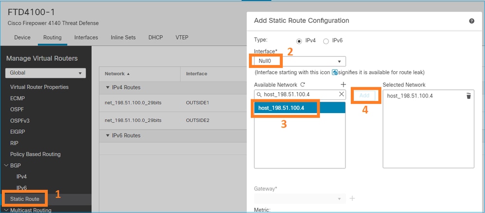
Speichern und Bereitstellen.
Überprüfen:
firepower# show run route
route OUTSIDE2 198.51.100.0 255.255.255.248 192.0.2.99 1
route OUTSIDE1 198.51.100.0 255.255.255.248 203.0.113.99 200
route Null0 198.51.100.4 255.255.255.255 1
firepower# show route | include 198.51.100.4
S 198.51.100.4 255.255.255.255 [1/0] is directly connected, Null0
Versuchen Sie, auf den Remotehost zuzugreifen:
Router1# ping vrf VRF-101 198.51.100.4
Type escape sequence to abort.
Sending 5, 100-byte ICMP Echos to 198.51.100.4, timeout is 2 seconds:
.....
Success rate is 0 percent (0/5)
Die FTD-Protokolle zeigen Folgendes:
firepower# show log | include 198.51.100.4
Apr 12 2022 12:35:28: %FTD-6-110002: Failed to locate egress interface for ICMP from INSIDE:192.168.0.99/0 to 198.51.100.4/0
ASP-Drops zeigen Folgendes:
firepower# show asp drop

Frame drop:
No route to host (no-route)                1920
Equal Cost Multi-Path (ECMP)
Verkehrszonen
- Die ECMP-Verkehrszone ermöglicht es Benutzern, Schnittstellen zusammenzufassen (auch als ECMP-Zone bezeichnet).
- Dies ermöglicht ECMP-Routing sowie Load-Balancing des Datenverkehrs über mehrere Schnittstellen hinweg.
- Wenn Schnittstellen mit der ECMP-Verkehrszone verknüpft sind, kann der Benutzer über die Schnittstellen hinweg statische Routen zu gleichen Kosten erstellen. Statische Equal-Cost-Routen sind Routen zum gleichen Zielnetzwerk mit demselben metrischen Wert.
Vor Version 7.1 unterstützte Firepower Threat Defense ECMP-Routing über FlexConfig-Richtlinien. Ab Version 7.1 können Sie Schnittstellen in Verkehrszonen gruppieren und ECMP-Routing in FirePOWER Management Center konfigurieren.
EMCP ist dokumentiert in: ECMP
In diesem Beispiel erfolgt asymmetrisches Routing, und der zurückkehrende Datenverkehr wird verworfen:
firepower# show log
Apr 13 2022 07:20:48: %FTD-6-302013: Built inbound TCP connection 4046 for INSIDE:192.168.1.1/23943 (192.168.1.1/23943) to OUTSIDE1:198.51.100.100/23 (198.51.100.100/23)
Apr 13 2022 07:20:48: %FTD-6-106015: Deny TCP (no connection) from 198.51.100.100/23 to 192.168.1.1/23943 flags SYN ACK on interface OUTSIDE2

Konfigurieren Sie ECMP über die FMC-Benutzeroberfläche:
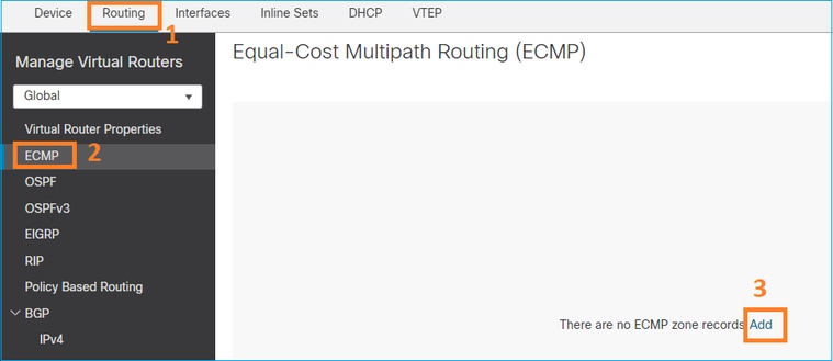
Fügen Sie die 2 Schnittstellen in der ECMP-Gruppe hinzu:
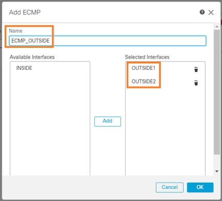
Ergebnis:

Speichern und bereitstellen
ECMP-Zonenüberprüfung:
firepower# show run zone
zone ECMP_OUTSIDE ecmp

firepower# show zone
Zone: ECMP_OUTSIDE ecmp
Security-level: 0
Zone member(s): 2
OUTSIDE1 Port-channel1.203
OUTSIDE2 Port-channel1.202
Schnittstellenüberprüfung:
firepower# show run int po1.202
!
interface Port-channel1.202
vlan 202
nameif OUTSIDE2
cts manual
propagate sgt preserve-untag
policy static sgt disabled trusted
security-level 0
zone-member ECMP_OUTSIDE
ip address 192.0.2.1 255.255.255.0

firepower# show run int po1.203
!
interface Port-channel1.203
vlan 203
nameif OUTSIDE1
cts manual
propagate sgt preserve-untag
policy static sgt disabled trusted
security-level 0
zone-member ECMP_OUTSIDE
ip address 203.0.113.1 255.255.255.0
Nun ist der zurückkehrende Datenverkehr zulässig, und die Verbindung ist aktiv:
Router1# telnet 198.51.100.100 /vrf VRF-101 /source-interface lo1
Trying 198.51.100.100 ... Open
Die Erfassung an der ISP1-Schnittstelle zeigt den ausgehenden Datenverkehr an:
firepower# show capture CAP1

5 packets captured

1: 10:03:52.620115 802.1Q vlan#203 P0 192.168.1.1.56199 > 198.51.100.100.23: S 1782458734:1782458734(0) win 4128 <mss 536>
2: 10:03:52.621992 802.1Q vlan#203 P0 192.168.1.1.56199 > 198.51.100.100.23: . ack 2000807246 win 4128
3: 10:03:52.622114 802.1Q vlan#203 P0 192.168.1.1.56199 > 198.51.100.100.23: . ack 2000807246 win 4128
4: 10:03:52.622465 802.1Q vlan#203 P0 192.168.1.1.56199 > 198.51.100.100.23: P 1782458735:1782458753(18) ack 2000807246 win 4128
5: 10:03:52.622556 802.1Q vlan#203 P0 192.168.1.1.56199 > 198.51.100.100.23: . ack 2000807246 win 4128
Die Erfassung an der ISP2-Schnittstelle zeigt den zurückfließenden Datenverkehr an:
firepower# show capture CAP2

6 packets captured

1: 10:03:52.621305 802.1Q vlan#202 P0 198.51.100.100.23 > 192.168.1.1.56199: S 2000807245:2000807245(0) ack 1782458735 win 64240 <mss 1460>
3: 10:03:52.623808 802.1Q vlan#202 P0 198.51.100.100.23 > 192.168.1.1.56199: . ack 1782458753 win 64222
FTD-Managementebene
Die FTD verfügt über 2 Managementebenen:
- Management0-Schnittstelle - Ermöglicht den Zugriff auf das FirePOWER-Subsystem
- LINA-Diagnoseschnittstelle - Zugriff auf das FTD-LINA-Subsystem
Verwenden Sie zum Konfigurieren und Überprüfen der Management0-Schnittstelle die Befehle configure network (Netzwerk konfigurieren) bzw. show network (Netzwerk anzeigen).
Andererseits bieten die LINA-Schnittstellen Zugriff auf die LINA selbst. Die FTD-Schnittstelleneinträge in der FTD RIB können als Lokale Routen angesehen werden:
firepower# show route | include L
Codes: L - local, C - connected, S - static, R - RIP, M - mobile, B - BGP
i - IS-IS, su - IS-IS summary, L1 - IS-IS level-1, L2 - IS-IS level-2
L 192.0.2.1 255.255.255.255 is directly connected, OUTSIDE2
L 192.168.0.1 255.255.255.255 is directly connected, INSIDE
L 203.0.113.1 255.255.255.255 is directly connected, OUTSIDE1
Ebenso können sie als Identitätseinträge in der ASP-Routing-Tabelle betrachtet werden:
firepower# show asp table routing | include identity
in 169.254.1.1 255.255.255.255 identity
in 192.0.2.1 255.255.255.255 identity
in 203.0.113.1 255.255.255.255 identity
in 192.168.0.1 255.255.255.255 identity
in ff02::1 ffff:ffff:ffff:ffff:ffff:ffff:ffff:ffff identity
in ff02::1:ff01:3 ffff:ffff:ffff:ffff:ffff:ffff:ffff:ffff identity
in ff02::1:ff00:1 ffff:ffff:ffff:ffff:ffff:ffff:ffff:ffff identity
in fe80::200:ff:fe01:3 ffff:ffff:ffff:ffff:ffff:ffff:ffff:ffff identity
in fd00:0:0:1::1 ffff:ffff:ffff:ffff:ffff:ffff:ffff:ffff identity
out 0.0.0.0 0.0.0.0 via 0.0.0.0, identity
out :: :: via 0.0.0.0, identity
Hauptpunkt
Wenn ein Paket über FTD eingeht und die Ziel-IP mit einer der Identitäts-IPs übereinstimmt, weiß die FTD, dass sie das Paket verbrauchen muss.
FTD LINA-Diagnose-Schnittstellen-Routing
FTD (wie eine ASA mit Code nach 9.5) verwaltet eine VRF-ähnliche Routing-Tabelle für alle Schnittstellen, die als reine Verwaltungsschnittstelle konfiguriert sind. Ein Beispiel für eine solche Schnittstelle ist die Diagnoseschnittstelle.
Obwohl FMC Ihnen (ohne ECMP) nicht erlaubt, zwei Standardrouten auf zwei verschiedenen Schnittstellen mit derselben Metrik zu konfigurieren, können Sie eine Standardroute auf einer FTD-Datenschnittstelle und eine andere Standardroute auf der Diagnoseschnittstelle konfigurieren:

Der Datenverkehr auf Datenebene verwendet das Standard-Gateway der globalen Tabelle, während der Datenverkehr auf Verwaltungsebene das Diagnose-Standard-GW verwendet:
firepower# show route management-only

Routing Table: mgmt-only
Codes: L - local, C - connected, S - static, R - RIP, M - mobile, B - BGP
D - EIGRP, EX - EIGRP external, O - OSPF, IA - OSPF inter area
N1 - OSPF NSSA external type 1, N2 - OSPF NSSA external type 2
E1 - OSPF external type 1, E2 - OSPF external type 2, V - VPN
i - IS-IS, su - IS-IS summary, L1 - IS-IS level-1, L2 - IS-IS level-2
ia - IS-IS inter area, * - candidate default, U - per-user static route
o - ODR, P - periodic downloaded static route, + - replicated route
SI - Static InterVRF, BI - BGP InterVRF
Gateway of last resort is 10.62.148.1 to network 0.0.0.0

S* 0.0.0.0 0.0.0.0 [1/0] via 10.62.148.1, diagnostic
Das Gateway der globalen Routing-Tabelle:
firepower# show route | include S\*|Gateway
Gateway of last resort is 203.0.113.99 to network 0.0.0.0
S* 0.0.0.0 0.0.0.0 [1/0] via 203.0.113.99, OUTSIDE1
Wenn Sie Datenverkehr aus dem FTD senden (Standarddatenverkehr), wird die Ausgangsschnittstelle wie folgt ausgewählt:
- Globale Routingtabelle
- Routingtabelle nur für Verwaltung
Sie können die Auswahl der Ausgangsschnittstelle überschreiben, wenn Sie die Ausgangsschnittstelle manuell angeben.
Versuchen Sie, einen Ping an das Gateway der Diagnoseschnittstelle zu senden. Wenn Sie die Quellschnittstelle nicht angeben, schlägt der Ping fehl, da FTD zunächst die globale Routing-Tabelle verwendet, die in diesem Fall eine Standardroute enthält. Wenn in der globalen Tabelle keine Route vorhanden ist, führt der FTD eine Route Lookup anhand der Routing-Tabelle durch, die nur für das Management gilt:
firepower# ping 10.62.148.1
Type escape sequence to abort.
Sending 5, 100-byte ICMP Echos to 10.62.148.1, timeout is 2 seconds:
?????
Success rate is 0 percent (0/5)
firepower# show capture CAP1 | include 10.62.148.1
1: 10:31:22.970607 802.1Q vlan#203 P0 203.0.113.1 > 10.62.148.1 icmp: echo request
2: 10:31:22.971431 802.1Q vlan#203 P0 10.1.1.2 > 203.0.113.1 icmp: host 10.62.148.1 unreachable
firepower# ping diagnostic 10.62.148.1
Type escape sequence to abort.
Sending 5, 100-byte ICMP Echos to 10.62.148.1, timeout is 2 seconds:
!!!!!
Success rate is 100 percent (5/5), round-trip min/avg/max = 1/1/1 ms
Dasselbe gilt, wenn Sie versuchen, eine Datei mit dem Befehl copy aus der LINA-CLI zu kopieren.
Bidirectional Forwarding Detection (BFD)
BFD-Unterstützung wurde für die klassische ASA-Version 9.6 hinzugefügt und nur für das BGP-Protokoll: Bidirectional Forwarding Detection Routing
Über FTD:
- BGP IPv4- und BGP IPv6-Protokolle werden unterstützt (Software 6.4).
- Die Protokolle OSPFv2, OSPFv3 und EIGRP werden nicht unterstützt.
- BFD für statische Routen wird nicht unterstützt.
Virtuelle Router (VRF)
VRF-Unterstützung wurde in Version 6.6 hinzugefügt. Weitere Informationen finden Sie in diesem Dokument: Konfigurationsbeispiele für virtuelle Router.
Zugehörige Informationen
Revisionsverlauf
| Überarbeitung | Veröffentlichungsdatum | Kommentare |
|---|---|---|
3.0 |
30-Jul-2024 |
Übersetzungsfehler des Computers entfernt
Überarbeitete Links und Groß-/Kleinschreibung, Alternativtext
Aktualisierte Stilanforderungen |
2.0 |
07-Jun-2023 |
Entfernte PII
Alternativtext hinzugefügt
Aktualisierte Stilanforderungen und SEO-Formatierung |
1.0 |
14-Apr-2022 |
Erstveröffentlichung |
Beiträge von Cisco Ingenieuren
- Ilkin GasimovCustomer Delivery Engineering Technical Leader
- Mikis ZafeiroudisCustomer Delivery Engineering Technical Leader
Cisco kontaktieren
- Eine Supportanfrage öffnen

- (Erfordert einen Cisco Servicevertrag)
 Feedback