Cisco Intersight Storage Best Practices Configuration Guide
Available Languages
Bias-Free Language
The documentation set for this product strives to use bias-free language. For the purposes of this documentation set, bias-free is defined as language that does not imply discrimination based on age, disability, gender, racial identity, ethnic identity, sexual orientation, socioeconomic status, and intersectionality. Exceptions may be present in the documentation due to language that is hardcoded in the user interfaces of the product software, language used based on RFP documentation, or language that is used by a referenced third-party product. Learn more about how Cisco is using Inclusive Language.
This guide outlines various storage configurations and best practices for Cisco Intersight® Managed Mode (IMM) with Cisco UCS® fabric interconnect ̶ attached servers, as well as Cisco Intersight Standalone Mode (ISM). It covers best practices for local storage and storage protocols, such as SAN and NVMe over Fabrics, iSCSI boot and OS driver installation.
Knowing how to create domain and server profiles in Intersight is essential, because these topics are not covered in this document. Operating system configuration examples are not included in this document, but links to official vendor configuration resources are provided.
Before starting a storage configuration in Intersight, please make sure your current hardware configuration supports it.
To verify this, use the Hardware Compatibility List (HCL).
Here is a link to the online HCL: https://ucshcltool.cloudapps.cisco.com/public/.
The usage of this technical configuration guide is not limited to storage administrators, Intersight administrators, or server administrators who are seeking guidance on storage configurations.
All readers must have configuration knowledge of operating systems such as Linux and Windows, along with a solid understanding of their components and of Cisco Intersight.
All configurations in this document use Cisco Intersight as the management tool to configure Cisco UCS servers.
Intersight provides a capability to use templates that make it easier to clone profiles.
This is a best practice for Intersight.
For the sake of simplicity, this document will show only profiles and policies.
When a Cisco UCS server is connected to a Fabric Interconnect (FI), the FI should be configured with a domain profile that contains its settings. Servers operating in either Intersight Managed Mode (IMM) or Intersight Standalone Mode (ISM) should have a server profile applied to configure their settings.
Before creating the server profiles, create a domain profile and apply it to the fabric interconnect.
Policies can be embedded and direct attached to this profile. In Figure 1 is an overview of all the policies that can be configured in the domain profile.
In the rest of this document, policies that need to be changed from default values to a different value are marked in green.
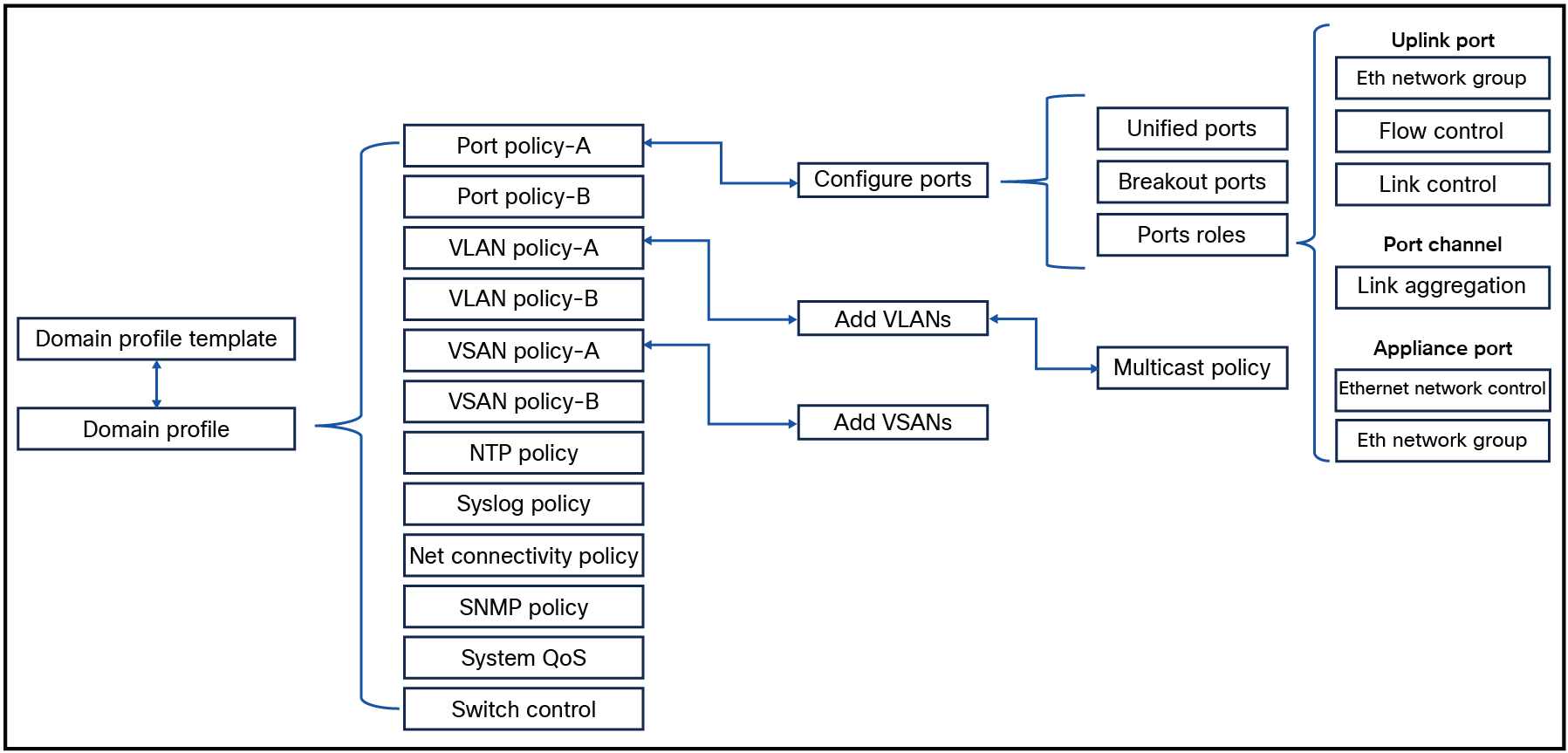
Overview of all policies within a domain profile.
Using a profile template is a best practice, even if your current need is for only one server profile. Working with server profile templates makes it possible to create new server profiles from this template if they are needed. This will save time.
A server profile template consists of policies that can be defined before creating or during the creation of a server profile template.
Figure 2 shows policies that can be used in a server profile template. Policies can have embedded policies. Some policies are direct-attached and some are embedded.
In this document all of the policies that must be changed for a particular storage profile from the default to different values will be marked in green.
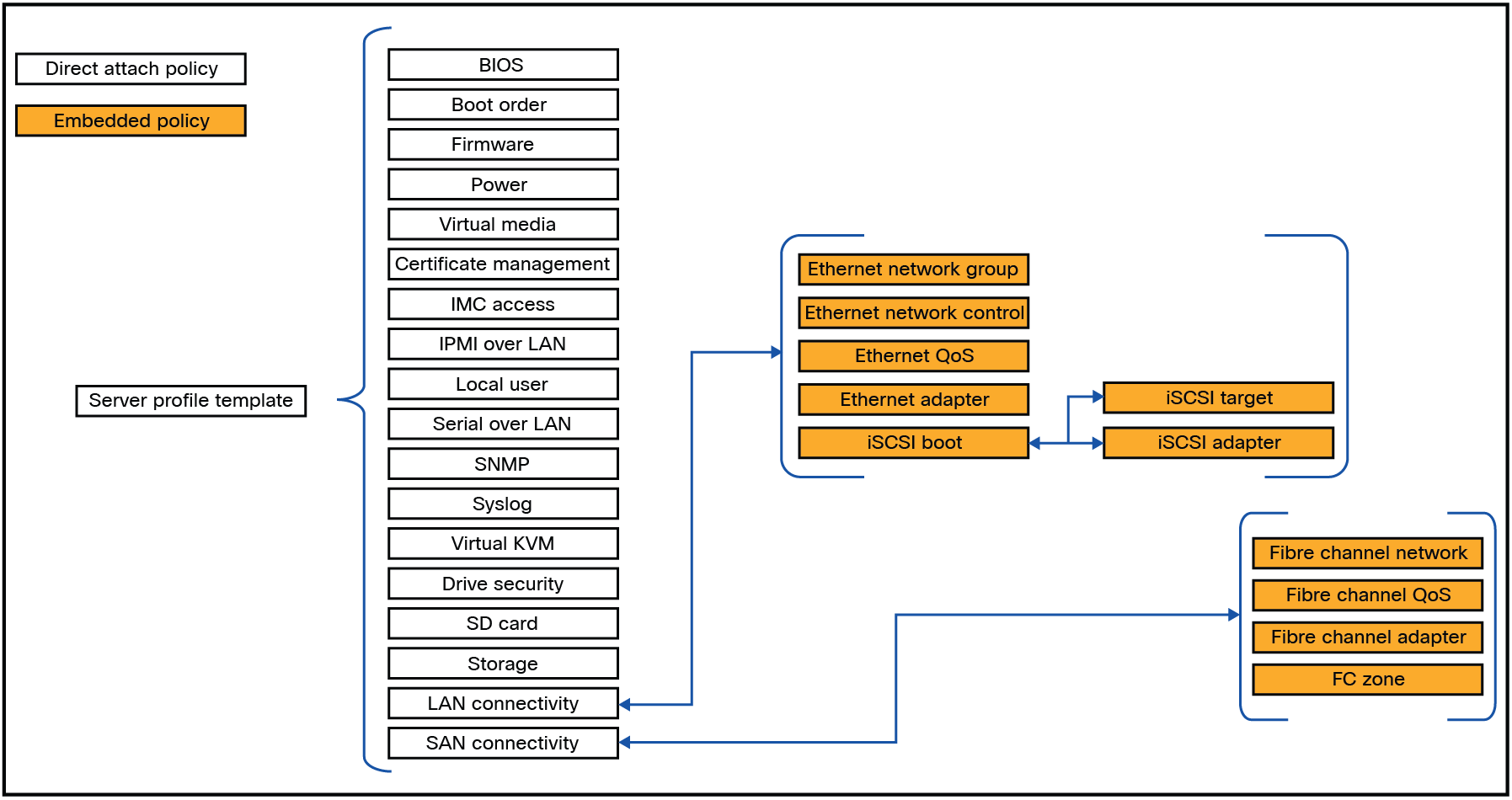
Overview of all policies within a server profile template.
In a Cisco UCS server, several types of drives are available, each utilizing different protocols and form factors.
This document does not cover the specifics of storage protocols or drive form factors. The choice of RAID configuration depends on the specific use case. For detailed explanations of different RAID types, please refer to the Cisco UCS Servers RAID Guide.
Note that not all RAID types are compatible with every configuration scenario.
Local storage configuration is discussed next.
For the following sections, change the storage policy and/or the boot order.
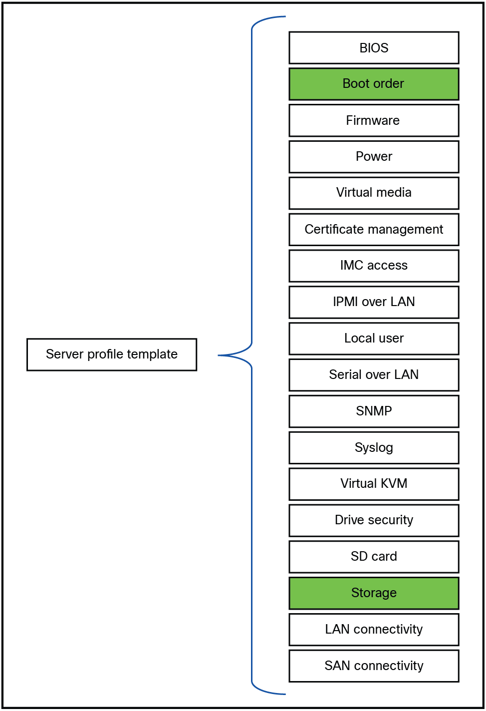
Policies that has to be changed for local storage configuration.
One of the popular boot mechanisms is to have an M.2 boot drive configured. Two M.2 drives can be inside of a Cisco UCS server.
Looking at the inventory of the server, you will see a list of available storage controllers.
An MSTOR-RAID is a M.2 hardware RAID controller. After clicking this controller, you will see the information about the controller.
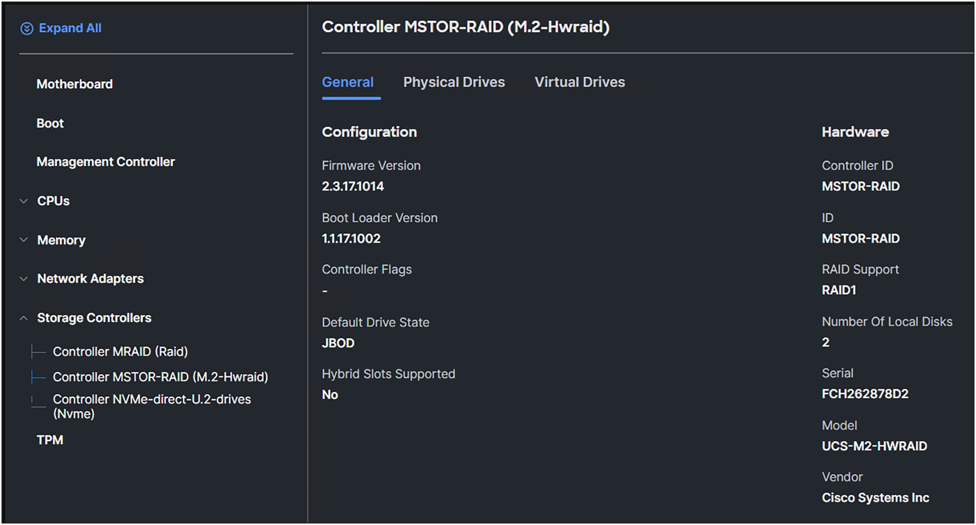
M.2 RAID controller information.
Clicking on the Physical Drives will provide a list of the drives with information for each drive.
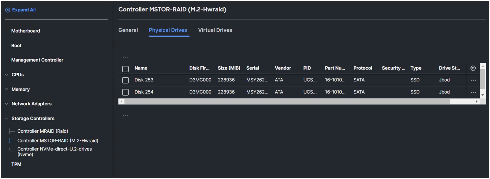
Physical drives connected to the M.2 RAID controller.
The Virtual Drives tab shows the virtual drives created from the M.2 drives.
In this example, there are no configurations yet.
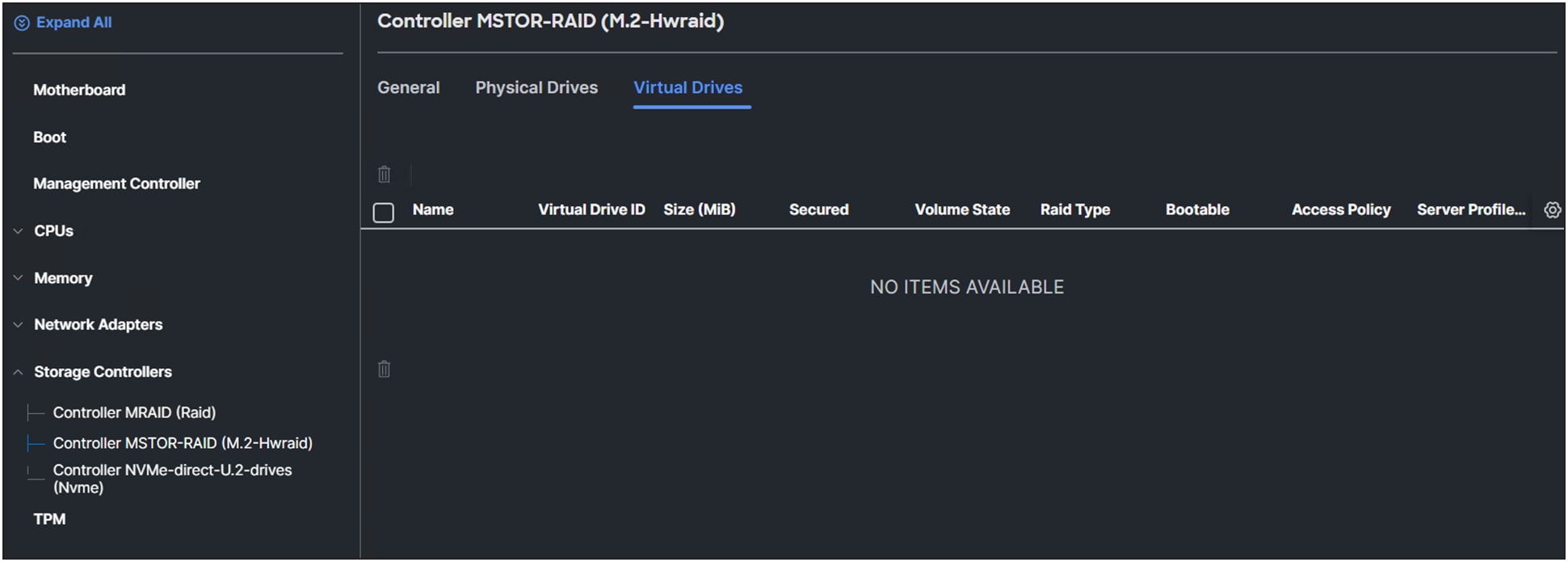
Overview of the virtual drives of the M.2 RAID controller.
Configuration of the M.2 drives in IMM
1. Create a storage policy.
2. Select a Cisco UCS server (FI-attached) and enable the M.2 RAID controller.
3. Add a name for the Virtual Drive Name or leave it as the default (MStorBootVd).
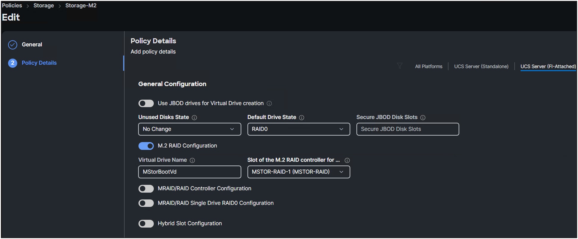
Storage policy details.
4. Select a “Slot of the M.2 RAID controller for…”. (See Figure 7.)
Only a Cisco UCS B200 M6 Blade Server has the option to have two M.2 controllers (MSTOR-RAID-2).
For a Cisco UCS C-Series server or a Cisco UCS X-Series compute node, select MSTOR-RAID-1.
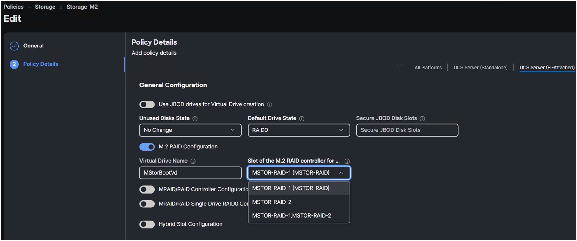
Selection of M.2 RAID controllers.
Best practice is to have two disks in RAID1 as a boot drive.
When creating the server profile, at the storage configuration, select the storage policy that was created in the above steps.
Figure 9 shows the storage policy in the UCS Server Profile.
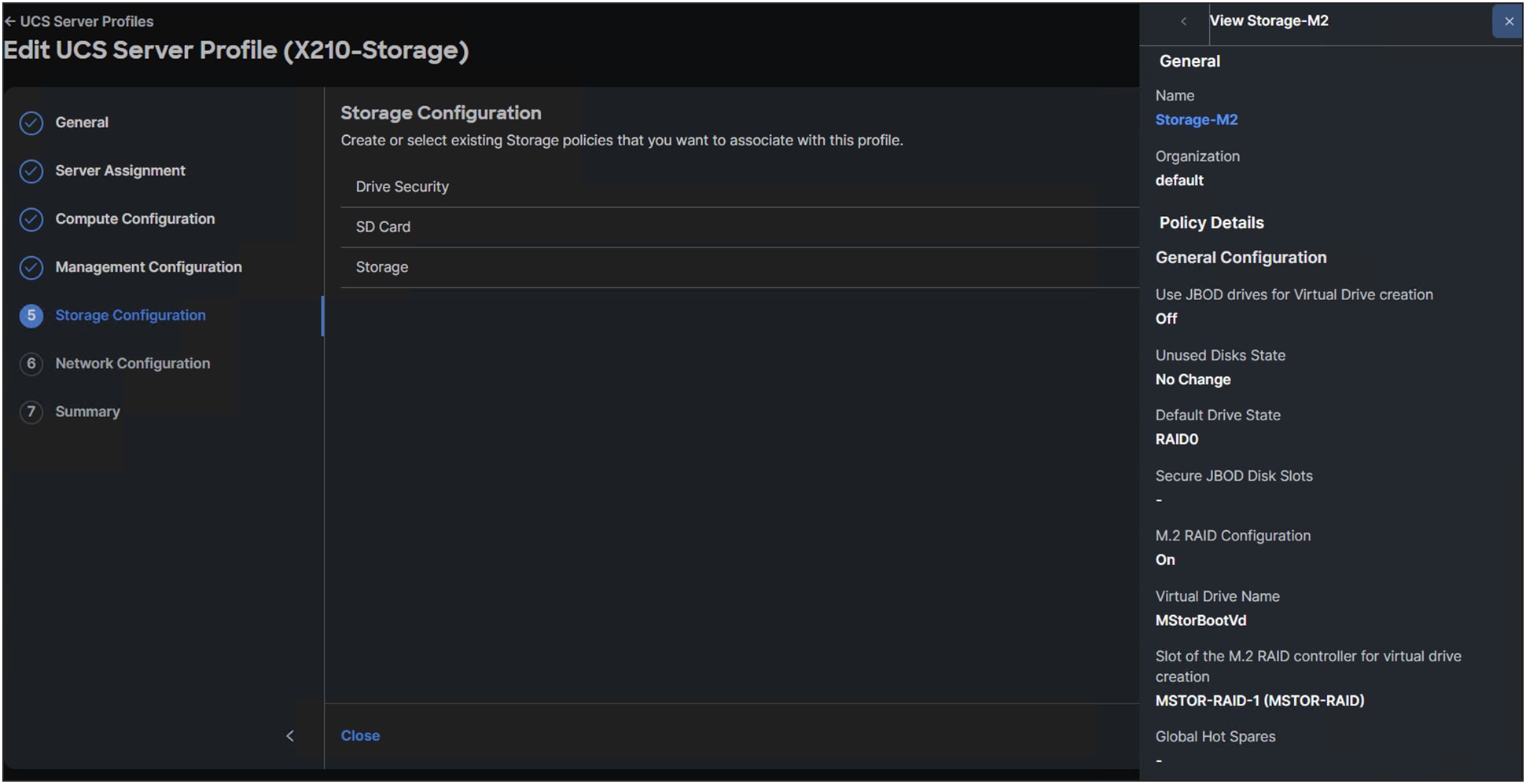
Storage policy information.
Figure 10 shows the result when selecting the storage policy in the UCS Server Profile.

Applied storage policy to a server profile.
Once the server profile is deployed successfully, in the server inventory the virtual drive’s information can be viewed at the M.2 controller.
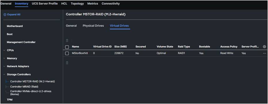
Virtuel drive after applying the storage policy to the server profile.
M.2 Cisco Intersight Standalone Mode configuration
The steps to configure M.2 drives in a standalone Cisco UCS C-Series server are the same as for an FI-connected server.
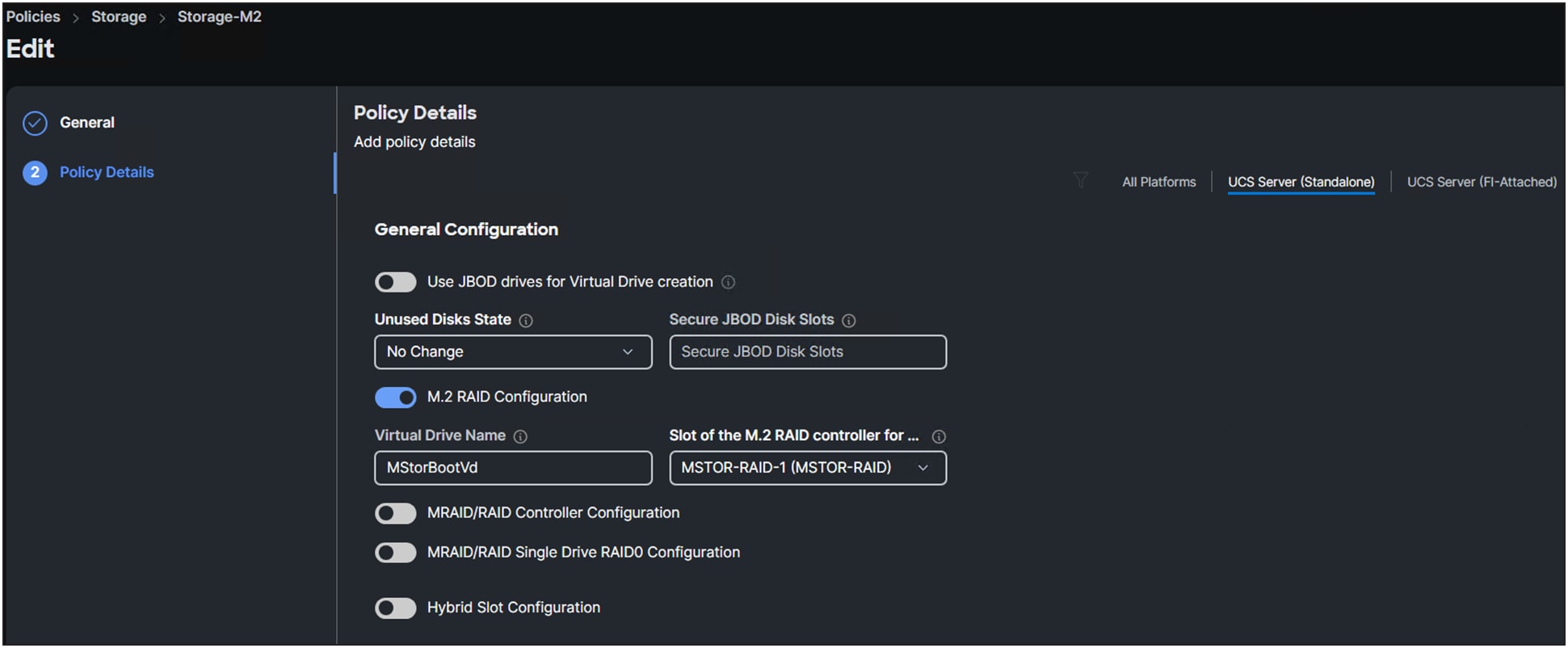
Storage policy for a Cisco UCS C-Series standalone server.
Cisco® boot-optimized M.2 and M.2 NVMe RAID controllers have the following limitations:
● Local disk configuration is not supported.
● Different M.2 capacity drives cannot be mixed.
● Renaming orphan virtual drives is not possible.
● Only RAID1 and JBOD are supported in UEFI mode. The M.2 NVMe option is a passthrough connecting the drives directly to CPU1.
Different controllers have different RAID support. Controllers that support NVMe drives with RAID configurations are called tri-mode controllers.
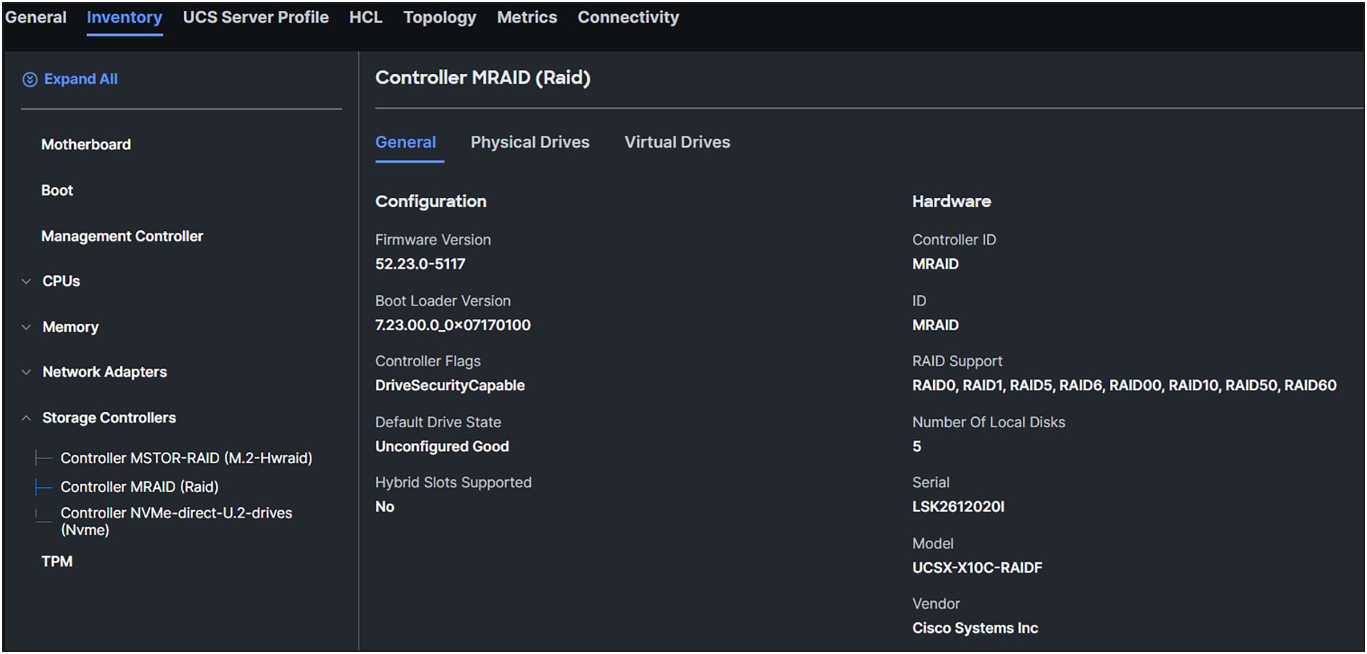
MRAID controller information.
1. Configure the storage policy and enable MRAID/RAID Controller Configuration.
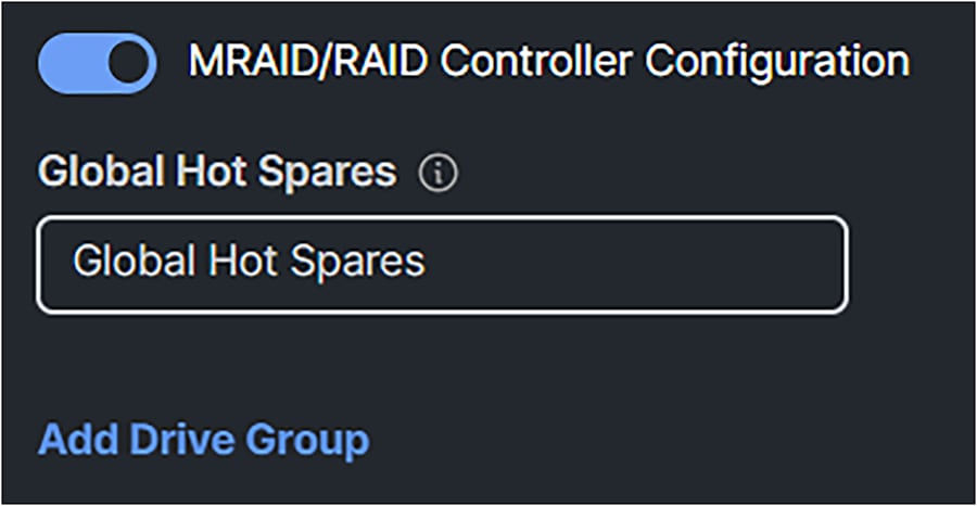
Configuration of a MRAID/RAID controller configuration.
2. Add a Drive Group. Give it a Drive Group Name, and, in this case, select RAID5 for the RAID Level.
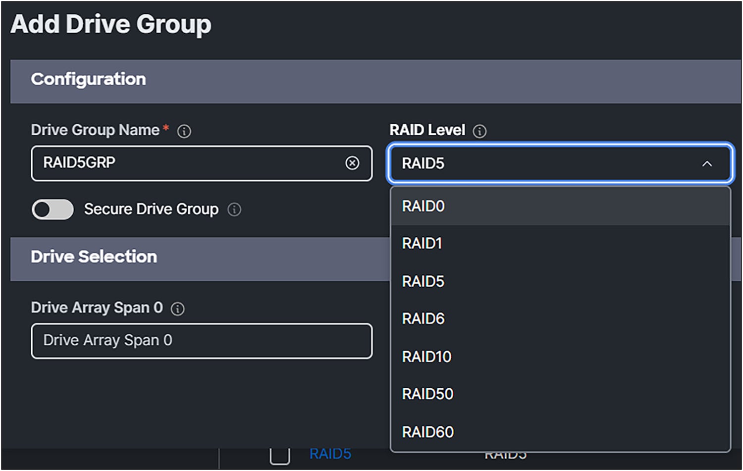
Selection of RAID Levels for the MRAID storage policy.
3. For Drive Array Span 0, select drives 3-6. In this case no Dedicated Hot Spares are being used.

Drive selection for the drive group.
4. Click Add Virtual Drive

Add virtual drive
5. Give it a Virtual Drive Name.
6. Enabling Expand to Available, will use all the disk capacity of the drives.
Size (MiB) will disappear from the box.
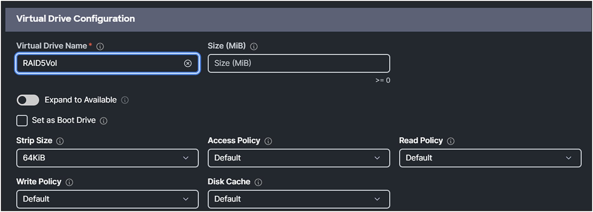
MRAID virtual drive configuration.
7. Apply the storage policy to the server profile.
Figure 19 shows how the dashboard looks like when adding the drive group and virtual drive group.
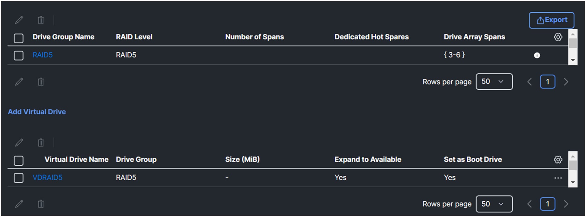
Overview of the drive groups and virtual drives after configuration.
Going back to the server inventory, expand the storage controllers. Click Controller MRAID (Raid) and then the Virtual Drives tab.
Figure 20 shows the information provided on the dashboard about the just created virtual drive on the server.

Newly create virtual drive by applying the storage policy of the MRAID controller.
Non-Volatile Memory Express (NVMe) is a protocol where devices are directly connected to the CPU through a PCIe bus. The protocol has less overhead compared to SCSI commands and provides faster storage.
There are different form factors and connectors for NVMe drives. More information about NVMe can be found on the NVM Express website.
U.3 drives
U.3 drives are built on the U.2 spec and use the same SFF-8639 connectors. They are “tri-mode” standard, combining SAS, SATA, and NVMe support in a single controller. U.3 can also support hot swaps between the different drives when the firmware support is available. U.3 drives are backward compatible with U.2, but U.2 drives are not compatible with U.3 hosts.
Source: https://en.wikipedia.org/wiki/NVM_Express#U.3_(SFF-8639_or_SFF-TA-1001).
In Figure 21, an inventory view of the physical drives attached to the Controller MRAID (Raid) is shown, with several types of drive protocols.
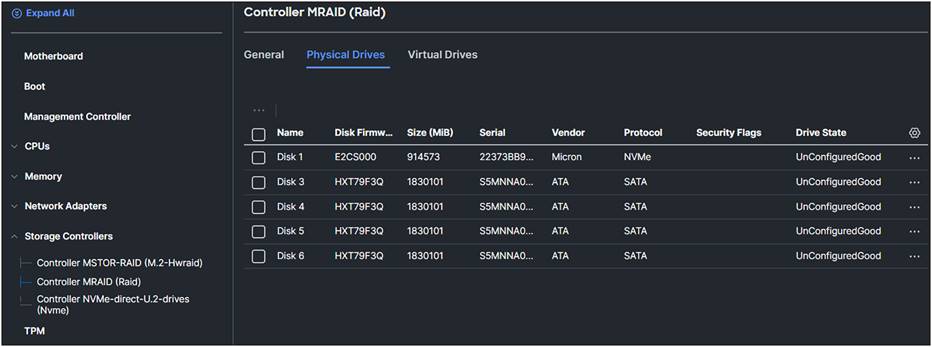
Different types of drives connected to the MRAID controller.
In the storage policy, the U.3 NVMe drive is configured as a Single RAID0 drive.

Virtual drive of the U.3 drive after MRAID configuration.
U.3 NVMe drives selected with the tri-mode RAID controller will be set, as the factory default, to RAID attached. The U.3 drives in slots 1 to 4 can, however, operate in U.2 mode; that is, directly attached to the CPU. This mode can be changed for the Cisco UCS C-Series servers in the storage policy.

Choice for the U.3 drives in the storage policy.
Only U.3 NVMe drives can be specified and moved to Direct Attached mode or RAID Attached mode.
Intel® Virtual RAID on CPU (VROC) is a software RAID controller for servers with NVMe drives without a hardware RAID controller.
Note: VROC is at this moment only supported on the Cisco UCS Rack and X-Series M6 server.
To use VROC, first enable VMD through a BIOS policy, and set the UEFI boot options. Enabling VMD provides a Surprise hot-plug and optional LED status management for PCIe SSD storage that is attached to the root port.
VMD must be enabled in the BIOS settings before the operating system is installed. If it is enabled after OS installation, the server will fail to boot.
To verify if VMD is enabled, go to the BIOS of the server. Press F1 during the booting of the server and go to the BIOS.
1. Go to Advanced and select LOM and PCIe Slot Configuration.
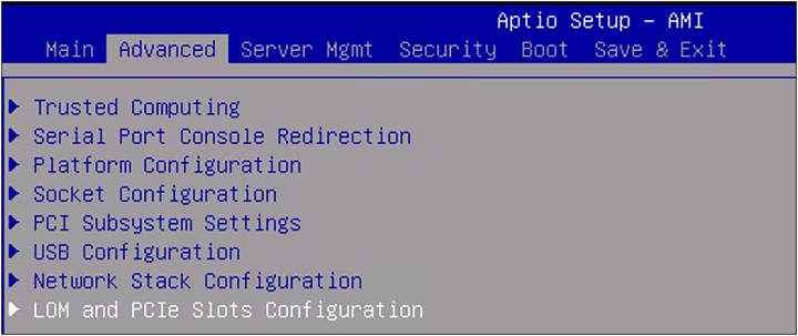
BIOS advanced settings.
2. Select PCI VMD Configuration.
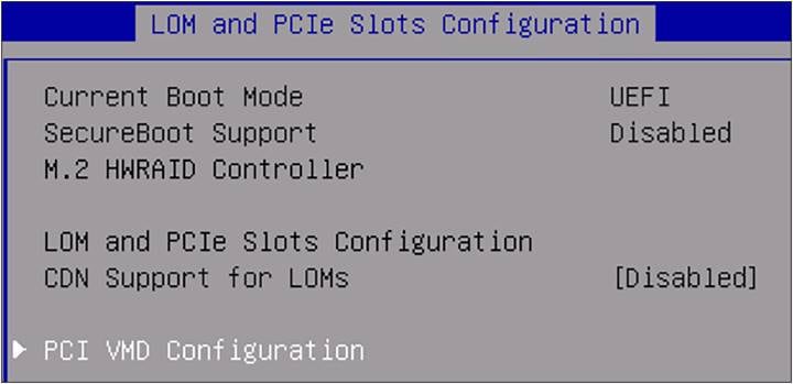
BIOS LOM and PCIe slots configuration.
The view shows that VMD is disabled. There is no possibility to enable it in this screen.

BIOS PCI VMD Configuration.
3. Create a BIOS policy with VMD Enabled.
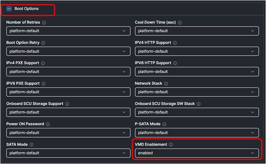
Intersight BIOS policy with VMD Enabled.
When the UCS Server Profile has the new BIOS policy, verify in the BIOS that VMD Enable is on (“[Enabled]”).

BIOS PCI VMD Configuration.
Configure Intel Virtual RAID on CPU (VROC) through the BIOS.
4. Go to Advanced and select Intel(R) Virtual RAID on CPU.
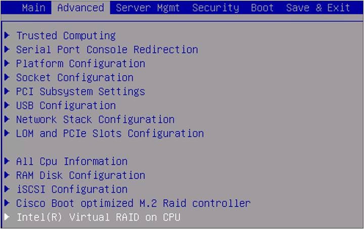
BIOS advanced setting.
At the moment, there are no RAID volumes in the system.
5. Select All Intel VMD Controllers.
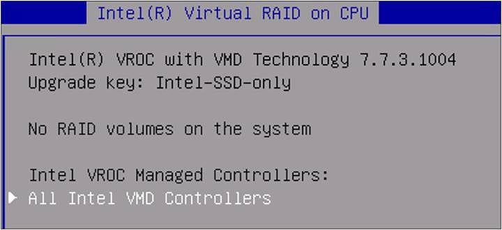
BIOS Intel® virtual RAID on CPU.
6. Select Create RAID Volume.
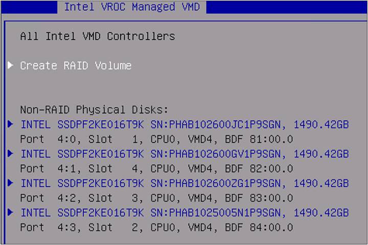
BIOS Intel VROC managed VMD.
7. Select name and give it a name. In this example it is VMD-VOL.
8. Select RAID Level, and you will see that different options are possible.
In this example, RAID5(Parity) is selected.
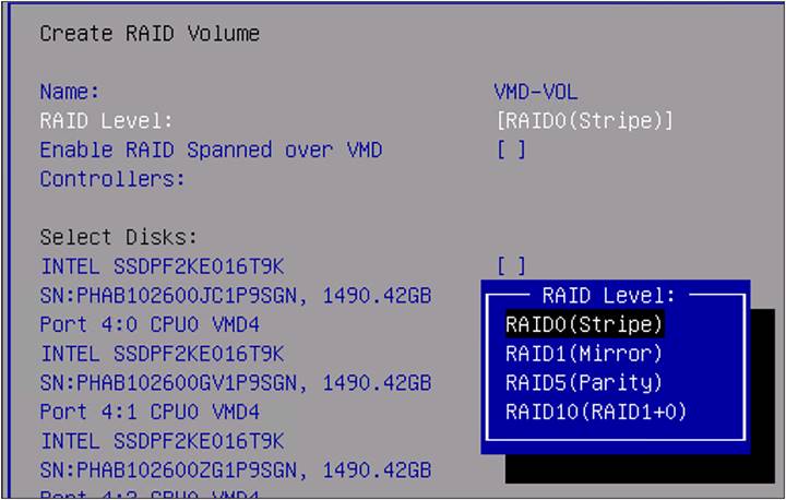
RAID level selection.
9. Select Disks that will be part of the RAID5 configuration. In this case, it is all four available drives.
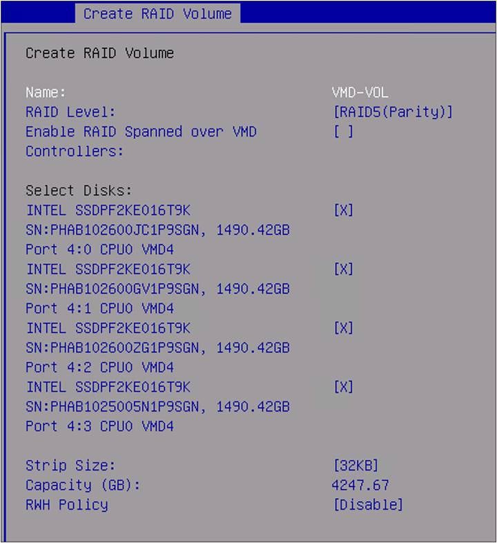
BIOS create RAID volume.
During the selection, the Capacity (GB) is updated with the usable capacity of the volume.
10. Click Create Volume at the bottom of the page.

BIOS create volume.
11. Select YES when the question is shown as in Figure 35.

BIOS create volume.
Going back in the BIOS menu, there is the volume that has just been created, with a name that states the RAID type and capacity.
12. Select the created name under RAID Volumes.
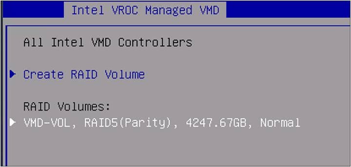
BIOS RAID volumes information.
Information about the VROC volume is displayed; to delete this volume, select delete.
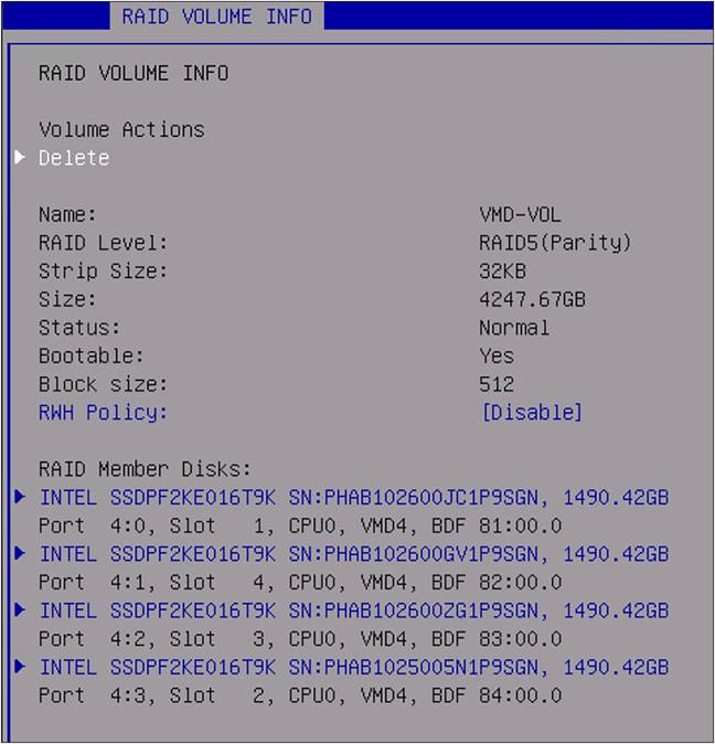
Detailed BIOS RAID volume information.
To boot from a local disk, identify the ID of the storage controller from which the server boots.
● Go to the server and select Inventory.
● Click Storage Controllers and view the storage controllers’ IDs.
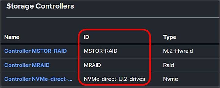
Different storage controllers in a Cisco UCS server.
● Clicking further on the storage controller will give more information about the capabilities and the number of drives.
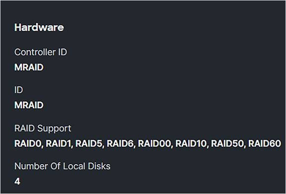
Storage controller detailed information.
SED MRAID/RAID Controller configuration
A self-encrypting drive is a drive where the data are encrypted. There are two ways to configure such a drive:
● Using Key Management Interoperability Protocol (KMIP) Server CipherTrust from Thales.
Before using KMIP, you need to get an associated certificate with Cisco IMC and the KMIP server to ensure secure communication.
This certificate can be obtained from a KMIP server.
This procedure Is not in this document and can be found in the Links to related topics.
● Have a manual security key configured.
When configuring the security key manually, the system does not save the passphrase used to create it; save the passphrase externally.
There is no means to recover the passphrase from the system.
The security key is stored with the Drive Security policy attached to the UCS Server Profile. The security key is discarded when the Drive Security policy is removed or the profile is deleted.
If the passphrase has been lost, the security key cannot be recreated or changed.
If the security key is lost, the drive data will be irrecoverably lost.
DO NOT remove the Drive Security policy or delete the UCS Server Profile if the passphrase has been lost.
To recover from a lost passphrase, before creating a new security key back up the data from the drive (which securely erases the drive) and then recover the backup.
For both options, the following policies must be updated:
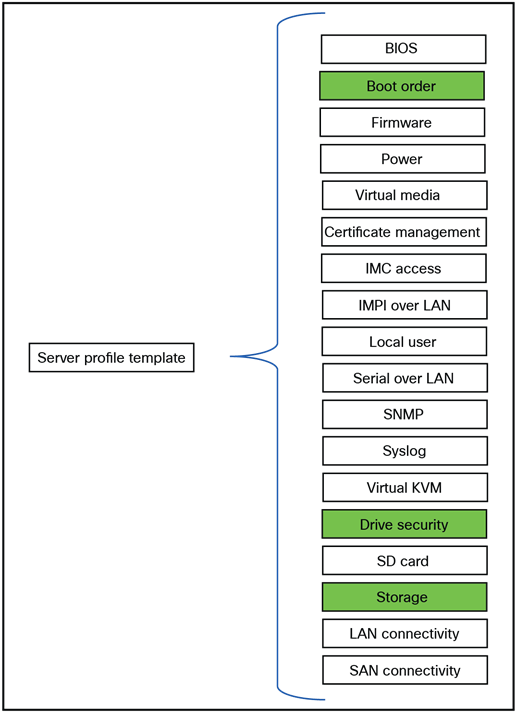
Server profile template policies that will be changed for SED configuration.
The following security flags are possible:
1. Locked — The drive, initially locked in the primary server, is transferred to the current server. To access the data, the drive must be unlocked by either entering the manual security key or reconnecting to the original KMIP key management server.
● Foreign — The drive, previously configured with virtual drives in the primary server, is relocated to the current server. Import the configuration to preserve and access the original virtual drive data. If these virtual drives must be secured, unlock the physical drives before importing the foreign configuration.
● Unencrypted — The drive can be encrypted but is currently not encrypted.
● Unlocked — The drive is currently encrypted, but the data is accessible to the user unencrypted.
Figure 41 shows an unconfigured SED Drive inventory with the security flag Unencrypted.
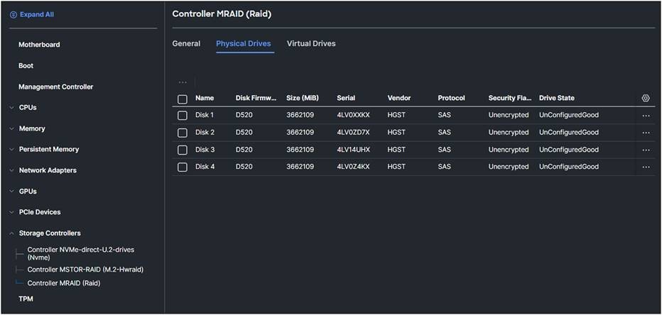
MRAID controller physical drives overview.
Configure drive security manually
1. Create a Drive Security Policy and apply this policy to the server profile.

Drive security configuration with manual key.
2. Create a storage policy.
3. Enable MRAID/RAID Controller configuration.
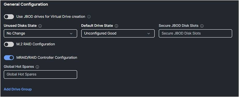
Storage profile for SED.
4. Add Drive Group with RAID Level and Drive Array Span.
5. Enable Secure Drive Group.
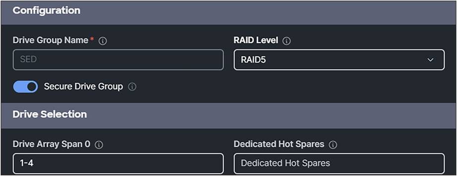
Storage profile with secure drive group enabled.
6. Add a virtual drive.

Storage profile drive group information.
7. Set the Virtual Drive Name and configure the parameters.
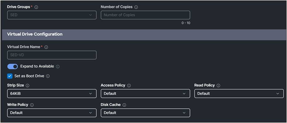
Storage profile virtual drive configuration.
This will result in the following storage policy:
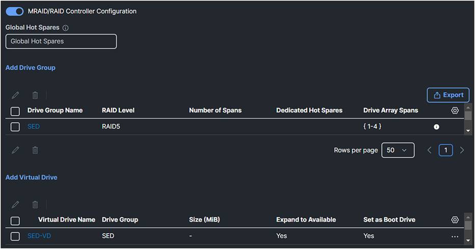
Overview of the drive group and virtual drive for SED configuration.
After applying the UCS Server Policy, view the server inventory / storage controllers and select Controller MRAID (Raid).
1. Click the Physical Drives tab.
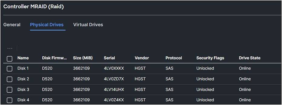
MRAID physical drive overview after applying storage profile for SED with manual key.
Because the drive security is created manually, the security flags are “Unlocked.”
2. Click the Virtual Drives tab.
The “Secured” parameter is now Yes.

MRAID virtual drives overview after applying storage profile for SED with manual key.
Configuration of SED with CipherTrust Manager from Thales
To enable drive security in Intersight with KMIP server CipherTrust, have a look at: this document.
Before diving into this configuration, here are the different supported external storage connectivities and topologies.
The legend for the following figures is:

Legend for the figures
● FC storage traffic is a Fibre Channel connection for SAN connectivity.
● Network traffic is ethernet connection for LAN connectivity.
● Storage and network traffic is traffic moving over the unified fabric through the fabric interconnect to a Cisco UCS X-Series chassis or Intersight Managed Mode Cisco UCS C-Series server.
External Fibre Channel SAN connectivity
Fibre Channel SANs have two separate paths, called SAN-A and SAN-B. This gives this fabric a higher availability and resilience compared with other topologies.
Figure 51 shows the recommended topology for external storage through Fibre Channel with the fabric interconnect in FC End-Host mode.
FC SAN and NVMe over FC are supported.
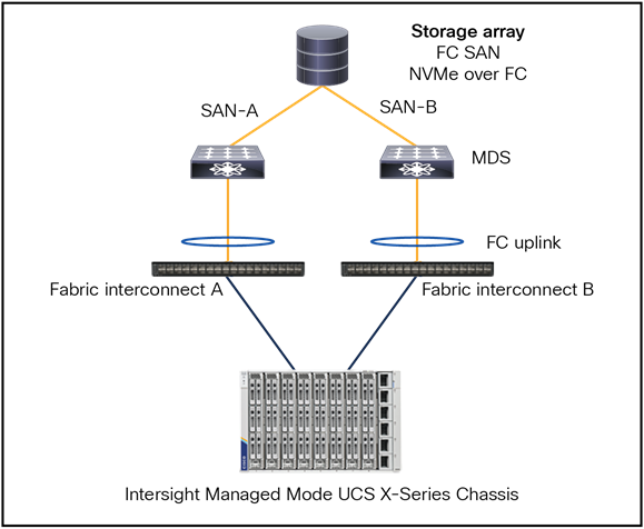
Fibre Channel topology with fabric interconnect in FC end-host mode.
The server connected to the fabric interconnect has a vHBA configured in the UCS Server Profile.
From the server to the fabric interconnect is a unified fabric, where fibre channel and ethernet traffic are going over the same physical cable.
The physical connection from the fabric interconnect to the MDS is fibre channel and from the MDS to the Storage Array is fibre channel.
Note:
● The fabric interconnect is in FC end-host mode (N-port on FI and F-ports on the MDS switches).
● SAN port-channel from the fabric interconnect to MDS is possible and optional.
● The port channel is for high availability and bandwidth aggregation.
● VSAN carries into MDS SAN with VSAN trunking.
● Best practice is to have 4 vHBAs per server, for higher redundancy.
Figure 52 shows a recommended topology when the fabric interconnect is in FC Switch Mode.
The MDS switches control the zoning, and the fabric interconnect has E-ports to the MDS.
The protocols that support it are FC SAN and NVMe over FC.
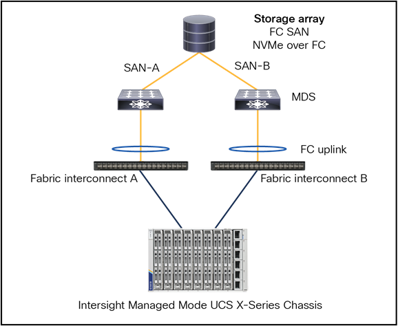
Fibre Channel topology with fabric interconnect in FC switch mode.
Note:
● The fabric interconnect is in FC switch-mode (E-port on both).
● SAN port-channel from FI to MDS.
● Port channel is for high availability and bandwidth aggregation.
● VSAN carries into MDS SAN with VSAN trunking.
● Best practice is to have 4 vHBAs per server, for higher redundancy.
● The limit for the SAN domain is 255.
● This topology can have a storage array connected to the FI along with MDS SAN connectivity.
Figure 53 shows an external Fibre Channel SAN storage with a non-MDS FC switch, with support for FC SAN and NVMe over FC.
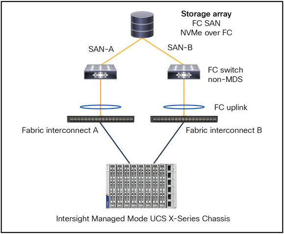
Fibre Channel topology with fabric interconnect connected to a NON Cisco MDS Switch.
Note:
● The fabric interconnect is operating in FC end-host mode.
● The configuration does not include SAN port-channels; this is recommended for non-MDS FC switches.
● VSAN virtualization is unavailable on non-MDS switches.
● For optimal redundancy, it is best practice to configure 4 vHBAs per server.
Figure 54 shows a FC direct-attached storage topology with support for FC SAN and NVMe over FC.
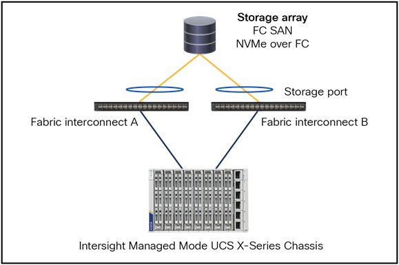
Fibre Channel topology with direct attached storage.
Note:
● The fabric interconnect is in FC switch-mode.
● The SAN port-channels are configured as storage ports and can be port channels.
● Best practice is to have 4 vHBAs per server, for higher redundancy.
Figure 55 shows an Intersight Standalone Mode connection of a UCS C-Series server with an FC connection to external storage.
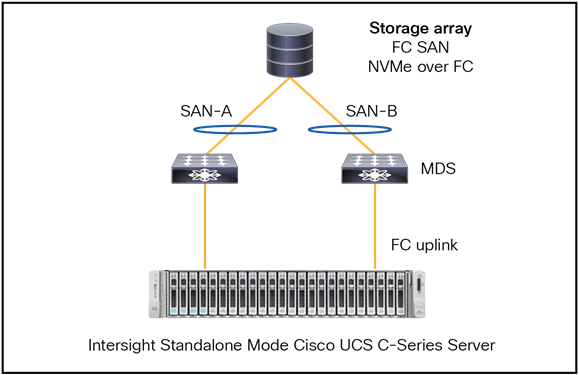
Fibre Channel topology with a standalone Cisco UCS C-Series server.
It is not possible to have the FC uplinks as port channels. The connection from the MDS to the FC SAN can have port-channels if the FC SAN supports port-channels.
There are other storage protocols that are not going over a separate fibre channel network, but over an ethernet network.
Figure 56 is a topology showing an IP SAN with Ethernet connectivity with support for iSCSI, NFS, NVMe over RoCEv2, and NVMe over TCP.
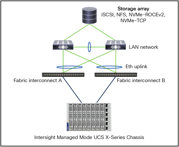
Ethernet topology for ip based storage.
Note:
● Best practice is to have virtual Port Channels (vPCs) or Multi-Chassis Trunking (MCT) port channels.
● Configure Jumbo MTU end-to-end and on all devices.
● TCP-based storage can use the QoS best-effort class but, if required, no-drop can be enabled across the fabric interconnect and top-of-rack switch.
● ROCEv2 would require no-drop QoS-class along with PFC enabled on fabric interconnect and top-of-rack switch.
● Create multiple vNICs on server for redundancy.
● Separate the storage traffic from the data traffic through different vNICs and VLANs.
● Best-practice connectivity from switches to storage is different for each vendor.
Figure 57 shows Direct-Attached Storage with an IP SAN topology.
The protocols that are supported are as follows: iSCSI, NFS, NVMe over RoCEv2, and NVMe over TCP.
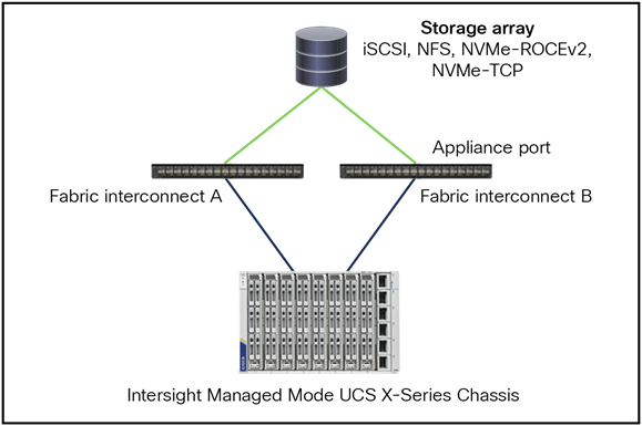
Ethernet topology with direct attached storage.
Note:
● This is only for small to medium-sized deployments.
● Configure Jumbo MTU end-to-end and on all devices.
● This solution Avoid a top-of-rack switch for storage access.
● Note that a direct port channel from a fabric interconnect to a storage controller is possible.
● Do not configure vPC like a port channel toward the storage array.
Intersight Standalone Mode
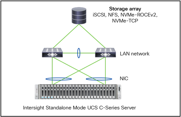
Ethernet topology with standalone Cisco UCS C-Series server.
The Cisco UCS X-Series connects to the fabric interconnect with a cable where both network and FC storage traffic flow.
This is possible because of a unique feature, called “Unified Fabric.” Multiple streams, such as FC, Ethernet, and management, go over the same physical cable.
From the fabric interconnect, the FC storage traffic is going to the Cisco MDS SAN switches. Those ports are FC ports. The network traffic from the fabric interconnect goes to the LAN switches through the network ports.
The standalone server has a Fibre Channel HBA card, which connects the physical server to the MDS SAN switches.
Before configuring the SAN connection in Intersight, follow the guidelines and recommendations that apply to all of the named VSANs, including storage VSANs.
Note:
● VSAN 4079 is a reserved VSAN ID. Do not configure a VSAN as 4079.
● This VSAN is reserved and cannot be used in either FC switch-mode or FC end-host mode. If you use 4079 as the ID for a VSAN that you name, Intersight will mark that VSAN with an error and raise a fault.
● When the fabric interconnects are in FC end-host mode, enabling Fibre Channel uplink trunking renders nonoperational all of the VSANs that have an ID from 3840 to 4079. Intersight marks each of those VSANs with an error, raising a fault for each.
● When creating an FC Zone policy for a VSAN, you must set the VSAN scope to Storage.
SAN port-channels aggregate multiple physical interfaces into one logical interface to provide more bandwidth, load balancing, and link redundancy.
Besides configurating the fabric interconnect in Intersight, configure the connected MDS switch with the correct zoning. At the end of this document, there is a link to how to configure the MDS with port channels.
Follow the following steps to configure SAN port-channels.
1. Create a new Port Policy for the Domain Policy.
2. Adjust the Unified Ports, if needed.
3. Configure the Breakout Options, if needed.
4. Configure the Port Roles, if needed.
5. To configure the FC Port Channels, the port should be unconfigured.
6. Click Port Channels and Create Port Channel.

Domain profile SAN port channel creation.
7. Select FC Uplink Port Channel as Role.
8. Give it a Port Channel ID.
9. Configure the VSAN ID.
And select the unconfigured FC ports that are in the SAN port-channels.
Apply this policy to the domain policy that is attached to the FI.
Note that it is best practice to have two different port policies, one for SAN-A with the correct VSAN, and one for SAN-B with the other VSAN.
The FC uplinks balance automatically when FC port channels are utilized.
Note: Fibre Channel port channels are not compatible with technology that is not from Cisco.
UCS Server Profile SAN connectivity policy
After the configuration of the FC ports or FC port channels in the domain policy, create the SAN connectivity policy and apply it to the UCS Server Profile.
1. Note that, in this case, the vHBAs are manually placed; Auto vHBAs Placement also is possible, if preferred. Select a WWNN Pool or create one.
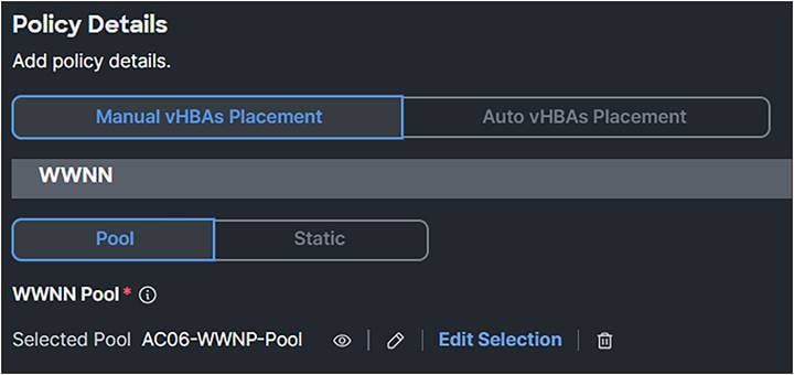
SAN connectivity policy.
2. Click Add and select vHBA.
Working with templates (for example, see Figure 61) is a best practice and saves time overall. This document does not work with templates.
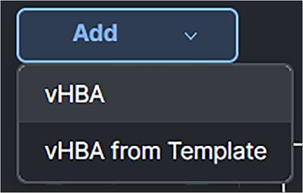
Add vHBA in SAN connection policy.
3. Give the vHBA a Name.
4. Select fc-initiator as the vHBA Type.
5. Select or Create a WWPN Pool.
Best practice is to have different WWPN pools for SAN-A and SAN-B. This makes troubleshooting easier.
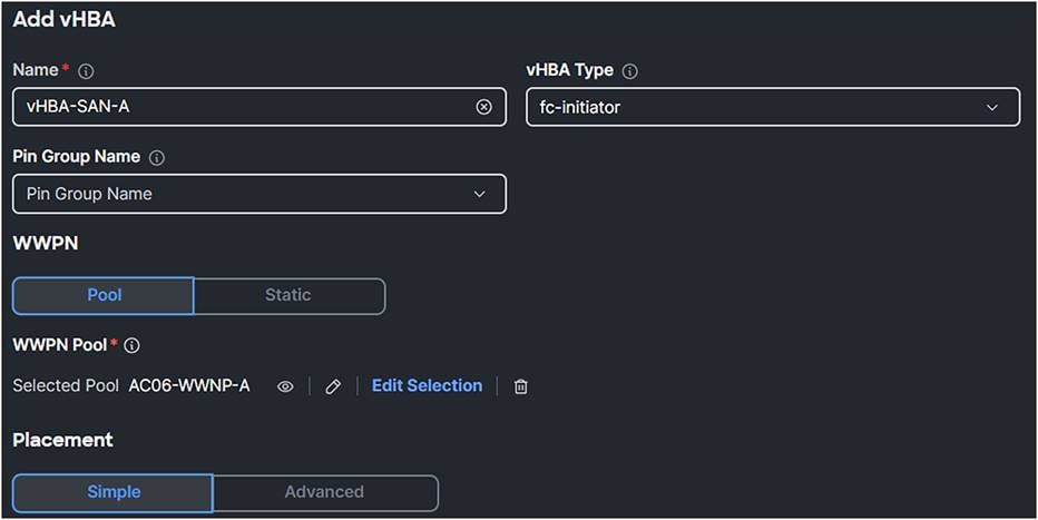
SAN connectivity policy
● Simple Placement is possible; in this case, for completion, select Placement Advanced.
● The Switch ID is the Fabric Interconnect Side where the traffic will go over.
● The PCI Order is a unique value which represents the order of the vHBA. Make sure this does not have the same value as the vNIC or the other vHBAs.
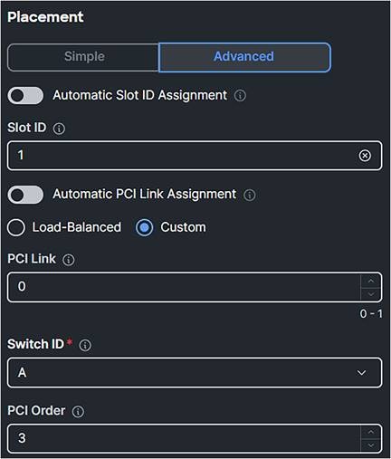
vHBA placement.
If Persistent LUN Bindings is enabled, the Fibre Channel targets are maintained after a reboot.

Persistent LUN bindings.
● Create a Fibre Channel Network Policy with SAN-A or SAN-B, depending on if the vHBA is for SAN-A or SAN-B.

Fibre Channel network.
● Create a Fibre Channel QoS Policy and make sure the Maximum Data Field Size, Bytes is 2112.

Fibre Channel QoS policy.
● Create a Fibre Channel Adapter Policy and select Initiator for predefined values.
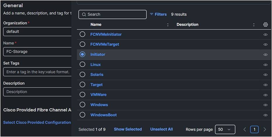
Fibre Channel adapter policy.
After clicking Next, the list of values is shown.
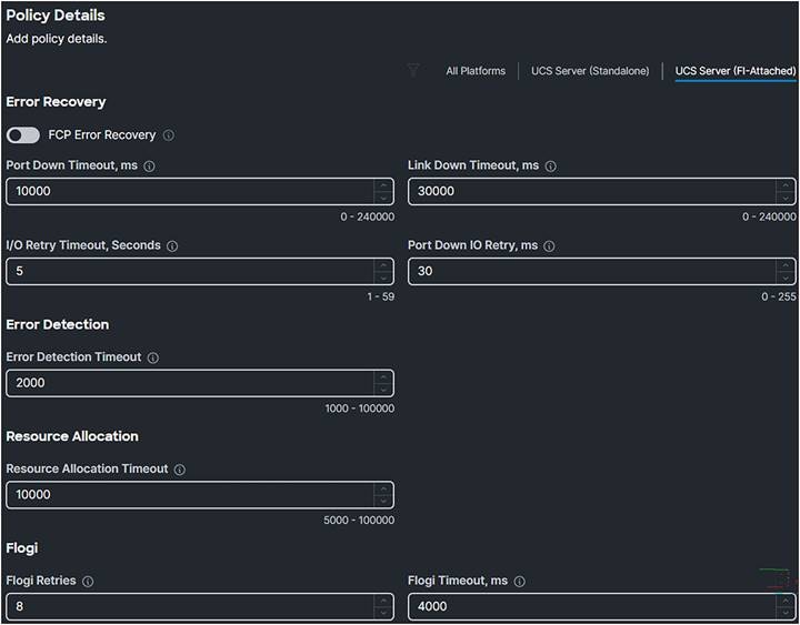
Fibre Channel adapter policy.
Figure 69 shows the results after creating the policies in the SAN Connectivity Policy.
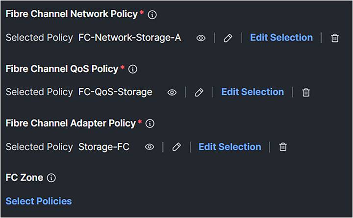
SAN connectivity policy after selecting the required policies.
Create two vHBAs. One for SAN-A and one for SAN-B.

vHBA overview in the SAN connectivity policy.
Troubleshooting FC on Cisco UCS
In the fabric interconnect, following are the commands to troubleshoot the FC connection from the server initiator to the SAN target:
1. SSH to the fabric interconnect.
2. Connect adapter x/y/z, where x/y is the server and /z is the adapter.
3. Type: attach-fls.
With the command vnic, a list of vnic/vhbas is displayed.
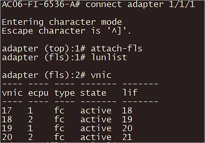
Troubleshooting on the fabric interconnect.
With the command lunlist information about the FLOGI and PLOGI status of the vnic/vhba is displayed, as in Figure 72.
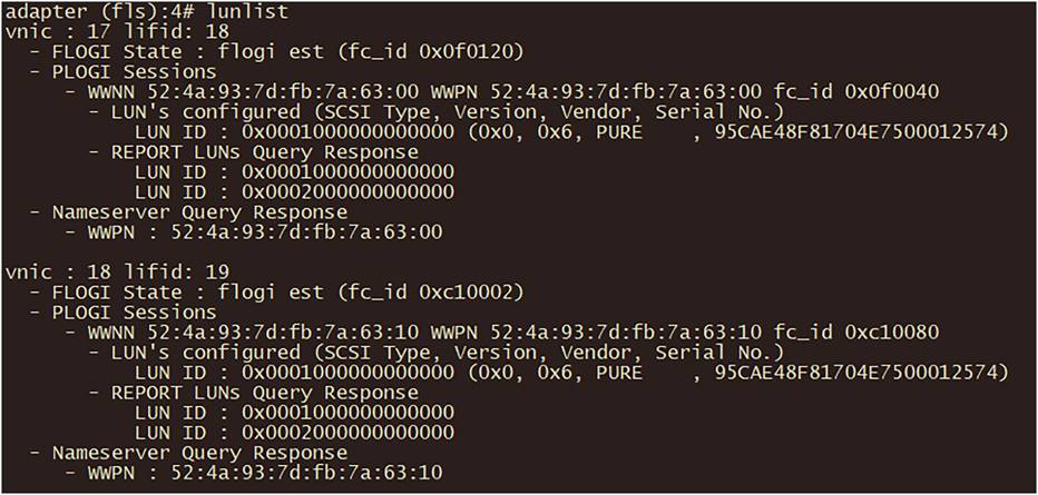
LUNLIST command output.
If the result is different than expected and the FC connection is not working, check the following:
● It the Target correctly configured in the Boot Policy?
● Is zoning correctly configured on the MDS switch?
● Is the LUN ID correct?
FC congestion
When there is oversubscription in the UCS domain, FC congestion can happen.
To verify if there is FC congestion on the fabric interconnect, use the following logging command when in the nxos CLI mode of the fabric interconnect: show logging onboard fc-datarate.
The default for this feature is ON, and the default thresholds are 80/70. Only Cisco Technical Assistance Center (Cisco TAC) can change these values if needed for debugging on the system.
The solution to prevent FC congestion is to add more FC uplink cables from the fabric interconnect to the SAN network or SAN storage.
After configuring Fibre Channel, you can boot from SAN (FC) when following these steps:
1. Create a Boot Order Policy.
2. Add Boot Device: SAN Boot.
3. Give it a Device Name.
4. The LUN should have the same value the LUN as configured on the SAN Target.
5. The Interface Name is the FC interface as configured in the SAN policy.
a. To verify the Interface Name, check at the server profile the vNICs/vHBAs tab, and there you will find displayed the vHBAs’ names.
6. The Target WWPN is the WWPN of the SAN device.

Boot policy for boot from SAN.
7. Apply this to the server policy.
The fabric interconnect has the capability to do limited zoning when it is in FC switch mode. This configuration combines direct attached storage with local zoning.
Instead of having a SAN network, it is possible to directly attach a SAN target with Fibre Channel to the fabric interconnect. The fabric interconnect manages the zoning; external zoning is not possible.
To configure Direct Attached Storage, change the domain profile. This will result in different policies settings in the server profile, and the server profile should with different policies.
Note: Do not configure VSANs in the range from 3040 to 4078 when using FC switch mode.
Let’s start with the domain profile.
Domain profile
For DAS, the VSAN policy is the same as when configuring normal FC; however, the switch control policy is different.
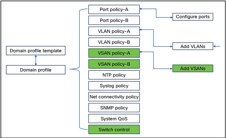
Domain policies that have to be changed for direct attached storage.
1. Create UCS Domain Profile and configure the policies:
● VSAN Configuration
● FC Switch Mode
● Storage Ports
2. Configure the VSAN Configuration and set the VSAN Scope to Storage.
This will have the fabric interconnect take care of the zoning.
If the setting is Storage & Uplink, the zoning should be configured on the external MDS switches.
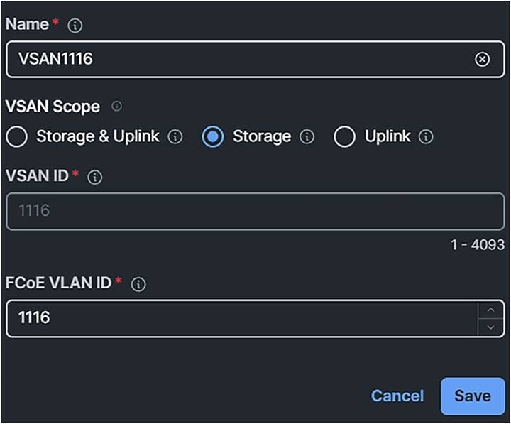
Domain profile VSAN scope.
3. Create two different VSAN configurations, one for SAN-A, the other for SAN-B.
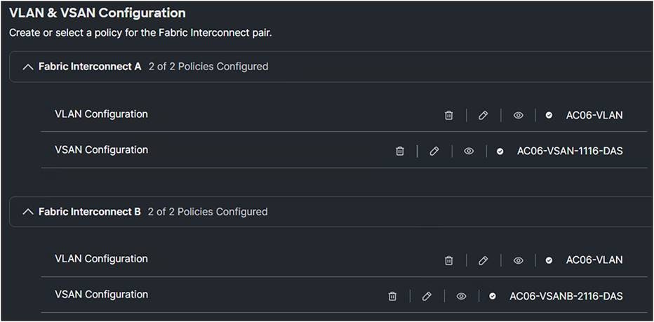
Domain policy VLAN & VSAN configuration.
4. Change the Ports Configuration.
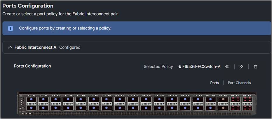
Domain profile port configuration.
5. Configure the ports that connect directly to the SAN target as FC Storage ports.
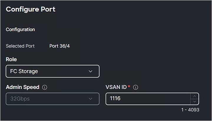
Domain profile single port configuration.
6. Configure another Port Policy for Fabric Interconnect B with a different VSAN ID.
This will have the SAN-A and SAN-B configurations.
7. Create a switch control policy with FC Switch Mode.
FC Switch Mode is a traditional Fibre Channel switching mode and allows the fabric interconnect to connect directly to a storage device.
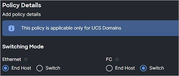
Domain profile switching mode.
8. Enable the fabric port-channel vHBA reset when an FC port channel is present.
The port -channel operations involve addition or removal of a member link between a fabric interconnect and an I/O Module (IOM). Such operations may result in a long I/O pause or connection drop from virtual machines to its targets and require vHBA reset support.
With the fabric port-channel vHBA reset set to enabled, when the Cisco UCS IOM port-channel membership changes, the fabric interconnect sends a registered state change notification (RSCN) packet to each vHBA configured through that Cisco UCS IOM. The RSCN enables the Virtual Interface Card (VIC) or VIC driver to reset the fabric port-channel vHBA and restore connectivity.
By default, the fabric port-channel vHBA reset is set to disabled.
When disabled (default), the vHBA reset kicks in only when all the members of a fabric port-channel are down.
Note: Cisco Intersight Infrastructure firmware version 4.1(3e) and above support this feature.
ESX NFNIC driver version 5.0.0.37 and later or 4.0.0.87 and later process this RSCN.
Linux FNIC driver version 2.0.0.85 and later process this RSCN.

Port-challen vHBA reset.
9. Click Save, and Switch Control should display a policy in the domain profile.

Domain profile policies.
10. Deploy the domain profile.
Note: When switching, make sure to set the Switch Control back to FC end-host mode. Although the default mode is FC end-host mode, after a change, if it is not explicitly acted on, it will stay in the last mode.
From FC End Host to FC Switch Mode is without the need of a fabric interconnect reboot. Switching from FC Switch Mode back to FC End Host mode, will reboot the fabric interconnects automatically without warning.
Server profile for DAS
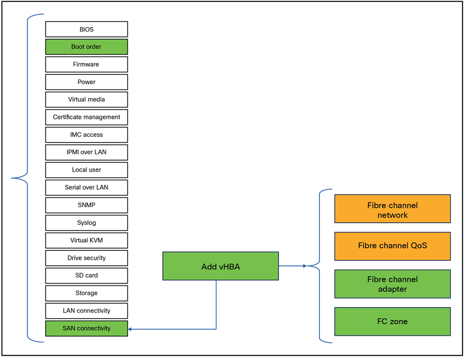
Server policies that have to be changed for direct attached storage.
1. Create an optional Boot Order Policy:
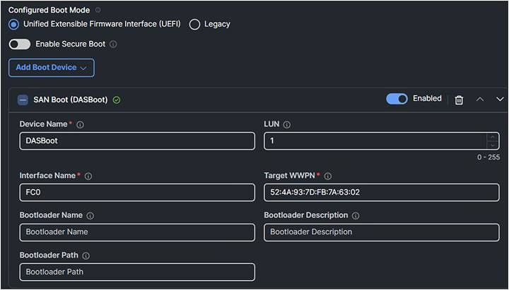
Boot policy.
2. Create a SAN Connectivity Policy.
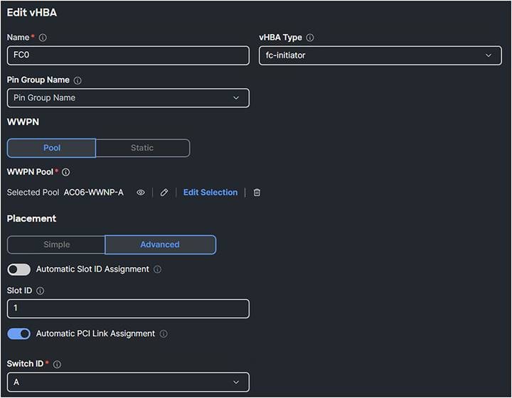
San connectivity policy
3. Configure the FC Zone Policy.

Fibre Channel Network Policy

FC Zone Policy
In the SAN connectivity policy, the FC Target Zoning Type figures out how the Fibre Channel zoning is configured between the initiators and the SAN targets. There are three types of FC Target Zoning:
i. None:
◦ Description: There is no zoning.
◦ When to use: Use this choice when there is no need to rely on upstream FC switches for zoning.
ii. Single Initiator Single Target:
◦ Description: Each vHBA is zoned to a single SAN target (storage port). Each zone has two members.
◦ When to use: Use this choice when there is a simple setup with one storage port connected to one fabric. This is ideal for environments where each server needs to communicate with a specific storage port without sharing it with other servers. Configure this type of zoning unless the number of expected zones exceeds the maximum supported (8000 zones, 500 zone sets).
iii. Single Initiator Multiple Targets:
◦ Description: Each vHBA is zoned to multiple SAN targets (storage ports).
◦ When to use: Use this choice when there is a more complex setup with multiple storage ports connected to one fabric. This is suitable for environments where a server needs to communicate with multiple storage ports, providing redundancy and load balancing. Configure this type of zoning if the expectation is the number of zones will reach or exceed the maximum supported (8000 zones, 500 zone sets).
4. Add a target and configure it with the right switch ID (SAN-A or SAN-B) and the corresponding VSAN ID of that SAN.
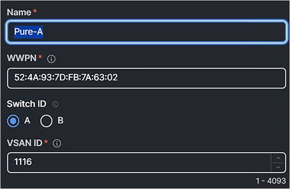
FC target zoning.
Figure 88 displays the result with the policies attached.
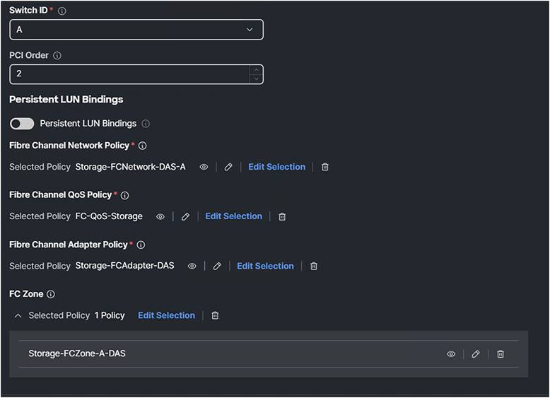
SAN connectivity profile with attached policies.
And do it also for the other interface, which is the SAN-B.
Because this is a Direct Attached Storage configuration, it is best practice to configure two interfaces: one for SAN-A and the other for SAN-B.
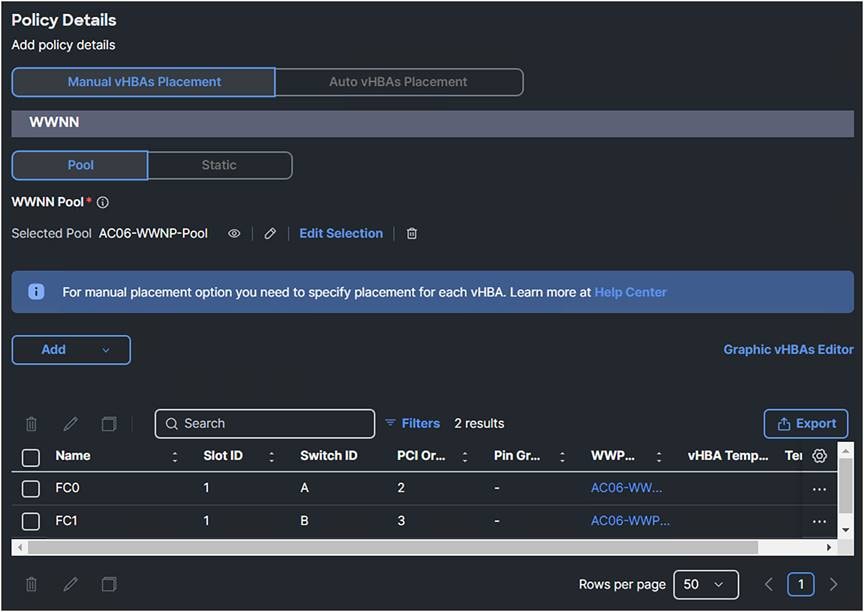
SAN connectivity policy.
Verify Direct Attached Storage
To verify if the configuration is correct, the same commands on the fabric interconnect can be used. See section “Troubleshooting FC on Cisco UCS.”
Here is an example screenshot when starting the server with a legacy boot mode configured.

Legacy boot screenshot of boot from SAN.
The UEFI boot mode is displayed as in Figure 91.
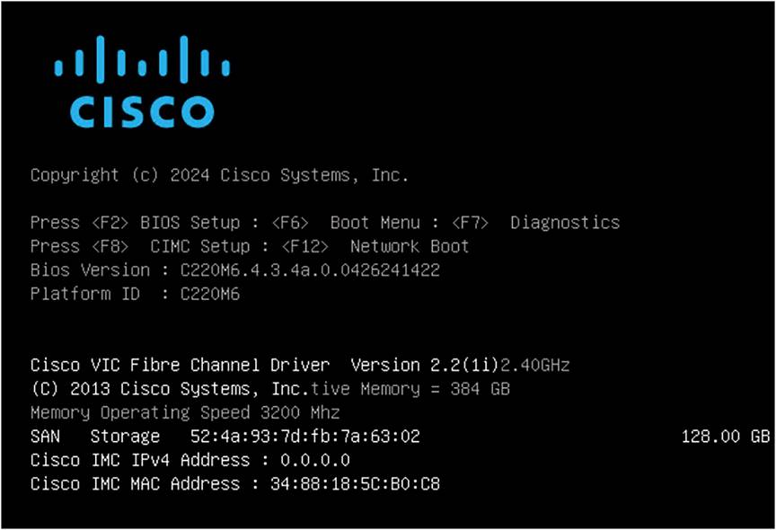
UEFI boot screenshot of boot from SAN.
SAN Storage with the Target WWN and the size of the LUN are displayed just above the Cisco IMC IPv4 Address.
iSCSI is a storage protocol where SCSI commands go over the IP network. No configuration is needed in Intersight to configure the iSCSI Storage Target and Initiator.
If iSCSI boot is needed, it must be configured in Intersight.
Figure 92 shows the policies that need to be configured for a iSCSI boot.
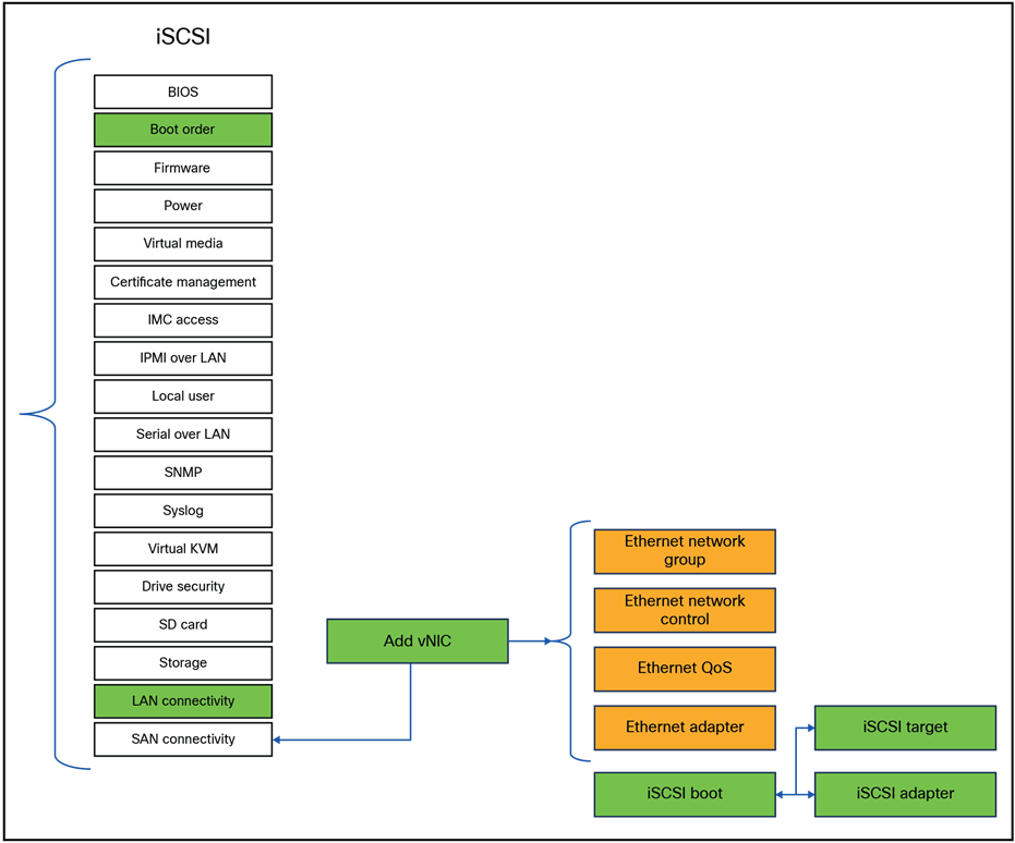
Server policies that have to be changed for iSCSI boot.
Configuring iSCSI boot in UEFI mode and in legacy mode are the same, except for configured boot mode.
The views during boot and the output of troubleshooting are a bit different. Both views will be shown in this chapter.
Note: iSCSI boot policy is not available for servers in standalone mode. Configure the related iSCSI details for a standalone server using the Cisco IMC UI.
Configure the boot policy with a new vNIC name for iSCSI boot. The new vNIC will be added in the LAN Policy.
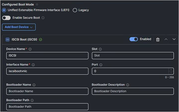
Boot policy.
Edit or configure the LAN connectivity policy.
1. Configure static with the IQNs. (You can select a pool for the IQN pool, but using a static IQN is best practice.)
2. Add a new vNIC for boot.
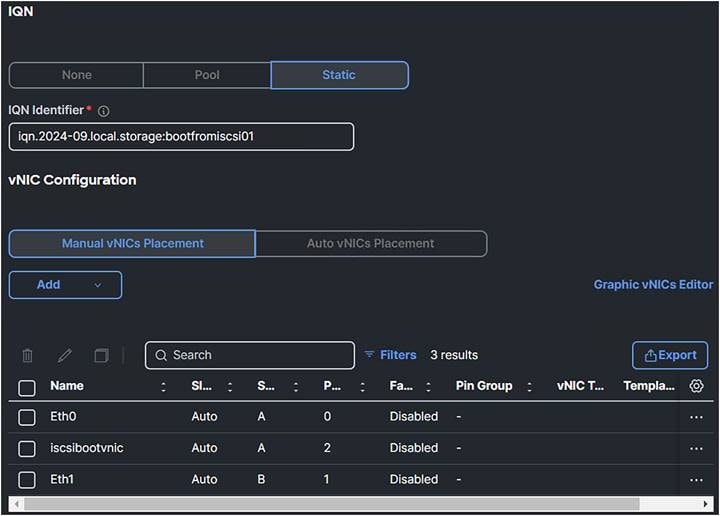
LAN connectivity policy.
3. The PCI order is the next available number in the sequence. In this case it is two. The Mac Pool can be an existing one if there are enough MACs.
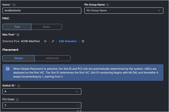
vNIC configuration.
4. Configure a new Ethernet Network Group with only iSCSI VLAN configured.
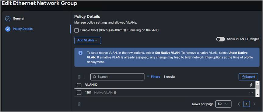
Ethernet network group policy.
5. You can use the default values for Ethernet Network Control, Ethernet QoS, and Ethernet Adapter. Best practice is to have an MTU of 9000.
6. Create a new iSCSI Boot Policy.
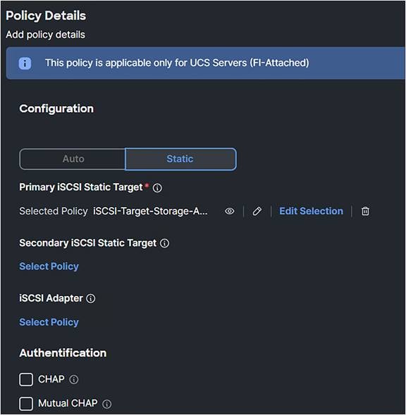
iSCSI boot policy.
7. Configure the iSCSI Static Target.
Use the Target Name of the iSCSI target and fill in the IP Address of the target. The default iSCSI port is 3260.

iSCSI boot policy with static target.
8. The IP Pool is a pool that has an IP address in the iSCSI VLAN range.

iSCSI boot policy ip pool selection.
Apply the server profile with these changes.
When UEFI is configured, during the server boot the following is displayed:
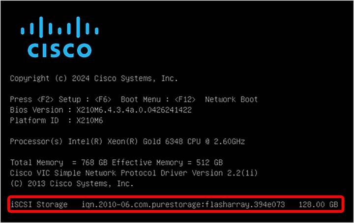
UEFI boot mode iSCSI verification.
In legacy mode, the following is shown:

Legacy boot mode iSCSI verification.
In the UEFI shell, type the command: map-b.
You will get a result as in Figure 102.

UEFI shell.
Connect, using SSH, to the fabric interconnect and then connect to the server adapter:
Example: connect adapter 1/4/1
Type: attach-mcp
The command iscsi_show_eficfg will have an output as in Figure 103 when UEFI is configured.
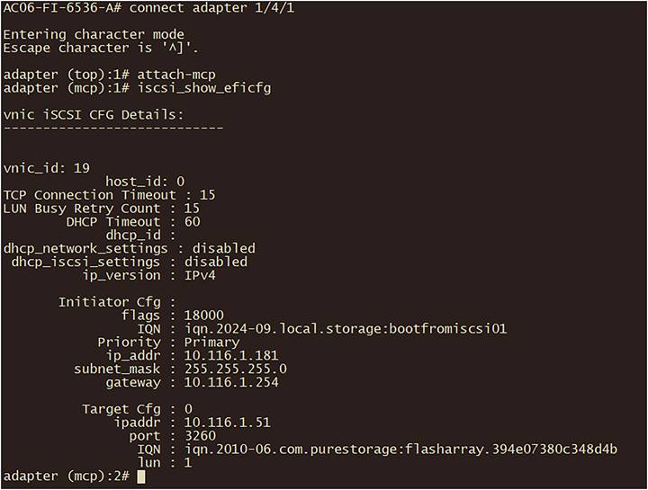
iSCSI verification in fabric interconnect.
The iscsi_get_config command is for iSCSI Boot in legacy mode:
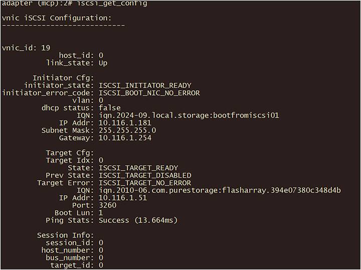
Output of iscsi_get_config command in fabric interconnect.
The command iscsi_show_ibft gives an output as in Figure 105:
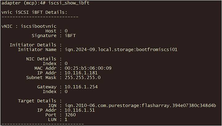
Output of iscsi_show_ibft in fabric interconnect.
NVMe over Fabric provides NVMe commands and messages over a fabric.
The three main NVMe over Fabrics are covered in this document.
Cisco UCS B-Series, C-Series, and X-Series servers support NVMe over Fabric.
Before starting to configure a server for NVMe over Fabric, please have a look at the Cisco UCS NVMeoF Support Matrix for 3rd Party Storage Vendors; https://www.cisco.com/c/en/us/td/docs/unified_computing/ucs/release/notes/b_release-notes-ucsm-4_3.html#ucs-nvmeof-support-matrix-for-3rd-party-storage-vendors.
Note:
● Boot from NVMe over Fabric is not possible at this time.
● Connecting hosts and target ports to the same switch may lower latency and lessen congestion.
● To avoid congestion, do not mix port speeds.
Configuring NVMe over FC is not much different compared to configuring FC.
Adding extra vHBAs for the purpose of having NVMe over FC has a different vHBA type. The rest of the configuration can be the same as a FC configuration.
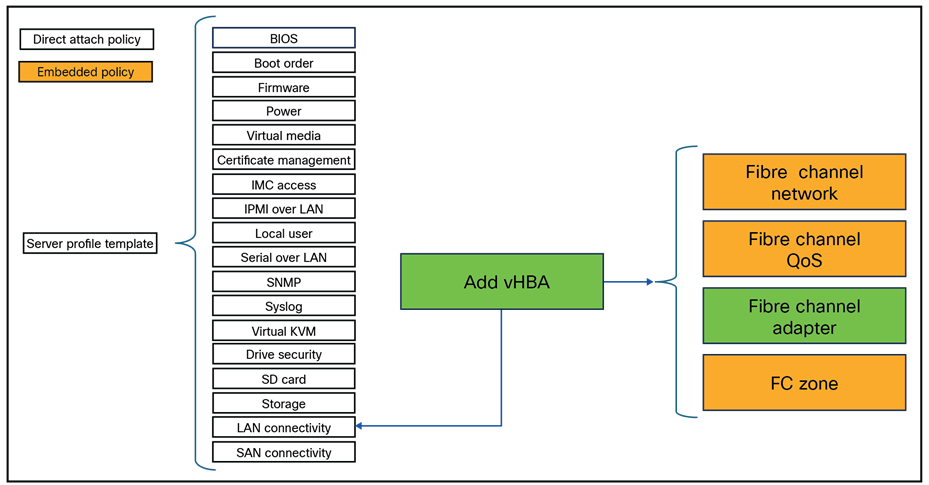
Server profile changes for NVMe over Fibre Channel.
1. Add a vHBA to the server profile. The vHBA Type should be fc-nvme-initiator.

SAN connectivity policy.
2. Create a new Fibre Channel adapter policy and click Select Cisco Provided Configuration.
3. Select FCNVMeInitiator.
This will have default values that are the best for NVMe over FC.
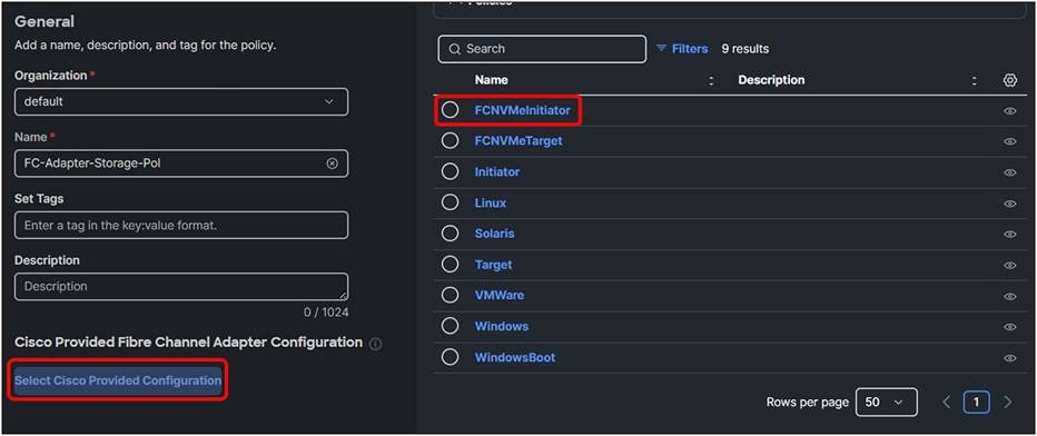
Fibre Channel adapter policy.
4. Change the SCSI I/O Queues to 16 if the value isn’t set in the Fiber Channel adapter policy.

Fibre Channel adapter policy with SCSI I/O value of 16.
5. The MDS switches need to have the correct zoning; configure the FC Target to accept the initiator requests.
6. On the operating system, install the fnic drivers.
For more information about these steps, go to section OS driver installation.
To configure NVMe over TCP, the only configurations needed are on the initiator and target sides.
Here is a list of network best practices:
● Enable Jumbo Frames end-to-end.
● Verify TCP MSS (maximum segment size).
● Use Multipathing IO (MPIO) to improve load balancing.
● Quality of Service (QoS):
◦ Classification: identify and mark traffic using Ethernet CoS and IP DSCP.
◦ Queuing: assign traffic to right queues (for example, no-drop or normal queue).
◦ Queue management: manage queues using techniques such as Weighted Random Early Detection (WRED or Active Format Description (AFD).
◦ Scheduling: schedule packets from multiple queues using methods such as Deficit Weighted Round-Robin (DWRR).
● Traffic prioritization:
◦ Avoid using the QoS priority command for storage traffic because it may not be apt for all application requirements.
◦ Ensure that storage traffic can consume 100% capacity when other classes don’t have traffic, but the NVMe over TCP is limited to guaranteed bandwidth when other classes have traffic.
● Avoid policing or shaping:
◦ Both policing and shaping can lead to mediocre performance for storage traffic. The aim should be to have enough network capacity to avoid the need for these actions.
● Dedicated storage network:
◦ Prefer dedicated networks for storage traffic to avoid traffic contention, simplify troubleshooting, and manage changes more easily.
● Load balancing:
◦ NVMe over TCP creates one TCP connection per I/O submission and completion-queue pair, leading to better load balancing on network links.
Cisco Intersight Managed Mode (IMM) provides Ethernet Adapter policies that can be used to optimize network traffic into multiple receive queues to enable the use of multiple CPU cores to service the traffic in the queues and achieve a higher network throughput.
These adapter policies allow the number of transmit (TX) and receive (RX) queues and the queue ring size (buffer size) to be adjusted, and features such as Receive Side Scaling (RSS) to be enabled.
RSS allows multiple RX queues to be assigned each to a different CPU core, allowing parallel processing of incoming Ethernet traffic.
VMware ESXi 8.0 supports RSS, a single TX queue, and up to 16 RX queues.
The best practice is to have an RX Queue of 16.
The fifth-generation Cisco VICs support a TX and RX ring size up to 16,384.
Increasing the ring size can increase the latency, but on higher speed (100GbE) interfaces the higher speeds mean less time for the data to sit in the buffers, thereby minimizing the latency impact.
Here is an example of a configuration of Red Hat with a NVMe over TCP initiator: https://docs.redhat.com/en/documentation/red_hat_enterprise_linux/9/html/managing_storage_devices/configuring-nvme-over-fabrics-using-nvme-tcp_managing-storage-devices#connecting-the-nvme-tcp-host-to-the-nvme-tcp-controller_configuring-nvme-over-fabrics-using-nvme-tcp.
Verify the adapter settings in the fabric interconnect.
1. Connect to the fabric interconnect through SSH.
2. Connect to the right adapter for the server. Use the command connect adapter x/y/z where x is the chassis number, y is the slot number, and z is the adapter number.
3. After login, type the command attach-mcp.

vnicl command in fabric interconnect.
4. Run the command vnicl.
Search for the correct vNIC to verify its details. In this case, the information for Eth0 is displayed.
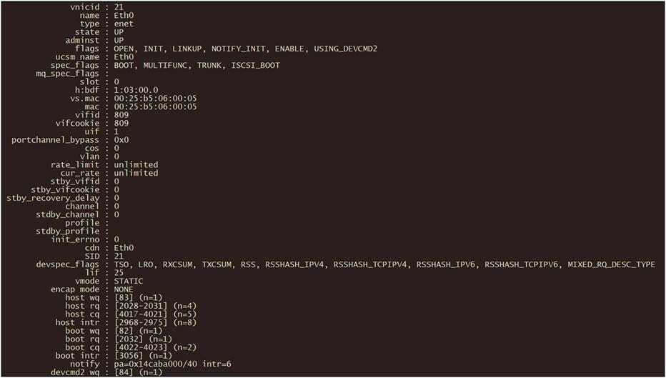
Output of vnicl command in fabric interconnect.
The output displays the information about the wq (write queue) and rq (read queue).
NVMe over RoCEv2 is a protocol with low latency, and it uses Ethernet as a transport protocol.
The following policies will be changed in the server profile.
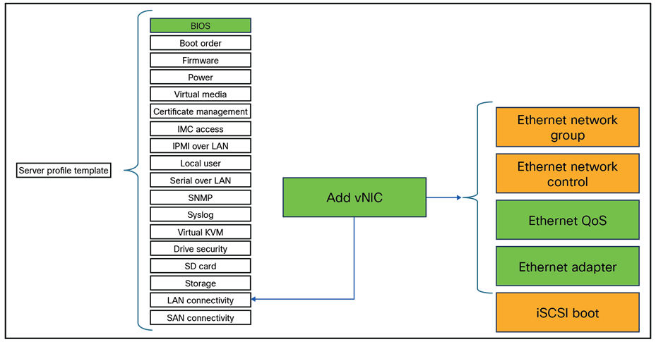
Server profile policies change for NVMe over RoCE.
General guidelines and limitations:
● Non-Volatile Memory Express (NVMe) over RDMA with RoCE v2 is currently supported only with Cisco UCS VIC 15000 Series adapters.
● When creating RoCE v2 interfaces, use (as recommended by Cisco) queue pairs, memory regions, resource groups, and class-of-service settings.
● RoCE v2 supports a maximum of two RoCE v2–enabled interfaces per adapter.
● Layer-3 routing is not supported.
● Saving a crash dump to an NVMeoF namespace during a system crash is not supported.
● NVMeoF cannot be used with usNIC, VxLAN, VMQ, VMMQ, NVGRE, GENEVE Offload, ENS, and DPDK features.
● Cisco Intersight does not support fabric failover for vNICs that have RoCE v2 enabled.
● The Quality of Service (QoS) no-drop class configuration must be properly configured on upstream switches such as Cisco Nexus 9000 Series Switches. QoS configurations will vary between different upstream switches.
● During a failover or failback event Spanning Tree Protocol (STP) can result in a temporary loss of network connectivity. To prevent this connectivity issue, disable STP on uplink switches.
● NVMe over RoCE does not support boot from SAN at this moment of writing.
● Cisco VIC does not support Explicit Congestion Notification (ECN).
● When creating RoCEv2 interfaces, use the Intersight-provided Linux-NVMe-RoCE adapter policy. (Do not use the default Linux adapter policy with RoCEv2; RoCEv2 interfaces will not be created in the OS.)
● In the Ethernet adapter policy, do not change the values of queue pairs, memory regions, resource groups, and priority settings other than to the default values provided by Cisco. NVMe over Fabric functionality may not be guaranteed with different settings for queue pairs, memory regions, resource groups, and priority.
● RoCEv2 does not support bonding.
● Linux RoCEv2 interface supports only MSI-x interrupt mode. Cisco recommends avoiding changing interrupt mode when the interface is configured with RoCEv2 properties.
● The smallest interrupt-count for using RoCEv2 with Linux is 8.
The best practices for configuring NVMe over RoCEv2 in Cisco Intersight are:
● Create VLANs for NVMe over RoCE.
● Enable Platinum QoS CoS5 with Jumbo MTU.
Two adapter policies are best practice, because there are diverse types of traffics, each with different priories.
One traffic is the public traffic for managing servers, and the other traffic is the storage traffic using NVMe over RoCE, which needs to be classified as high priority traffic. For these reasons, two different adapter policies are created, one adapter policy for public traffic and a second adapter policy for storage RoCE traffic, as explained in the following sections.
Make sure the Domain Profile has a QoS set with Platinum enabled and an MTU of 9216.
1. Create a System QoS policy with the following settings:
● Priority: Platinum
● Allow Packet Drops: Unchecked
● MTU: 9216
2. Apply this policy to the domain profile.

Domain profile QoS settings.
3. Add to the server profile the following BIOS policy.
Create a BIOS policy that has the following options enabled:
● For Intel®-based servers, Intel VT for Directed IO under the Intel Directed IO tab.
● For AMD-based servers, SVM Mode under the Processor tab.
● Enable IOMMU under the Memory tab.
Intel:
1. Enable Intel VT for Directed IO.

BIOS profile setting for Intel CPUs.
AMD:
1. Enable SVM Mode under Processor.

BIOS profile settings for AMD CPUs.
Both Intel and AMD CPUs should have Input / Output Memory Management Unit (IOMMU) enabled.
1. Enable IOMMU under Memory.
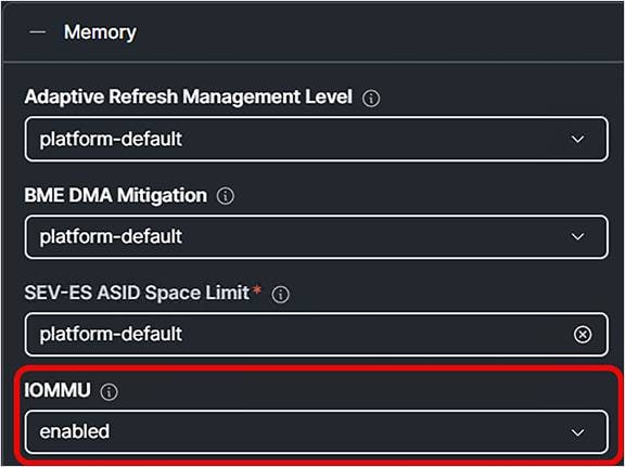
Enable Input/Output memory management unit in BIOS policy.
1. Create a LAN connectivity policy with the following parameters:
● Add a VNIC.
● Fill in a Name.
● Fill in the Switch ID.
● Do not enable Failover because RoCE will not work if Failover is enabled.
● Create an Ethernet Network Group policy, and fill in the RoCE VLAN ID.
● Create an Ethernet Network Control policy and leave the defaults.
● Create an Ethernet QoS policy and set the MTU Bytes to 9000.
● The Priority should be set to Platinum.

Ethernet QoS policy.
2. Create an Ethernet Adapter policy and select Cisco Provided Configuration.
Choose Linux-NVMe-RoCE because this predefined configuration has the best settings for NVMe over RoCE.
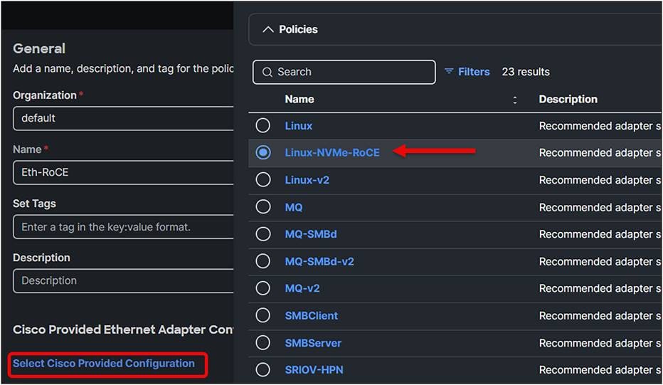
Ethernet adapter policy.
Verify the following values:
● Set Queue Pairs to 1024.
● Set Memory Regions to 131072.
● Set Resource Groups to 8.
● Select Version 2.
● Set Class of Service to 5.
● Set Interrupts to 256.
● Select Interrupt mode MSI-x.
● Set Interrupt Timer to 125.
● Select Interrupt Coalescing Type Min.
● Set Receive Queue Count to 1.
● Set Receiving Ring Size to 512.
● Set Transmit Queue Count to 1.
● Set Transmit Ring Size to 256.
● Set Completion Queue Count to 2.
● Set Completion Ring Size to 1.
● Set Uplink Failback Timeout to 5.
After creating the Ethernet Adapter policy, the LAN connectivity policy should look like the display in Figure 119.
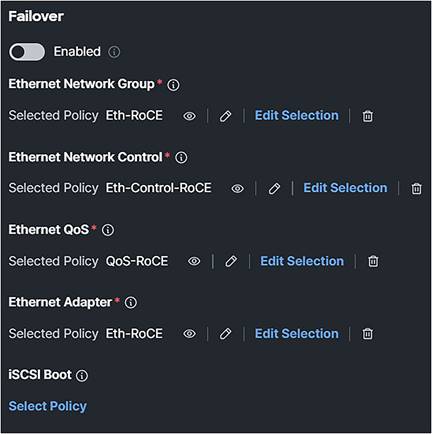
LAN connectivity policy.
An example of a configuration of NVMe over RoCE for Red Hat: https://docs.redhat.com/en/documentation/red_hat_enterprise_linux/9/html/managing_storage_devices/configuring-nvme-over-fabrics-using-nvme-rdma_managing-storage-devices.
Install enic and enic_rdma drivers on the operating system.
The next section covers installing the OS driver.
In this document, there are references to installing the enic, enic_rdma, and fnic drivers for the Operating System (OS). This section describes how to install these OS drivers.
Note:
● The enic RDMA driver works in conjunction with the enic driver.
Load the enic_rdma before the enic driver while configuring NVMe over Fabric.
● When configuring RoCEv2 interfaces, use both the enic and enic_rdma binary drivers downloaded from Cisco.com, and install a matched set of enic and enic_rdma drivers. Attempting to use the binary enic_rdma driver downloaded from Cisco.com with an inbox enic driver will not work.
First find the right driver for the desired configuration at the Cisco UCS HCL Tool: https://ucshcltool.cloudapps.cisco.com/public/
1. Search, using the Operating Systems option:
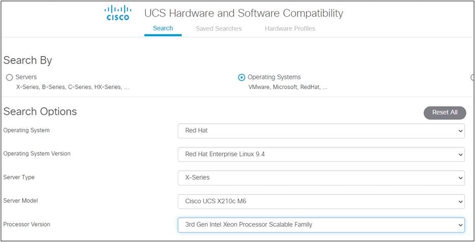
Cisco UCS HCL tool.
2. Use the filters to narrow the selection.
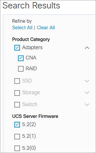
Filter the search results.
Here are the CNAs with the driver versions.
3. Download the drivers, using the Drivers ISO link.
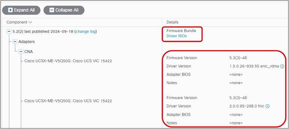
Select the right drivers.
To install the driver to the operating system, mount the ISO and install the required driver.
UCSM RoCEv2 Configurations Guide (4.2)
Configure Direct Attached Storage in Intersight Managed Mode Domain
Configure Boot from Local Storage in Intersight Manage Mode (IMM)
Intersight Self Encrypting Drives Configuration
Configure SAN Port-Channel between UCS IMM and MDS
Configure Direct Attached Storage in Intersight Managed Mode Domain
Configure Boot from SAN in IMM
Cisco UCS VIC 15000 Series Best Practices in Ethernet Fabric White Paper
Cisco Intersight Configuration Guide for RDMA over Converged Ethernet (RoCE) Version 2
Troubleshooting Boot From SAN Installation