Enabling Cisco HyperFlex Systems to Coexist with Fibre Channel Shared Storage
Available Languages
Bias-Free Language
The documentation set for this product strives to use bias-free language. For the purposes of this documentation set, bias-free is defined as language that does not imply discrimination based on age, disability, gender, racial identity, ethnic identity, sexual orientation, socioeconomic status, and intersectionality. Exceptions may be present in the documentation due to language that is hardcoded in the user interfaces of the product software, language used based on RFP documentation, or language that is used by a referenced third-party product. Learn more about how Cisco is using Inclusive Language.
Author: Hui Chen
Last Updated: November 7, 2023
Note: This document contains material and data with multiple dependencies. The information may be updated as and when necessary and is subject to change without notice.
Traditional data center infrastructure is often built using separate physical components for computing, storage, and networking resources. This practice generates silos within which only a single technology operates, along with its correlated software tools and support staff. Siloed technologies create complexity and make the various components more difficult to deploy and manage, with weeks or months sometimes required to bring all these resources into production. Cisco® converged infrastructure provides strong solutions that break down the silos, integrating the Cisco Unified Computing System™ (Cisco UCS) platform, Cisco data center switching products, and third-party Fibre Channel storage arrays into a virtualized computing system that can be rapidly deployed and easily managed. The converged infrastructure solutions have been developed to operate in predefined, tested, and validated designs. These solutions have been extremely successful and have become leaders in the market. However, recent significant changes in the fast-evolving industry have given rise to the hyperconverged system, which combines computing resources and software-defined storage (SDS) to deliver a simplified solution for mainstream workloads.
A proven industry-leading hyperconverged solution, the Cisco HyperFlex™ system is an optimized choice for many applications in a virtualized environment. The Cisco HyperFlex system provides an all-purpose virtualized server platform, with hypervisor hosts, network connectivity, and virtual server storage across a set of Cisco HyperFlex HX-Series x86 rack-mount servers. The platform combines the converged computing and networking capabilities provided by Cisco UCS with next-generation hyperconverged storage software to uniquely provide the computing resources, network connectivity, storage, and hypervisor platform needed to run an entire virtual environment, all contained in a single uniform system.
Cisco HyperFlex systems deliver many enterprise-class features, such as:
● A fully distributed log-structured file system that supports thin provisioning
● High performance and low latency from the flash-friendly architecture
● In-line data optimization with deduplication and compression
● Fast and space-efficient clones through metadata operations
● The flexibility to scale out computing and storage resources separately
● Data-at-rest encryption using hardware-based self-encrypting disks (SEDs)
● Non-Volatile Memory Express (NVMe)–based solid-state disk (SSD) support
● Native replication of virtual machine snapshots
● Cloud-based smart management
Even though the Cisco HyperFlex platform is fast to deploy, simple to manage, easy to scale, and ready to provide a unified pool of resources to power many applications, many customers may still have converged infrastructure solutions deployed for some use cases. For example, customers may deploy some mission-critical virtual machines backed by a Fibre Channel–based SAN storage system while keeping other applications on a Cisco HyperFlex distributed file system. In a common scenario in the data center, converged infrastructure and hyperconverged infrastructure (HCI) coexist, but the storage resources need to be shared.
This document presents a validated solution that demonstrates the coexistence of Cisco HyperFlex systems along with Fibre Channel shared storage arrays in a scenario in which the Cisco HyperFlex system requires access to the storage volumes or logical unit numbers (LUNs) in the Fibre Channel storage array. It presents detailed procedures for enabling Fibre Channel connectivity in the Cisco HyperFlex cluster and describes how to configure the Cisco MDS Fibre Channel switches, share the Fibre Channel data store with the Cisco HyperFlex cluster, and expand the Cisco HyperFlex cluster with a SAN-boot Cisco UCS server.
When you build or expand the IT infrastructure in your data center, the storage solution is always an essential and critical component. The choice of storage architecture is important because the efficiency of the infrastructure affects the efficiency of the application and the speed of data collection and processing, storage performance, and resource management. Deciding where to save the data, where to pull the data from, and which solution provides the best storage efficiency and performance will seldom be easy choices for customers.
In the past decades, SANs have played an important role in the data center. A SAN is a specialized high-speed network that connects computer systems, or hosts, to high-performance storage systems. Fibre Channel is the most frequently used storage protocol on hosts for connecting to the shared storage systems in a SAN environment. In the most commonly used form, the protocol packages Small Computer System Interface (SCSI) commands into Fibre Channel frames that are transported across a dedicated switched fiber-optic network. To connect to the Fibre Channel SAN, the hosts must have Fibre Channel host bus adapters (HBAs), and the storage systems must have Fibre Channel controllers. The hosts and the storage systems communicate with each other by connecting through the Fibre Channel switches. Traditionally, the hosts in the data center have two types of adapters: network interface cards (NICs) for LAN traffic and Fibre Channel HBAs for SAN traffic. Cisco Converged Infrastructure successfully consolidates these two networks into one single converged network at the host side. With the innovative Cisco Unified Fabric technology, Cisco UCS servers converge LAN and SAN traffic with one adapter by connecting a Cisco virtual interface card (VIC) to the converged Cisco UCS fabric interconnect switch pair, and then connecting to the upstream LAN switches and the Fibre channel SAN switches.
Given the exponential rate of data growth in the world today, the capability to scale traditional storage infrastructure in a cost-effective way is becoming increasingly challenging. Storage technology over the years has experienced incremental advancements that have brought more choices to the data center. SDS virtualization is an excellent solution for mitigating these challenges. SDS technology allows the sharing and easy expansion of underlying hardware resources for use by multiple workloads. This approach leads to greater utilization of resources while providing the necessary fault tolerance in a software-defined manner. The software-defined storage market has experienced strong growth driven by the growth of new applications such as big data and analytics, artificial intelligence, machine learning, and the internet of things (IOT). The evolution of new storage technologies such as NVMe, NVMe over Fabrics, and storage-class memory has also broadened the scope of the existing workloads that SDS will be able to handle at scale.
Hyperconvergence is an evolving technology that builds on the many benefits of SDS and virtualization. A proven industry-leading hyperconverged platform, Cisco HyperFlex systems are an optimized choice for many applications in a virtual environment. Cisco HyperFlex systems let you unlock the full potential of hyperconvergence and adapt IT to the needs of your workloads. They can be deployed quickly and are highly flexible and efficient, reducing risk for the customer. With Cisco HyperFlex systems, customers have many choices and the flexibility to support different types of workloads without compromising their performance requirements.
The coexistence of classic SAN storage systems and distributed HCI in the same IT environment is common in today’s data center. A solid storage architecture should always strive for flexibility to allow resources to be shared and consumed where needed, to optimize the use of various tiers of storage according to their performance profile, and to form an efficient storage design that allows local data to be handled quickly and stored safely on remote devices. A good storage architecture should also aim to protect existing IT investments: not only the investment in the local storage systems, but also the investment in the interconnect infrastructure between data centers for disaster recovery. With Cisco HyperFlex systems, you can easily connect outside resources and data to your new systems, allowing you to move data and applications from existing environments to Cisco HyperFlex systems. This capability also supports virtual machine mobility, allowing you to move virtual machines through VMware Storage vMotion without having to take applications offline. You also can simply and quickly back up and archive your data to traditional Fibre Channel–based storage systems by easily adding Fibre Channel virtual HBAs (vHBAs; not physical HBAs) to Cisco HyperFlex hosts. As a result, you can shift these resources across HCI, converged infrastructure, and traditional infrastructure. Computing-only nodes can be used as part of a Cisco HyperFlex cluster, and then according to seasonal or daily application demands, they can be shifted back to support traditional infrastructure, providing true cloud-like agility across your data center.
The goal of this document is to establish a validated solution for an IT infrastructure in which storage resources can be seamlessly shared between Cisco HyperFlex systems and the Fibre Channel storage arrays in the SAN. Figure 1 shows this solution.
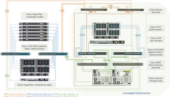
High-level solution overview
The Cisco HyperFlex solution delivers a new generation of flexible, scalable, enterprise-class hyperconverged solutions. It is designed with an end-to-end software-defined infrastructure that combines software-defined computing in the form of Cisco UCS servers, software-defined storage with the powerful Cisco HyperFlex HX Data Platform software, and software-defined networking with Cisco Unified Fabric that integrates smoothly with Cisco Application Centric Infrastructure (Cisco ACI™). These technologies together offer a single point of connectivity and management and deliver a validated and adaptable cluster with a unified pool of resources that you can quickly deploy and manage to efficiently power your applications for your business. Customers can benefit from this complete end-to-end hyperconverged solution in various ways: speed of installation, simplicity of deployment, flexibility with a “pay-as-you-grow” model, agility to support any workload, and centralized cloud-based management. With the capability to integrate Cisco UCS servers as computing-only nodes and increase processing capacity with graphic processing unit (GPU)–intensive Cisco UCS servers, you can scale computing and storage resources independently to closely match your application needs.
Designed as an enterprise-ready storage system, the Cisco HyperFlex solution also delivers many storage features, such as:
● Always-on inline data deduplication and compression for greater capacity
● Fast and space-efficient cloning and snapshots
● Highly scalable, enterprise-class hyperconverged storage performance
● Thin provisioning
● Support for hybrid, all-flash, and all-NVMe nodes for different requirements
● Encryption for data at rest
● Native synchronous and asynchronous data replication
● Logical Availability Zones for higher resilience
A Cisco HyperFlex system is composed of the following components:
● One pair of Cisco UCS fabric interconnect switches
● Cisco HyperFlex HX-Series HX220c or HX240c rack-mount servers
● Cisco UCS C-Series Rack Servers and B-Series Blade Servers as computing-only nodes
● Cisco HyperFlex HX Data Platform software
● VMware vSphere ESXi hypervisor
● VMware vCenter Server (supplied by the end user)
A standard Cisco HyperFlex cluster requires a minimum of three HX-Series nodes. Data is replicated across at least two of these nodes, and a third node is required for continuous operation in the event of a single-node failure. The HX-Series nodes combine the CPU and RAM resources for hosting guest virtual machines with a shared pool of physical storage resources. On the HX-Series hybrid nodes, the storage resources originate from a combination of SSDs for the caching layer and hard-disk drives (HDDs) for the capacity layer. On the HX-Series all-flash nodes, resources originate from a combination of SSDs or NVMe storage for the caching layer and SSDs for the capacity layer. HX-Series all-NVMe nodes use NVMe storage for all caching and capacity functions for an even higher level of performance. The physical disks are logically combined as a storage resource pool and provisioned by the HX Data Platform software. The HX Data Platform software is a purpose-built, high-performance, distributed file system with a wide range of enterprise-class data management services. The software simplifies operations and helps ensure data availability with many enterprise-class storage features.
An HX Data Platform controller resides on each node and implements the HX Data Platform distributed file system. The storage controller runs in user space within a virtual machine, intercepting and handling all I/O requests from guest virtual machines. The storage controller virtual machine uses the VMDirectPath I/O feature to provide PCI pass-through control of the physical server’s SAS disk controller, or PCI pass-through control of the NVMe disks where applicable. This approach gives the controller virtual machine full control of all the physical disk resources of each node. The controller integrates the data platform into VMware software through three preinstalled VMware ESXi vSphere Installation Bundles (VIBs): the VMware API for Array Integration (VAAI), a customized IOvisor agent that acts as a stateless Network File System (NFS) proxy, and a customized stHypervisorSvc agent for Cisco HyperFlex data protection and virtual machine replication.
The HX Data Platform controllers handle all read and write requests from the guest virtual machines to the virtual machine disks (VMDKs) stored in the distributed data stores in the cluster. The data platform distributes the data across multiple nodes of the cluster and across multiple capacity disks in each node according to the replication-level policy selected during cluster setup. The replication-level policy is defined by the replication factor (RF) parameter. When RF = 3, a total of three copies of the blocks are written and distributed to separate locations for every I/O write committed to the storage layer; when RF = 2, a total of two copies of the blocks are written and distributed.
The HX Data Platform can be administered through a VMware vSphere web client plug-in or through the HTML5-based native Cisco HyperFlex Connect management tool. Through the centralized point of control for the cluster, administrators can create data stores, monitor the data platform health, and manage resource use. In addition, since HX Data Platform Release 2.6, Cisco HyperFlex systems also can be created and managed remotely from the Cisco Intersight™ cloud-based management platform.
Unified fabric for Cisco UCS and Cisco HyperFlex systems
The Cisco UCS platform provides the foundation for creating Cisco HyperFlex systems by extending Cisco UCS policy-based deployment and management to Cisco HyperFlex clusters. It also extends unified fabric capacities to Cisco HyperFlex clusters. With Cisco Unified Fabric, multiple types of data center traffic can run over a single Data Center Ethernet (DCE) network. Instead of having a variety of HBAs and NICs present in a server, Cisco Unified Fabric uses a single converged network adapter: the Cisco UCS VIC. The VIC adapter can carry LAN and SAN traffic on the same cable. Cisco UCS uses Fibre Channel over Ethernet (FCoE) to carry Fibre Channel and Ethernet traffic on the same physical Ethernet connection between the fabric interconnect and the server. This connection terminates at a converged network adapter on the server, and the unified fabric terminates on the uplink ports of the fabric interconnect. On the core network, the LAN and SAN traffic remains separated.
The Cisco UCS fabric interconnect provides a single point of connectivity and management for an entire Cisco UCS or Cisco HyperFlex system. It supports unified ports that can be configured to carry either 10/25/40/100-Gbps Ethernet or 8/16/32-Gbps Fibre Channel traffic. At the fabric interconnect, the server-facing Ethernet port receives the Ethernet and Fibre Channel traffic. The fabric interconnect, using EtherType to differentiate the frames, separates the two traffic types. Ethernet frames and Fibre Channel frames are switched to their respective uplink interfaces.
The Cisco UCS VIC adapter extends the network fabric directly to both servers and virtual switches so that a single connectivity mechanism can be used to connect both physical and virtual servers. It supports Cisco SingleConnect technology, which provides an easy, intelligent, and efficient way to connect and manage servers. Cisco SingleConnect unifies LAN, SAN, and systems management into one simplified link for rack servers, blade servers, and virtual machines. This technology reduces the number of network adapters, cables, and switches needed and radically simplifies the network, reducing complexity. Cisco UCS VICs provide complete programmability of the Cisco UCS I/O infrastructure, with the number and type of I/O interfaces configurable on demand with a zero-touch model. Cisco UCS VICs can support 256 PCI Express (PCIe) virtual devices, either virtual NICs (vNICs) or vHBAs, with a high rate of I/O operations per second (IOPS), support for lossless Ethernet, and 10/25/40/100-Gbps connection to servers. It incorporates Cisco’s next-generation converged network adapter (CNA) technology and presents Ethernet interfaces and Fibre Channel interfaces to the operating system. At the server, the operating system is not aware of the FCoE encapsulation because it sees standard Fibre Channel HBAs and standard NIC adapters.
Cisco HyperFlex systems are built on top of the Cisco UCS platform with Cisco UCS fabric interconnects and Cisco UCS VIC adapters. Therefore, this solution is the only hyperconverged infrastructure platform in the industry that can easily share external Fibre Channel storage simply through the addition of vHBAs to the hosts, without the need to physically add HBAs. The vHBAs can be added by defining vHBA template policy in a service profile. This vHBA SAN connectivity template defines how a vHBA on a server connects to the SAN.
A SAN is a specialized high-speed network that connects host servers to high-performance storage subsystems. SAN components include HBAs on the servers, switches, cables, storage processors, and storage disk arrays. A SAN fabric requires at least one switch present on the network to help route storage traffic.
The new generation of the Cisco MDS 9000 Series switches, an important component of the Cisco Unified Fabric solution, provides the flexibility to support multiprotocol storage devices in a single network in which a variety of storage protocols, including Fibre Channel, FCoE, NVMe over Fibre Channel, Fibre Channel over IP (FCIP), SCSI over IP (iSCSI), Network Attached Storage (NAS), and IBM Fiber Connection (FICON), can be used. This multiprotocol storage network starts with mature functions of Fibre Channel SANs and extends them transparently to converged Ethernet environments. It delivers enterprise-class features, reliable performance, integrated inline analytics, and comprehensive resiliency for storage sharing. This document describes only the procedure to connect Cisco HyperFlex systems to the shared storage arrays using the Fibre Channel protocol.
When a host wants to read or write to a disk in the Fibre Channel SAN, the following tasks need to be completed:
1. The physical HBA packages the I/O request according to the rules of the Fibre Channel protocol.
2. The request is transmitted to the SAN.
3. Depending on a port the HBA uses to connect to the fabric, one of the SAN switches receives the request.
4. The switch checks the Fibre Channel zoning configuration to see if the traffic initiated from the HBA is allowed to communicate with the storage device (as explained below).
5. The switch routes the request to the appropriate storage device.
6. The storage device sends the response back to the SAN according to the rules of the Fibre Channel protocol.
7. Depending on a port the storage controller uses to connect to the fabric, one of the SAN switches receives the response.
8. The switch routes the response back to the appropriate physical HBA, which sends the request.
In the context of the Fibre Channel protocol, a port is the connection from a device into the SAN. Each device in the SAN, such as a host or a storage device, has one or more ports that connect it to the SAN. A port is identified with either a World Wide Port Name (WWPN) or port address (port ID). The WWPN is a globally unique identifier for a port. The port ID is a unique identifier that serves as the Fibre Channel address for the port. This unique ID enables routing of data through the SAN to that port. The Fibre Channel switches discover the WWPN of a device and assign a port address to the device when the device logs in to the fabric.
When N-Port ID Virtualization (NPIV) is used, a single Fibre Channel HBA port (N-port) can register with the SAN fabric by using several WWPNs. This method allows an N-port to claim multiple fabric addresses, each of which appears as a unique entity. When Cisco UCS fabric interconnect Fibre Channel uplink ports connect to a SAN, the default end-host mode allows the fabric interconnect to act as an end host (N-port) representing all servers (hosts) connected to it through the dynamically pinned vHBAs. The multiple, unique identifiers will be assigned to each individual vHBA. To support the assignment of multiple Fibre Channel addresses for one single port, the N-Port Virtualization (NPV) feature must be enabled on the Cisco MDS switches.
Cisco MDS 9000 Family switches support a virtualization feature called virtual storage area network (VSAN). VSAN provides isolation among devices that are physically connected to the same fabric. In that way, higher security and greater stability in the SAN fabric can be achieved. Only the member devices in the same VSAN can communicate with each other. VSAN operates in much the same way that a traditional network VLAN does, allowing one physical Fibre Channel switch to be logically split into multiple VSANs, each with its own VSAN ID number. The ports on the Fibre Channel switches are assigned membership to a particular VSAN, allowing those endpoints to communicate, while preventing the other ports, which are assigned to other VSANs, from communicating with them.
To restrict server access to storage arrays not allocated to that server, Fibre Channel zoning is used. Most Fibre Channel switches by default implement so called “hard” zoning, in which no Fibre Channel traffic is allowed to pass unless defined in a zone. Zones are created in the Fibre Channel switches, and they define which HBAs can communicate with which storage controllers. Devices can see and communicate only with what is explicitly defined in the zones of which they are a member, and all other devices outside that zone cannot be seen. Multiple zones are grouped together into a zone set and then made active by an administrator. Zoning is similar to an access control list (ACL), which may be found in a networking switch or router. Like ACLs, Fibre Channel zones define which endpoints in the network are allowed to communicate with each other. Zoning is configured for the devices within the same VSAN, and typically zones are created for each group of servers that access a shared group of storage devices. Zone membership on Cisco MDS switches is based mainly on WWPNs or Fibre Channel port IDs, but zoning with a distributed device alias is also supported. To avoid entering an incorrect WWPN during zoning configuration, a user-defined friendly name for a WWPN can be used. These user-friendly names are referred to as device aliases.
LUN masking is a commonly used form of storage access permission management. LUN masking is a process on the storage system itself that makes a LUN or volume available to some hosts and unavailable to other hosts. After the necessary Fibre Channel zones have been created and activated, the HBAs will be able to communicate with the storage arrays. At that point, storage array administrators can use the storage system management tools to verify that the HBAs are in fact contacting the storage system, and then specify which of the LUNs or volumes are accessible to that particular host. Most storage systems by default present no LUNs or volumes to any hosts without explicit definition. This masking operation hides the LUNs and volumes that a host does not need to see, but allows the needed LUNs or volumes to be scanned and mounted and then send and receive I/O traffic. Until all the proper settings are made for VSAN membership, Fibre Channel zoning, and LUN masking, the hosts will not be able to see or communicate with the LUNs they require.
Setup and topology for validation testing
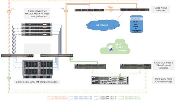
This section introduces the devices used in validating the solution described in this document (Figure 2):
● Cisco HyperFlex cluster (x 1) composed of:
◦ Cisco HyperFlex HX220c M5SX All Flash converged node (x 4)
◦ Cisco UCS B200 M4 Blade Server computing-only node (x 2) (in a Cisco UCS 5108 Blade Server Chassis with dual Cisco UCS 2208 Fabric Extender I/O modules)
◦ Cisco UCS 6454 Fabric Interconnect (x 2)
● Cisco Nexus® 93180YC-EX Switch (x 2)
● Cisco MDS 9396S 16G Multilayer Fabric Switch (x 2)
● Third-party Fibre Channel storage array (x 1)
● Cisco Intersight Cloud Management Platform (for Cisco HyperFlex installation)
Validation testing setup
Table 1 lists the converged node specifications.
Table 1. Cisco HyperFlex HX220c M5SX All Flash Node specifications
| Components |
Specifications |
Notes |
| CPU |
2 x Second Generation Intel® Xeon® Gold 6248 CPUs |
2 x 20 cores |
| Memory |
12 x 32-GB DDR4 2933-MHz RDIMMs |
384 GB |
| Disk controller |
1 x Cisco 12-Gbps modular SAS HBA |
|
| SSD |
1 x 240-GB 2.5-inch Enterprise Value 6-GB SATA SSD |
Housekeeping |
|
|
1 x 1.6-TB 2.5-inch NVMe High-Performance High-Endurance SSD |
Configured as cache |
|
|
6 x 960-GB 2.5-inch Enterprise Value 6-GB SATA SSDs |
Capacity disks for each node |
| Network |
1x Cisco UCS VIC1457 modular LAN on motherboard (mLOM) |
25 Gigabit Ethernet |
| Boot device |
1 x 240-GB M.2 6-GB SATA SSD |
Local boot |
Table 2 lists the computing-only node specifications.
Table 2. Cisco UCS B200 M4 computing-only node specifications
| Components |
Specifications |
Notes |
| CPU |
2 x Intel Xeon processor E5-2680 v4 CPUs |
2 x 14 cores |
| Memory |
16 x 32-GB DDR4 2400-MHz RDIMMs |
512 GB |
| Disk controller |
None |
|
| Disks |
None |
|
| Network |
1x Cisco UCS VIC1340 VIC mLOM |
|
| Boot device |
1 x 128-GB remote disk from third-party storage array |
SAN boot |
Table 3 lists the software versions used in the test environment described in this document.
Table 3. Test environment software versions
| Layer |
Device |
Version |
| Computing |
Cisco UCS 6454 Fabric Interconnect pair |
Release 4.0(4d) |
|
|
Cisco HyperFlex HX220c M5SX All Flash Node firmware |
Release 4.0(4d) |
|
|
Cisco UCS B200 M4 computing-only node firmware |
Release 4.0(4d) |
| Network |
Cisco Nexus 93180YC-EX Switch pair (LAN upstream) |
Release 7.0(3)I4(2) |
|
|
Cisco MDS 9396S 16G Multilayer Fabric Switch pair (Fibre Channel SAN upstream) |
Release 8.4(1) |
| Software |
Cisco UCS Manager |
Release 4.0(4d) |
|
|
Cisco HyperFlex HX Data Platform software |
Release 4.0(1b) |
|
|
VMWare vSphere ESXi |
Release 6.5.0, 13932383 |
|
|
VMWare vSphere vCenter |
Release 6.5.0.32000 |
Connecting Cisco HyperFlex to Fibre Channel shared storage
With Cisco HyperFlex systems, customers have the flexibility to use other storage infrastructure by mapping the other storage to the Cisco HyperFlex system. For example, you can map Fibre Channel LUNs on a storage system and then use VMware Storage vMotion to easily move virtual machines between the two systems.
The following are the high-level configuration steps for connecting the Cisco HyperFlex system to an external SAN storage system:
1. Rack and cable the system, connecting the unified ports on the Cisco UCS fabric interconnects to the Fibre Channel switch ports correctly.
2. Configure the unified ports on the Cisco UCS fabric interconnects as Fibre Channel uplink ports. In many cases, this configuration is disruptive and will cause the Cisco UCS fabric interconnect to reboot.
3. Configure the ports on the Cisco MDS Fibre Channel switches with the correct type and VSAN membership if necessary, and bring up the links between Cisco UCS fabric interconnects and Fibre Channel switches. Enable the NPIV feature on the Cisco MDS switches and also the F_Port-channel-trunk feature if you want the links to come up as a Fibre Channel port channel.
4. Enable Fibre Channel connectivity and create vHBAs on the Cisco HyperFlex cluster and verify that the vHBAs log in correctly to the Fibre Channel switches.
5. Generate the device alias for the vHBA ports and storage ports, create the device-alias zones, and activate the zone set on the Fibre Channel switches to grant the vHBAs access to the storage system.
6. Configure the Fibre Channel storage system so that the designated LUNs are masked in such a way that they are visible and accessible to all the Cisco HyperFlex hosts.
7. In VMware vCenter, scan the shared LUNs from the Cisco HyperFlex cluster and then create the data stores. The SAN storage volumes are now available for use by the Cisco HyperFlex cluster.
To connect to other storage systems through the Fibre Channel SAN, you should add vHBAs as part of the installation while creating the Cisco HyperFlex cluster. If you add these after the clusters have been created, use care to modify the configuration of the Cisco HyperFlex nodes one by one so you do not cause the entire cluster to drop offline unexpectedly. The discussion here documents the addition of Fibre Channel vHBAs to Cisco HyperFlex hosts. There are two basic methods, covered here. The first method is to add the adapters prior to creating the cluster, and the second method is to add the adapters after creating the cluster.
Bringing up Fibre Channel uplinks on Cisco UCS fabric interconnects
In all deployment scenarios, the connectivity between the Cisco UCS fabric interconnects and the upstream Cisco MDS switches must be established first. You should perform these domainwide configuration steps before you deploy Cisco HyperFlex systems whenever possible, because changing the mode of the unified ports from Ethernet to Fibre Channel, or vice versa, will often result in the reboot of the fabric interconnects. Only the add-in modules of first- and second-generation Cisco UCS fabric interconnects can be independently rebooted. All changes to port modes on third- and fourth-generation Cisco UCS fabric interconnects will result in the reboot of the entire device. After connectivity between the Cisco UCS fabric interconnects and the Cisco MDS switches is established, then you can install the Cisco HyperFlex system with additional vHBAs, or alternatively you can modify the service profiles of an existing Cisco HyperFlex cluster.
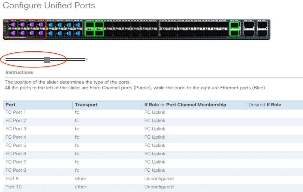
Configure unified ports
The Cisco UCS 6454 Fabric Interconnects have a slider mechanism in the Cisco UCS Manager GUI that controls the first sixteen ports, starting from the first port, configuring in increments of four unified ports. To enable the Fibre Channel uplink ports on the Cisco UCS 6454 switches, follow this procedure:
1. In Cisco UCS Manager, click the Equipment tab in the navigation pane.
2. Select Equipment > Fabric Interconnects > Fabric Interconnect A (primary).
3. Select Configure Unified Ports.
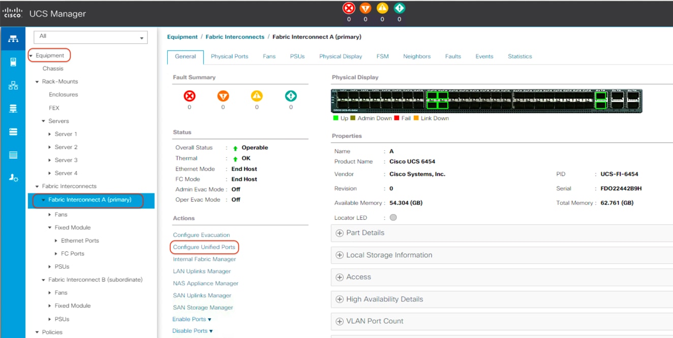
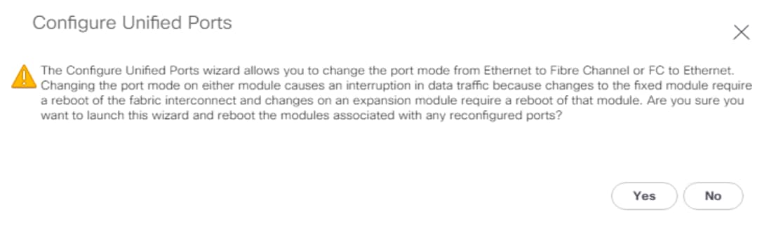
4. Click Yes in the pop-up window warning that changes to the fixed module will require a reboot of the fabric interconnect and changes to the expansion module will require a reboot of that module.
5. In the Configure Unified Ports pop-up window, move the gray slider bar from the left to the right to select ports, from ports 1 to 16, to be set as Fibre Channel uplinks in four-port increments.
6. Click OK to continue. The fabric interconnect will reboot and reconnect to Cisco UCS Manager.
7. Select Equipment > Fabric Interconnects > Fabric Interconnect B (subordinate).
8. Select Configure Unified Ports.
9. Click Yes in the pop-up window warning that changes to the fixed module will require a reboot of the fabric interconnect and changes to the expansion module will require a reboot of that module.
10. In the Configure Unified Ports pop-up window, move the gray slider bar from the left to the right to select the same amount of unified ports, from ports 1 to 16, to be set as Fibre Channel uplinks in four-port increments..
11. Click OK to continue. The fabric interconnects will reboot and reconnect to Cisco UCS Manager.
Create VSANs
To configure the necessary VSANs for the Cisco UCS environment, follow this procedure:
1. In Cisco UCS Manager, click the SAN tab in the navigation pane.
2. Select SAN > SAN Cloud > Fabric A.
3. Right-click VSANs.
4. Select Create VSAN.
5. Enter VSAN_A as the name of the VSAN to be used for Fabric A.
6. Leave Disabled selected for FC Zoning.
7. Select Fabric A.
8. Enter a unique VSAN ID and a corresponding FCoE VLAN ID. The recommended approach is to use the same ID for both and not to use any number other than 1. This VSAN ID must match the ID number used in the upstream connected Cisco MDS switches. For example, if the uplinks from the Cisco fabric interconnects are plugged into Cisco MDS switch ports that are members of VSAN 202, you must create VSAN 202 within Cisco UCS Manager.
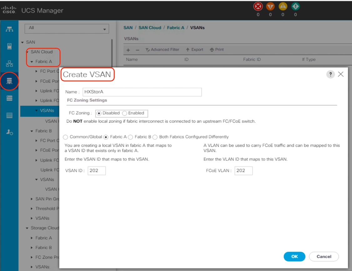
9. Click OK and then click OK again.
10. Select SAN > SAN Cloud > Fabric B.
11. Right-click VSANs.
12. Select Create VSAN.
13. Enter VSAN_B as the name of the VSAN to be used for Fabric B.
14. Leave Disabled selected for FC Zoning.
15. Select Fabric B.
16. Enter a unique VSAN ID and a corresponding FCoE VLAN ID. The recommended approach is to use the same ID for both and to use a number other than 1. This VSAN ID must match the ID number used in the upstream connected Cisco MDS switches. For example, if the uplinks from the Cisco fabric interconnects are plugged into Cisco MDS switch ports that are members of VSAN 201, you must create VSAN 201 within Cisco UCS Manager.
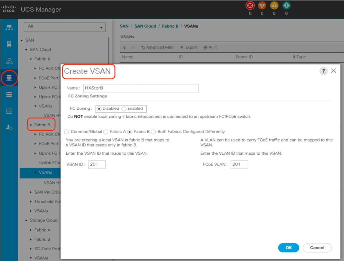
17. Click OK and then click OK again.
Create Fibre Channel port channels
You should configure the Fibre Channel port channels for the Cisco UCS environment. Follow this procedure:
1. In the navigation pane under SAN > SAN Cloud, expand the Fabric A tree.
2. Right-click FC Port Channels.
3. Select Create FC Port Channel.
4. Enter the port channel ID and the port channel name for Fabric A.
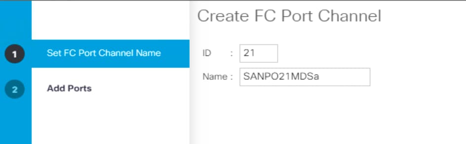
5. Click Next. Then choose appropriate ports and click >> to add the ports to the port channel.
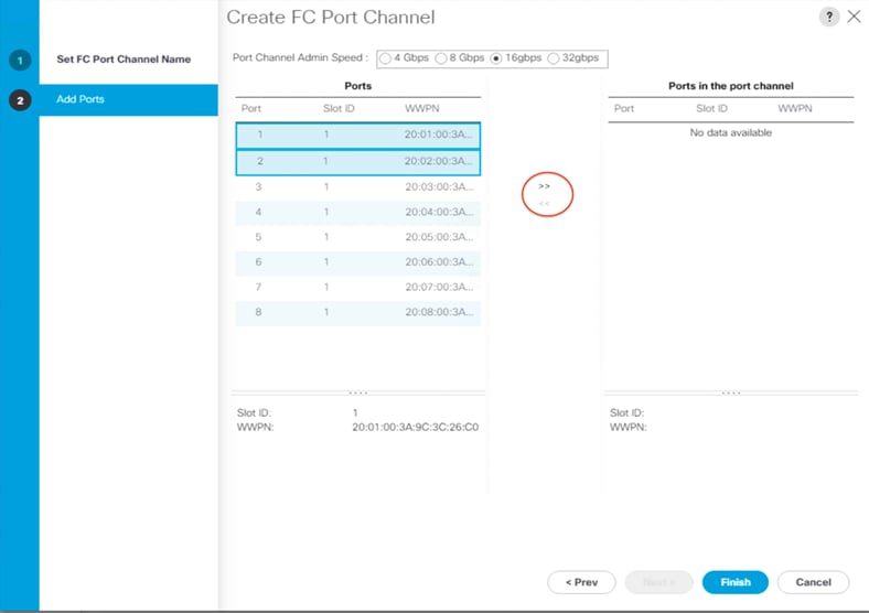
6. Click Finish.
7. Click OK.
8. Select the newly created port channel.
9. From the VSAN drop-down list for this port channel, select the previously created VSAN for Fabric A.
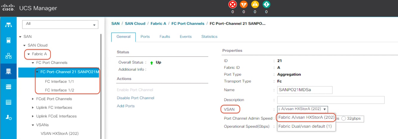
10. Click Save Changes and then click OK.
11. In the navigation pane under SAN > SAN Cloud, expand the Fabric B tree.
12. Right-click FC Port Channels.
13. Select Create Port Channel.
14. Enter the port channel ID and the port channel name for Fabric B.
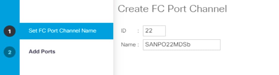
15. Click Next. Then choose the appropriate ports and click >> to add the ports to the port channel.
16. Click Finish.
17. Click OK.
18. Select the newly created port channel for Fabric B.
19. From the VSAN drop-down list for this port channel, select the previously created VSAN for Fabric B.
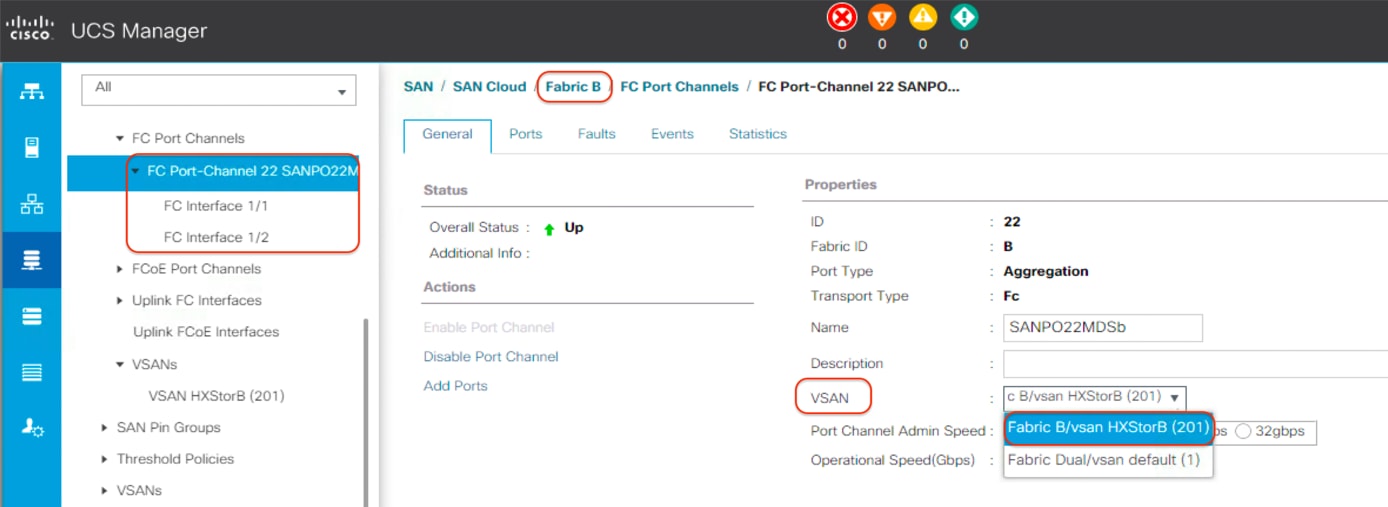
20. Click Save Changes and then click OK.
Configure Cisco MDS switches
Now configure the Cisco MDS switches.
1. First enable the necessary features and settings on both Cisco MDS switches:
On the Cisco MDS switches, create the VSANs that are used for connectivity to the Cisco UCS fabric interconnects and the storage system. These VSANs will be assigned to the interfaces that will connect to the storage array as well as to the interfaces and the port channels that are connected to the Cisco UCS fabric interconnect. In many cases, the VSAN will already exist and be in use for connectivity to an existing storage array. In such cases, only the new interfaces from the Cisco UCS fabric interconnects need to be added to the existing VSAN membership.
2. Use this configuration to create VSANs and interfaces on both Cisco MDS switches:
3. Now configure the Fibre Channel port channels and add the interfaces to them on both Cisco MDS switches:
Adding vHBAs during Cisco HyperFlex cluster creation
For HX Data Platform 2.0 and later, the Cisco HyperFlex installation process supports the configuration of vHBAs as part of cluster creation. The Cisco HyperFlex installer can guide you through the process of setting up your Cisco HyperFlex cluster, allowing you to use existing third-party storage through the Fibre Channel protocol. It will automatically configure Cisco UCS profiles and Cisco HyperFlex cluster nodes with vHBAs and correct VSAN and WWPN assignments, simplifying the setup process.
For HX Data Platform 2.6 and later, the monitoring, installation, and management of the Cisco HyperFlex cluster is supported with the Cisco Intersight cloud platform. The Cisco Intersight platform provides an installation wizard to install, configure, and deploy Cisco HyperFlex clusters. The wizard constructs a preconfiguration definition of a Cisco HyperFlex cluster called a Cisco HyperFlex cluster profile. The cluster profile is policy based, with administrator-defined sets of rules and operating characteristics such as the node identity, interfaces, and vCenter connectivity. Every active node in the Cisco HyperFlex cluster must be associated with a Cisco HyperFlex cluster profile. After the user enters all configuration settings, the installation wizard will validate and deploy the cluster profile on the Cisco HyperFlex nodes. You can clone a successfully deployed Cisco HyperFlex cluster profile and then use that copy as the basis for easily creating many more new clusters at the same site or at the remote site.
A Cisco HyperFlex system can be deployed by using an on-premises Cisco HyperFlex Installer appliance, or by using the Cisco Intersight platform from the cloud. This document describes only the installation process using the Cisco Intersight cloud platform.
Claim devices in the Cisco Intersight platform
Enable the device connector on the Cisco UCS fabric interconnects and then let the Cisco Intersight platform claim them for cloud management:
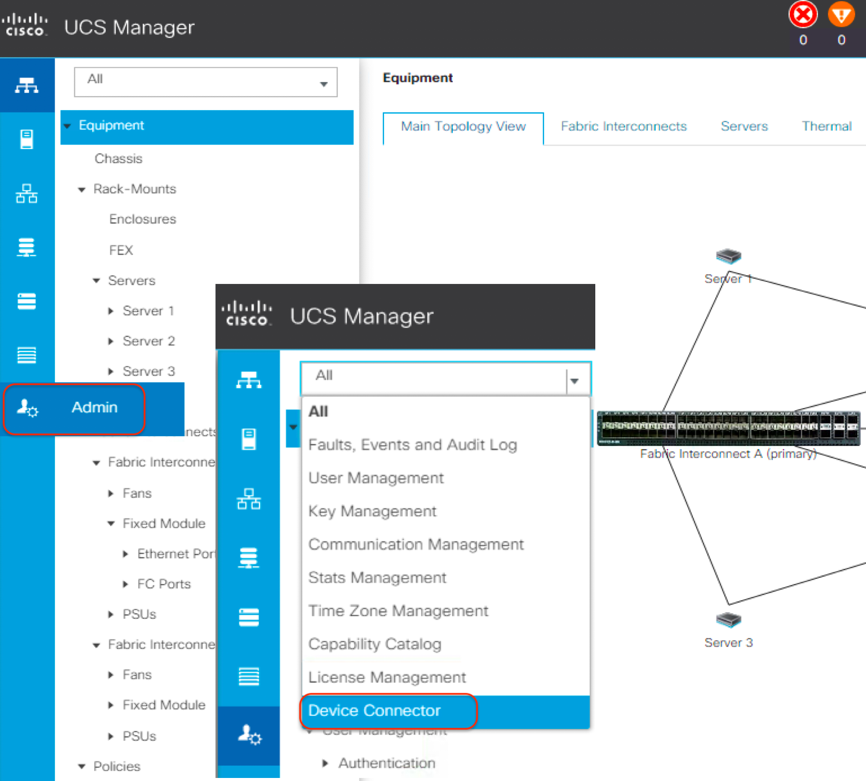
1. Log in to the Cisco UCS Manager web management GUI with https://<UCSM-IP-Address>.
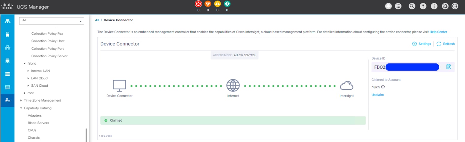
2. In the navigation pane, expand Admin. Then click Device Connector to turn on the device connector to enable Cisco Intersight management. This step enables the Cisco UCS management panel to establish a connection with the Cisco Intersight platform.
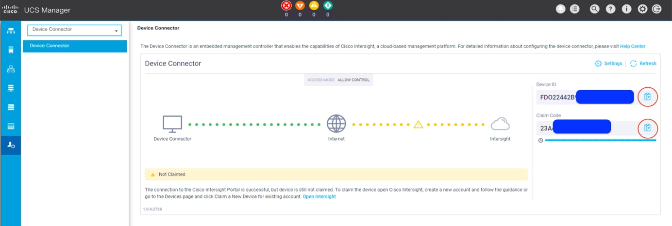
3. Wait until the connection succeeds and a claim code has been generated for this device. Note that the device is not claimed yet. Note the device ID and claim code because you will need them in a subsequent step. You can use the copy-and-paste method to obtain the values accurately by clicking the Copy icon at the right side of the values. Those values will then be placed on the clipboard, and you can paste them anywhere.
4. Open a web browser and navigate to the Cisco Intersight cloud management platform: https://intersight.com/.
5. Log in with your Cisco ID and password. If this is your first time using the Cisco Intersight platform, you should take a site tour to learn about some of the platform’s main features.
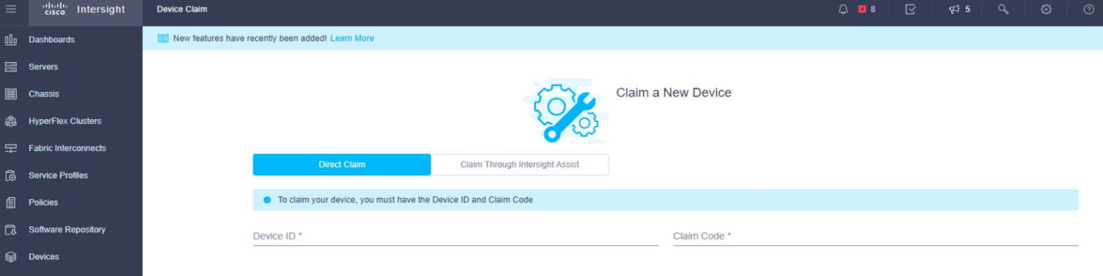
6. To claim a new device, in the left navigation pane click Devices. In the Device window, choose Claim a New Device at the top right.
7. Enter the device ID and claim code obtained from Cisco UCS Manager device connector. Use copy and paste to help ensure accuracy. Click Claim.
8. Wait until the device is claimed successfully.
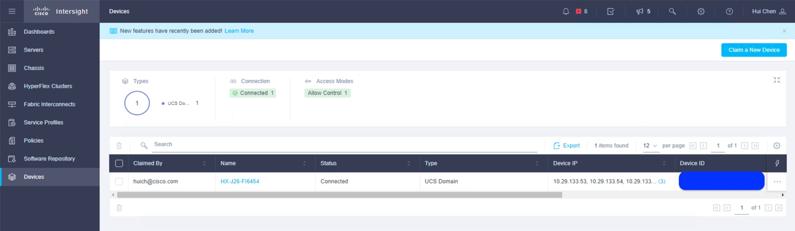
9. Go to the Cisco UCS Manager Device Connector page to verify the status. The Device Connector page now shows that this device is claimed.
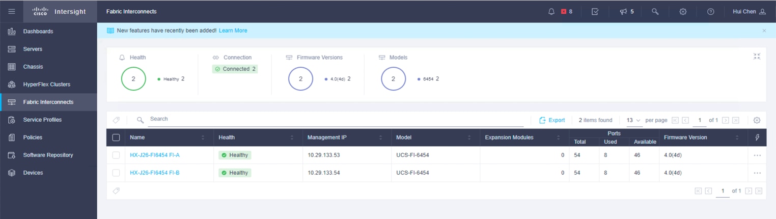
10. In the Fabric Interconnects window of the Cisco Intersight platform, both UCS FI-A and FI-B are connected.
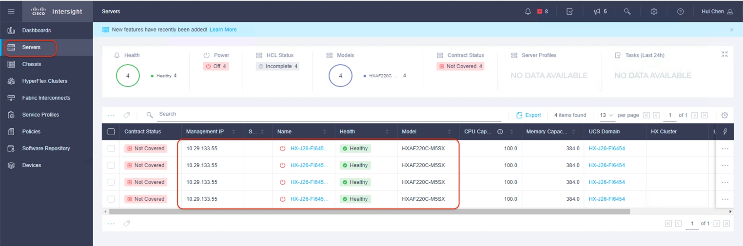
11. In the Servers window of the Cisco Intersight platform, four Cisco HyperFlex nodes should now be shown as connected devices.
Install the Cisco HyperFlex cluster
To install and configure a Cisco HyperFlex cluster with the Cisco Intersight platform, complete the following steps:
1. Log in to the Cisco Intersight cloud management platform from https://intersight.com/ with your Cisco ID and password.
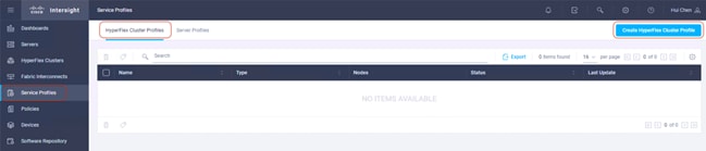
2. In the left navigation pane, choose Service Profiles. On the Service Profiles page, click the HyperFlex Cluster Profiles tab and then click Create HyperFlex Cluster Profile.
3. The Cisco HyperFlex Cluster Profile installation wizard is displayed. On the General page, enter a cluster name under Name. This cluster name must be unique and will be used as the Cisco HyperFlex cluster name, VMware vCenter cluster name, and Cisco Intersight cluster name. Select the appropriate HX Data Platform version. Under Type, select Cisco HyperFlex with Fabric Interconnect. Choose 3 for Replication Factor. Add a description and tags for this cluster for reference.
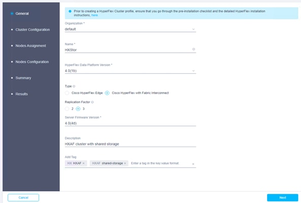
4. Click Next to move to the Cluster Configuration page.
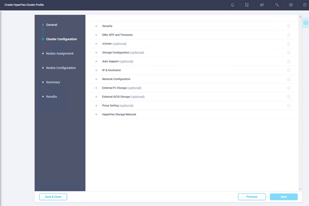
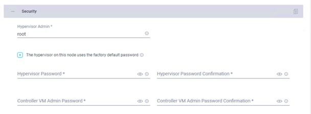
5. Click + to expand the Security configuration. Enter root as the hypervisor administrative user. Click the check box if the hypervisor on this node uses the factory default password. Enter a user-supplied new password for the hypervisor and a user-supplied password for the Cisco HyperFlex controller virtual machine. Confirm that password in the second text field. The settings will be saved automatically to a policy, which you can reuse when you create a new Cisco HyperFlex cluster profile.
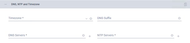
6. Click + to expand the DNS, NTP and Timezone configuration. Choose a time zone from the drop-down list and enter the Domain Name System (DNS) server and Network Time Protocol (NTP) server information. Click + to enter secondary DNS or NTP servers if necessary.
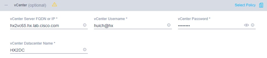
7. Click + to expand the vCenter configuration. Enter the vCenter server fully qualified domain name (FQDN) or IP address, the administrative username, and the password. Enter the name of the vCenter data center that is hosting the Cisco HyperFlex cluster.
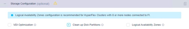
8. Click + to expand Storage Configuration. Select Clean Up Disk Partitions if you are performing a reinstallation on top of an existing deployment. If you are deploying a virtual desktop infrastructure (VDI) environment on a hybrid Cisco HyperFlex cluster, check the box to enable file system optimizations.
9. Click + to expand the Auto Support configuration. Check the box to enable Auto-Support. Enter your email address for service ticket notification.

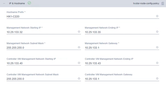
10. Click + to expand the IP & Hostname configuration. Enter a host name prefix. In a later step, host names will be assigned sequentially to hosts using this prefix. Enter a starting IP address, an ending IP address, and the subnet mask and gateway for the management IP address pool. IP addresses from this range will automatically be assigned to hosts during the node configuration step. If you enter only the management network IP addresses, the same range will be used for both VMware ESXi management and Cisco HyperFlex controller virtual machine management IP addresses. If you want to use a second, noncontiguous range of IP addresses for the Cisco HyperFlex controller virtual machines, you can optionally enter starting and ending IP addresses and the subnet mask and gateway for the Cisco HyperFlex controller virtual machine management IP address pool. Note that these two IP address ranges must fall within the same IP subnet and VLAN.
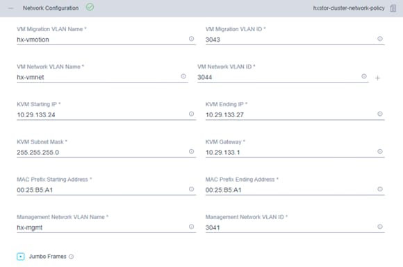
11. Click + to expand Network Configuration. Enter the VMotion VLAN name and VLAN ID. Enter the guest virtual machine network VLAN name and VLAN ID. Click + at the right to add input for multiple guest virtual machine networks if necessary. Enter a starting IP address, an ending IP address, and the subnet mask and gateway for the Kernel-based Virtual Machine (KVM) management IP address pool. IP addresses from this range will automatically be assigned to hosts during the node configuration step. Enter MAC prefix starting and ending addresses. Enter the VLAN ID for the management network. Click the Jumbo Frames checkbox unless you want to do otherwise.
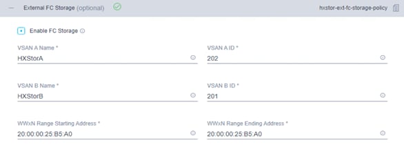
12. Click + to expand the FC Storage configuration. Click the Enable FC Storage checkbox. Enter the VSAN name and VSAN ID for Fabric A and Fabric B. The VSAN IDs should match those previously created on the Cisco MDS switches and Cisco UCS fabric interconnects. Enter a starting address and an ending address for the WWxN pool. World Wide Node Names (WWNNs) and WWPNs from this pool will automatically be assigned to the vHBAs created on the Cisco HyperFlex hosts.
13. Leave the optional External iSCSI Storage configuration blank.
14. Leave the optional Proxy Setting blank.
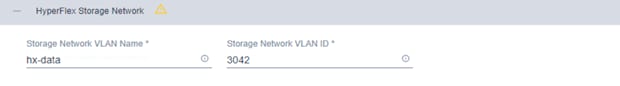
15. Click + to expand the HyperFlex Storage Network configuration. Enter the VLAN name and ID for the data storage network.
16. Now that all the policies are configured, and the saved policies will be listed in this page.
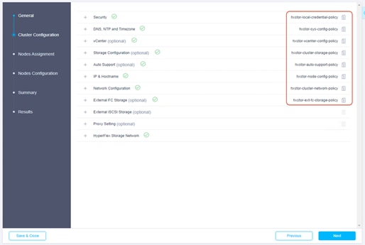
17. Click Next to proceed to the Nodes Assignment page.
18. Select the available Cisco HyperFlex nodes.
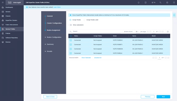
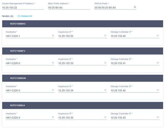
19. Click Next to navigate to the Nodes Configuration page. Check the node configuration for all the Cisco HyperFlex nodes. You can freely modify the host names of automatic IP address assignments if desired. Enter the cluster management IP address in the same IP management subnet.
20. Click Next to move to the Summary page. Review the Cluster Configuration and Nodes Configuration pages. Look for any errors.
21. Click Validate to validate the Cisco HyperFlex cluster configuration only, without starting deployment. This step will start a series of hardware, software, and environmental checks that will take a few minutes to complete. Alternatively, click Validate & Deploy to complete the validation and deployment processes together. In this document, the validation and deployment processes are performed in one step.
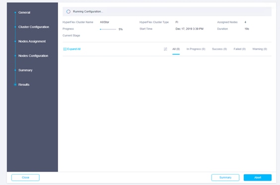
22. You can remain on the results page to watch cluster deployment progress in real time. Alternatively, you can click Close to send the task to the background and navigate elsewhere within the Cisco Intersight platform. To return to this results view, navigate back to the Service Profiles > HX Cluster Profile list view and select the cluster name.
23. After deployment has completed successfully, click OK.
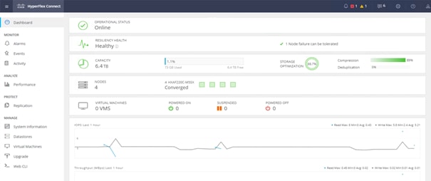
24. You can review more detailed status information for the new Cisco HyperFlex cluster in the Cisco HyperFlex Connect management GUI. You can launch Cisco HyperFlex Connect from the Cisco Intersight platform, or you can launch it directly with https://<HX-Cluster-Management-IP-Address>.
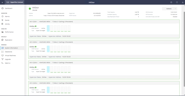
25. At the Cisco HyperFlex Connect management console, click System Information and verify the status of the Cisco HyperFlex cluster and nodes.
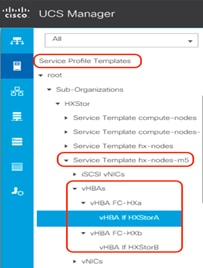
26. After the installation is complete, dual vHBAs are created for the service template hx-nodes-m5.
27. For each Cisco HyperFlex node, dual vHBAs also are created from the cluster creation.
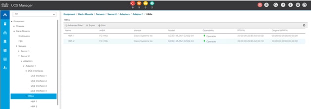
28. In vCenter, verify that dual virtual machine HBAs are created for each Cisco HyperFlex host.
29. Before you put a new Cisco HyperFlex cluster into production, complete the necessary post-installation tasks as described in the Cisco HyperFlex documentation.
Adding vHBAs after the Cisco HyperFlex cluster is created
Adding or removing vHBAs on the ESXi host will cause PCI address shifting upon reboot. This shift can cause the PCI passthrough configuration on the Cisco HyperFlex node to no longer be valid, and the Cisco HyperFlex controller virtual machine will not boot. Thus, you should avoid making such hardware changes after the Cisco HyperFlex cluster is created. A better option is to add vHBAs, if necessary, during the process while the cluster is being created.
However, should you decide to add storage after you have already installed your cluster, you can use the following procedure to add vHBAs or certain vNICs that could cause PCI re-enumeration on ESXi reboot. This process can create passthrough device failure, and Cisco HyperFlex controllers will not boot, so as a best practice you should not reboot multiple nodes at the same time after making such hardware changes. Validate the health state of each system before rebooting or performing the procedure on subsequent nodes. In this example, you will add vHBAs after a cluster is created through the Cisco UCS profile service template. You will reboot one ESXi Cisco HyperFlex node at a time, in a rolling upgrade, so there will be no outage.
Note: Adding virtual adapter interfaces to the VIC card on the Cisco HyperFlex nodes may cause disruption on the system. Read the following procedure carefully before implementing it.
To add vHBAs to all the hosts in the existing Cisco HyperFlex cluster in the Cisco UCS environment, complete the following procedure.
Create the WWNN pool
Use these steps to create a WWNN pool:
1. To configure the necessary WWNN pool, in Cisco UCS Manager select the SAN tab.
2. Select Pools > root.
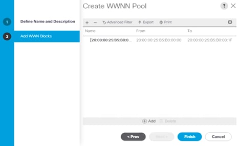
3. Right-click WWNN Pools. Select Create WWNN Pool to create the WWNN pool.
4. Enter the name of the WWNN pool.
5. Enter a description for the WWNN pool if necessary.
6. For Assignment Order, select Default.
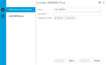
7. Click Next.
8. In the Add WWN Blocks window, click Add.
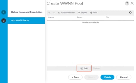
9. Modify the From field as necessary for the Cisco UCS environment.
10. Specify a size for the WWN block sufficient to support the available server resources.
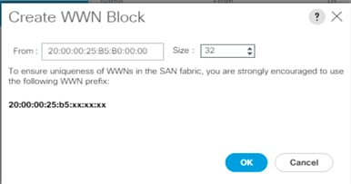
11. Click OK.
12. Click Finish to create the WWNN pool.
13. Click OK.
Create the WWPN pool
Use these steps to create a WWPN pool:
1. To configure the necessary WWPN pool, in Cisco UCS Manager select the SAN tab in the navigation pane.
2. Select Pools > root.
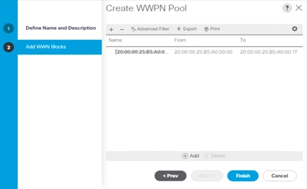
3. Right-click WWPN Pools under the root organization. Select Create WWPN Pool to create the WWPN pool.
4. Enter the name of the WWPN pool.
5. Enter a description for the WWPN pool if necessary.
6. For Assignment Order, select Default.

7. Click Next.
8. In the Add WWN Blocks window, click Add.

9. Modify the From field as necessary for the Cisco UCS environment.
10. Specify a size for the WWPN block sufficient to support the available server resources.
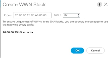
11. Click OK.
12. Click Finish to create the WWPN pool.
13. Click OK.
14. Optionally, you can create two WWPN pools: one for Fabric A, and a second one for Fabric B.
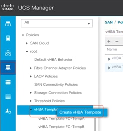
Create vHBA templates
To configure the necessary vHBA templates for the Cisco UCS environment, follow these steps:
1. In Cisco UCS Manager, click the SAN tab in the navigation pane.
2. Select Policies > root.
3. Right-click vHBA Templates. Select Create vHBA Template.
4. Enter the vHBA template name for Fabric A.
5. Keep Fabric A selected.
6. Leave Redundancy Type as No Redundancy.
7. Select the VSAN previously created for Fabric A.
8. Leave Initial Template as the template type.
9. Select the WWPN pool that you just created.
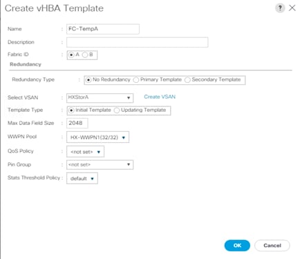
10. Click OK to create the vHBA template for Fabric A.
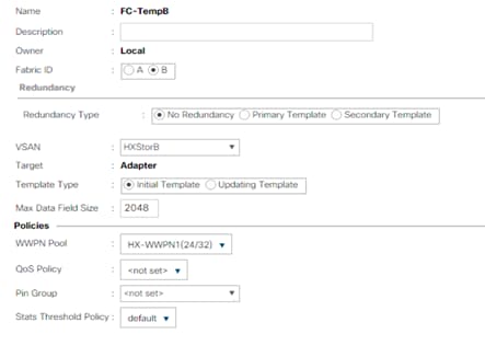
11. Repeat steps 1 to 10 to create the vHBA template for Fabric B.
12. Click OK.
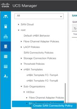
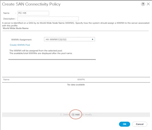
Create SAN connectivity policy
To configure the necessary infrastructure SAN connectivity policy, follow these steps:
1. In Cisco UCS Manager, click the SAN tab in the navigation pane.
2. Select SAN > Policies > root > Sub-Organizations.
3. Select the suborganization for the Cisco HyperFlex cluster.
4. Right-click SAN Connectivity Policies.
5. Select Create SAN Connectivity Policy.
6. Enter the name of the policy.
7. Select the previously created WWNN pool for the WWNN assignment.
8. Click the Add button at the bottom of the screen to add a vHBA for Fabric A.
9. In the Create vHBA dialog box, enter the name of the vHBA for Fabric A.
10. Select the Use vHBA Template checkbox.
11. Leave Redundancy Pair unselected.
12. In the vHBA Template list, select the vHBA template previously created for Fabric A.
13. In the Adapter Policy list, select VMWare.
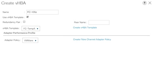
14. Click OK.
15. On the Create SAN Connectivity Policy page, repeat steps 8 to 13 to add a vHBA for Fabric B.
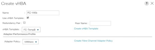
16. Click OK.
Apply SAN connectivity policy
Now assign this SAN connectivity policy to the Cisco HyperFlex service profile template.
1. In Cisco UCS Manager, click the Servers tab in the navigation pane.
2. Select Servers > Service Profile Templates > root > Sub-Organizations.
3. Select the suborganization for the Cisco HyperFlex cluster.
4. Click Service Templates hx-nodes-m5 for Cisco HyperFlex M5 rack servers, or Service Templates hx-nodes for Cisco HyperFlex M4 rack servers. If present, the service profile templates for the computing-only nodes must be modified as well.
5. From the SAN Connectivity Policy drop-down list, select the SAN connectivity policy that you just created.
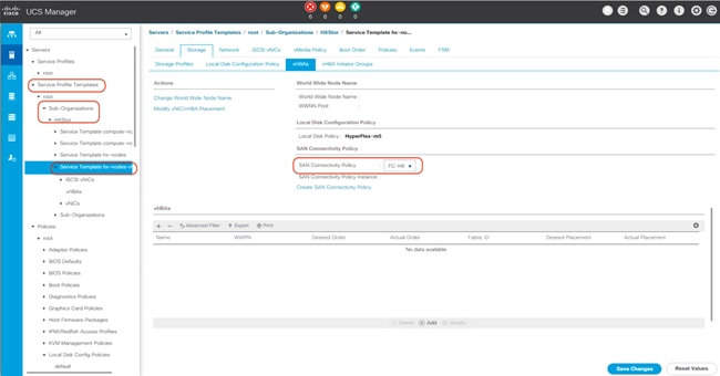
6. Click Save Changes.
7. Click Yes to apply the changes to the service profiles.
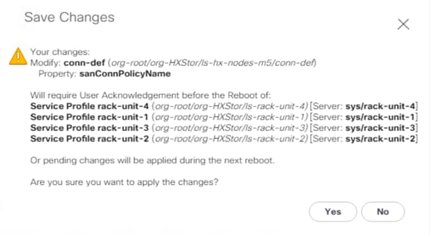
8. After you have finished adding HBAs to the templates, the servers will require a reboot. Do NOT reboot the Cisco HyperFlex servers at this time.
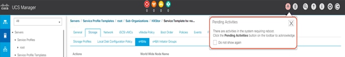
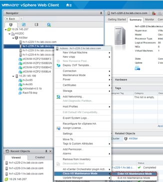
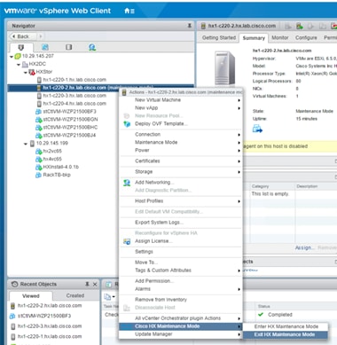
9. Using the vSphere Web Client, place one of the Cisco HyperFlex system ESXi hosts in Cisco HyperFlex maintenance mode.
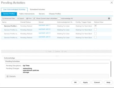
10. After the host has entered maintenance mode, go back to the Cisco UCS Manager management GUI, open Pending Activities, click the Reboot Now checkbox for that single host, and then apply the selection to reboot the associated node to complete the addition of the new hardware. Before the acknowledgment, double-check to make sure that the right server is about to reboot.
11. After the node has rebooted, the HX Data Platform software will detect that the DirectPath I/O configuration has changed and must be reconfigured. This detection will result in one additional automatic reboot of the node.
12. After the second reboot, exit the ESXi host from maintenance mode. The software-defined virtual machine (SCVM) should start automatically without errors.
13. Check the health status of the cluster from Cisco HyperFlex Connect, verifying that the cluster is healthy before proceeding to reboot the next node.
14. Repeat steps 9 to 13 for each node in the cluster as necessary, until all of the nodes have been rebooted and the new vHBAs are present.
Connecting to an external Fibre Channel data store
The following procedure demonstrates a scenario in which a newly built or existing Cisco HyperFlex cluster connects to an existing third-party Fibre Channel storage device. The Cisco HyperFlex system is built with its own fabric interconnect switches and then connected to the upstream Fibre Channel switches where the existing storage devices are also connected. For a different scenario, in which Cisco HyperFlex nodes are added to the existing fabric interconnect domain, you must exercise caution and plan properly, because the Cisco HyperFlex installer will overwrite any conflicting configurations in the existing Cisco UCS domain: for example, quality-of-service (QoS) policy. This process may require an upgrade of the Cisco UCS firmware or a change in the configuration of the upstream switches as well. All these changes can be disruptive to the existing production environment and need to be carefully planned and implemented within a maintenance window. You should contact your Cisco support team to make this kind of change when you need to connect Cisco HyperFlex nodes to the existing fabric interconnect domain.
In this document, Cisco MDS Fibre Channel switches are connected to the Cisco UCS fabric interconnects, which are configured with some unified ports in end-host Fibre Channel mode. The third-party storage is connected to the Cisco MDS switches. The VSAN IDs generated for the Cisco HyperFlex cluster in the procedure described here must be identical to the VSAN IDs being used in your current environment for the storage device that is configured on the Cisco MDS switches.
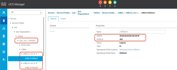
1. Open Cisco UCS Manager, expand Servers > Service Profiles > root > Sub-Organizations, click the Cisco HyperFlex suborganization, expand the service profile of the first Cisco HyperFlex server, and check the vHBA information for Fabric A.
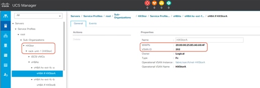
2. Open Cisco UCS Manager, expand Servers > Service Profiles > root > Sub-Organizations, click the Cisco HyperFlex suborganization, expand the service profile of the first Cisco HyperFlex server, and check the vHBA information for Fabric B.
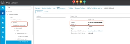
3. Repeat steps 1 and 2 for all the Cisco HyperFlex nodes. Then record the WWPNs in the chart in Table 4. You will need this information later for zone configuration on the Fibre Channel switches. You can copy the WWPN value by clicking the vHBA in Cisco UCS Manager and then, in the right pane, right-clicking the WWPN to copy it. For each WWPN, you can create a unique alias and use it as part of the Fibre Channel zone configuration. Aliases can be easier to remember than the WWPNs. For example, you might create aliases HXnode1-vHBA1 and HXnode1-vHBA2.
Table 4. WWPNs on Cisco HyperFlex hosts
| Items |
|
Fabric A |
Fabric B |
| Cisco HyperFlex converged node 1 |
WWPN |
|
|
| Alias |
|
|
|
| Cisco HyperFlex converged node 2 |
WWPN |
|
|
| Alias |
|
|
|
| Cisco HyperFlex converged node 3 |
WWPN |
|
|
| Alias |
|
|
|
| Cisco HyperFlex converged node 4 |
WWPN |
|
|
| Alias |
|
|
|
| Cisco HyperFlex computing-only node 5 |
WWPN |
|
|
| Alias |
|
|
|
| Cisco HyperFlex computing-only node 6 |
WWPN |
|
|
| Alias |
|
|
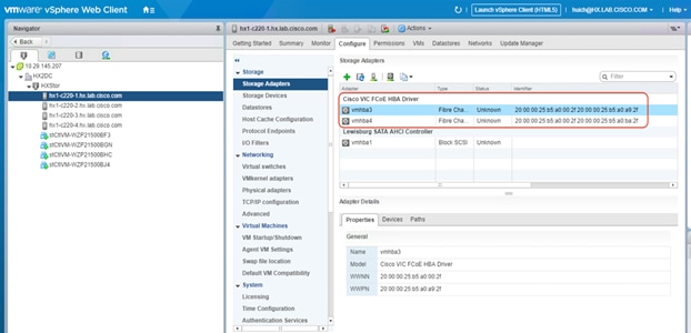
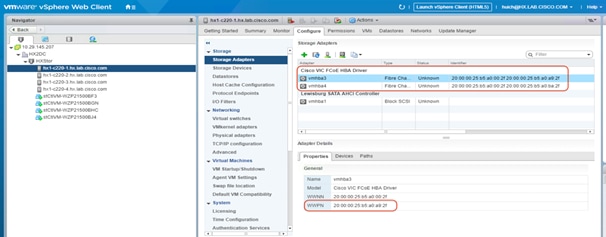
4. Alternatively, you can obtain the WWPN value on the ESXi host in vCenter on the Configuration tab. Choose Storage Adapters > Cisco VIC FCoE HBA Driver > <<vmhba>>.
5. You must also record the WWPNs for the storage ports, using the chart in Table 5, because you will need them later for zone configuration on the Fibre Channel switches. This information can be found using your storage device’s management tool. As with the WWPNs you can create aliases, such as Controller1-port1A and Controller1-port2B.
Table 5. Storage WWPNs
| Items |
|
Fabric A |
Fabric B |
| Storage device port 1 |
WWPN |
|
|
| Alias |
|
|
|
| Storage device port 2 |
WWPN |
|
|
| Alias |
|
|
|
| Storage device port 3 |
WWPN |
|
|
| Alias |
|
|
|
| Storage device port 4 |
WWPN |
|
|
| Alias |
|
|
Note: In most deployments, the redundant connectivity of a storage array or controller uses multiple connections to both sides of the Fibre Channel network. For example, port 1 here would be connected to Fabric A only and not to Fabric B; meanwhile, port 2 would be connected to Fabric B only and not Fabric A. Likewise, port 3 would be connected to Fabric A, and port 4 would be connected to Fabric B.
6. Log in to the Cisco MDS switch for Fabric A (MDS A) and verify that all Cisco HyperFlex vHBAs for Fabric A have logged in to the name server and that they are in the same VSAN as the target storage ports.
7. Complete the following configuration to create the WWPN aliases using the values from the table.
8. Create the WWPN aliases for the storage devices if necessary.
9. Create the zones and add device-alias members (or WWPN members) for the Cisco HyperFlex servers.
10. Create a zone set and add the zones.
11. Activate the zone set.
12. Validate the active zone set and verify that all Cisco HyperFlex vHBAs and the target storage ports are logged in to the switch (verify that * appears next to the devices).
13. Log in to the Cisco MDS switch for Fabric B (MDS B) and complete the zoning process as in steps 7 to 13.
14. Create host groups for the Cisco HyperFlex nodes, create volumes on the storage system, and map the volumes to the host group. Follow your storage vendor’s documentation to complete these processes.
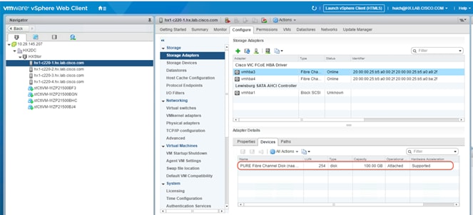
15. Return to vCenter and verify that the provisioned volume is attached to the Cisco HyperFlex hosts. After the Fibre Channel zoning and LUN masking is complete, you may need to click Rescan to see the newly provisioned devices in the list.
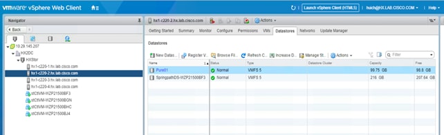
16. On the Datastores tab, select New Datastore to add the new storage volume to the Cisco HyperFlex cluster as a shared VMware Virtual Machine File System (VMFS) data store.
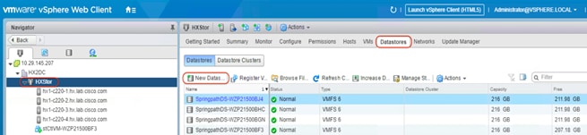
17. Review your data store on the Datastores tab for each host in the Cisco HyperFlex cluster and verify that this shared data store is accessible for all the Cisco HyperFlex hosts. Now you can migrate storage on any virtual machines or perform other storage operations as necessary. You can mount an existing VMFS data store on the external storage array and use Storage vMotion to move the existing virtual machines to the Cisco HyperFlex cluster too.
Expanding Cisco HyperFlex clusters with SAN-boot computing-only nodes
Cisco HyperFlex clusters that are composed of both converged nodes and computing-only nodes are built by first applying service profiles specific to Cisco HyperFlex to Cisco HyperFlex converged nodes, then installing ESXi, and then expanding the cluster with computing-only Cisco UCS nodes (which can be standalone Cisco UCS C-Series Rack Servers or Cisco UCS B-Series Blade Servers). The expansion of Cisco HyperFlex clusters is not supported with the Cisco Intersight platform at the time that this document was written. Therefore, the on-premises Cisco HyperFlex installer appliance must be used. The Cisco HyperFlex installer is distributed as a deployable virtual machine in the OVA file format through a downloadable ISO image from Cisco.com. The installer virtual machine has a wizard for cluster expansion.
Note: To add a node that uses a different CPU family than the one already in use in the Cisco HyperFlex cluster, the Enhanced vMotion Compatibility (EVC) mode must be enabled in vCenter before the expansion. For more details, see the Cisco HyperFlex Systems Installation Guide.
Before proceeding with the expansion process, the steps described earlier for creating the vHBAs, World Wide Name (WWN) pools, and SAN connectivity policy must have been completed, and these settings must have been applied to the compute-nodes or compute-nodes-m5 service profile templates, similar to the way the changes were applied to the Cisco HyperFlex converged node service profile templates.
To expand an existing Cisco HyperFlex cluster with a SAN-boot computing-only node, complete the following steps:
1. In Cisco UCS Manager, click the Servers tab in the navigation pane.
2. Expand Servers > Service Profile Templates > root > Sub-Organizations.
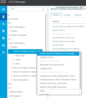
3. Select the suborganization for the Cisco HyperFlex cluster.
4. Right-click Service Profile Template compute-nodes (or compute-nodes-m5 for Cisco UCS M5 servers) and click Create Service Profiles from Template.
5. Enter the naming prefix of the service profiles that will be created from the template.
6. Enter the starting number of the service profiles being created and the number of service profiles to be created.
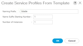
7. Click OK and then click OK again to complete the creation of the service profile.
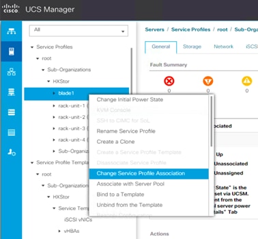
8. Expand Servers > Service Profiles > root > Sub-Organizations and select the appropriate Cisco HyperFlex suborganization.
9. Click the service profile you just created for the additional computing-only node (the Cisco UCS B200 M4 server in this configuration). Right click and choose Change Service Profile Association.
10. In the Server Assignment drop-down list, choose Select Existing Server.
11. In the list of available servers, choose the blade server to which you want to assign the service profile and then click OK.
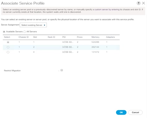
12. Click Yes to acknowledge that the server will reboot to apply the service profile.
13. Click OK. Wait until the overall status of the server becomes OK.
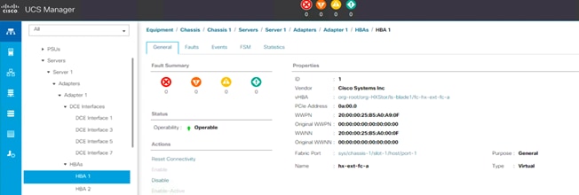
14. Verify that the vHBAs are created on this server for Fabrics A and B.
15. Follow the procedure described in the preceding section to configure the Cisco MDS switches properly.
16. Create a boot LUN on the storage disk array and then assign it to the blade server that will be expanded into the Cisco HyperFlex cluster as a computing-only node. Record the LUN ID; you will need it later to define the boot LUN in the Cisco UCS boot policy. Best practices normally prescribe that boot-from-SAN volumes and LUNs use ID 0 or 1 for ease of identification and consistency.
17. In Cisco UCS Manager, click the Servers tab in the navigation pane.
18. Expand Servers > Service Profiles > root > Sub-Organizations and select the appropriate Cisco HyperFlex suborganization.
19. Click the service profile for the computing-only blade server. Right-click and choose Unbind from the Template. Click OK to continue.
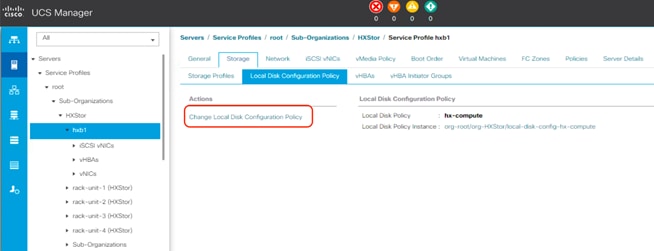
20. Click the service profile. On the Storage tab, click Local Disk Configuration Policy and select Change Local Disk Configuration Policy.
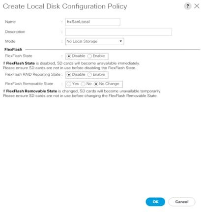
21. In the pop-up window, select Create Local Disk Configuration Policy.
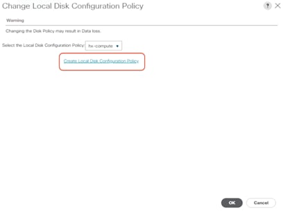
22. Enter the name of the new policy, select No Local Storage mode and leave FlexFlash state set as Disable. Click OK to create the new local disk configuration policy.
23. Now change the local disk configuration policy to the newly created policy for the SAN-boot server.
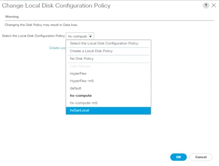
24. Click OK twice.
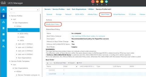
25. For the service profile, click the Boot Order tab and select Modify Boot Policy.
26. In the pop-up window, click Create Boot Policy.
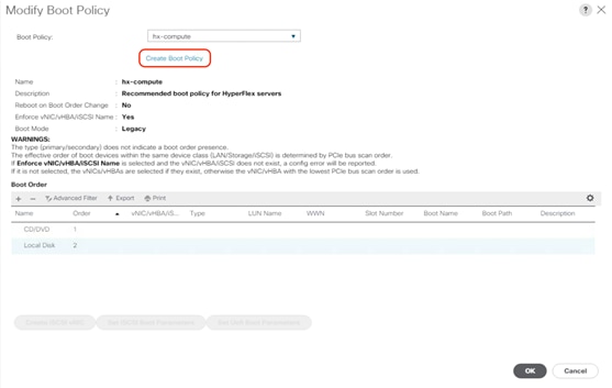
27. Create a new boot policy in the boot order including SAN boot configuration. For the SAN target devices, make sure that the WWPNs and LUN IDs are consistent with the values for the storage system.
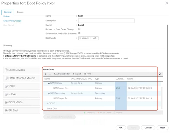
28. Click OK twice to return to the Modify Boot Policy page. Change the boot policy to the newly created SAN boot policy.
29. Click OK.
30. Click Yes to acknowledge that the server will reboot to apply the changes to the service profile.
31. In Cisco UCS Manager, launch the keyboard, video, and mouse (KVM) console for the blade server.
32. On the KVM console, choose Virtual Media > Activate Virtual Devices.
33. After the activate virtual devices process is completed, map the custom Cisco HyperFlex ESXi ISO image to the KVM CD/DVD device.
34. Reboot the server from the KVM-mapped virtual DVD (vDVD) device: that is, the custom Cisco HyperFlex ESXi ISO file. You will see a customized Cisco boot menu. In the Cisco customized boot menu, select Compute-Only Node – Install to Remote Disk (SAN) and then press Enter.
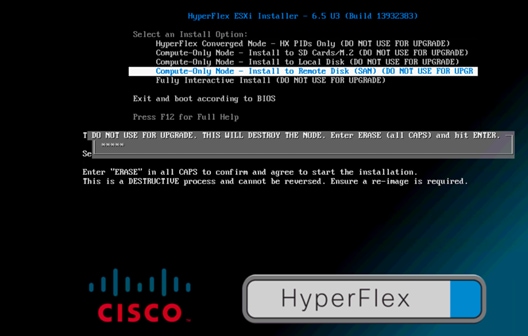
35. Enter ERASE and then press Enter. The ESXi installer will continue the installation process automatically. Wait until the installation is complete and the server boots successfully.
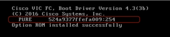
36. When the server reboots after installation of the ESXi operating system, verify that the server booted from a LUN on the remote storage array.
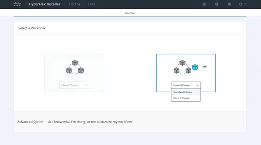
37. Now expand the existing Cisco HyperFlex cluster with this SAN-boot server. Open a web browser on the local computer and navigate to the IP address of the installer virtual machine. Log in to the Cisco HyperFlex installer appliance using the root account.
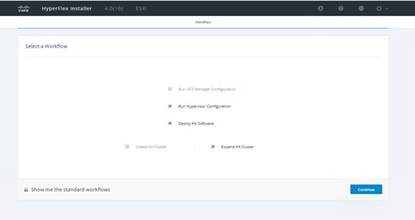
38. Select the workflow by choosing Standard Cluster from the drop-down Expand Cluster list.
39. Select the Run Hypervisor Configuration, Deploy HX Software, and Expand HX Cluster options. Click Continue.
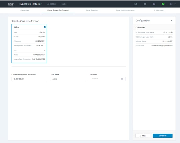
40. Enter the Cisco UCS Manager and VMware vCenter credentials and click Continue.
41. Verify that the cluster IP address is detected correctly, or enter the address manually. Enter the cluster access information and click Continue.
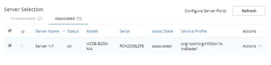
42. Select the associated blade server from the Server Selection list. Click Continue.
43. Enter the hypervisor settings and click Continue.
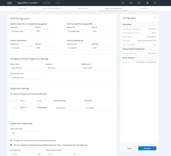
44. Add the IP address for the hypervisor management and data networks. Enter the controller virtual machine password. There are no storage controller IP addresses because this is a computing-only node.
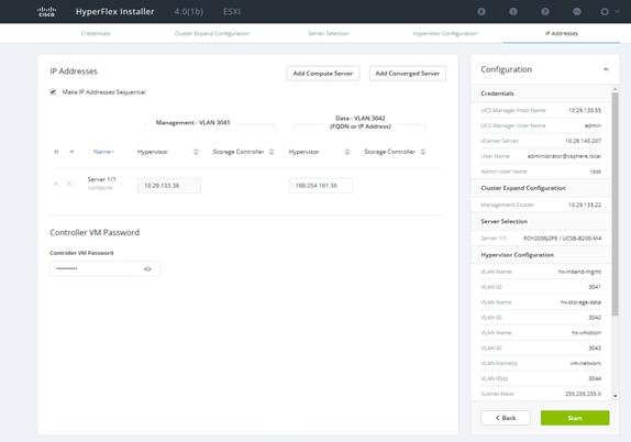
45. Click Start to start the cluster expansion process.
46. Review the summary screen upon completion of the Cisco HyperFlex cluster expansion.
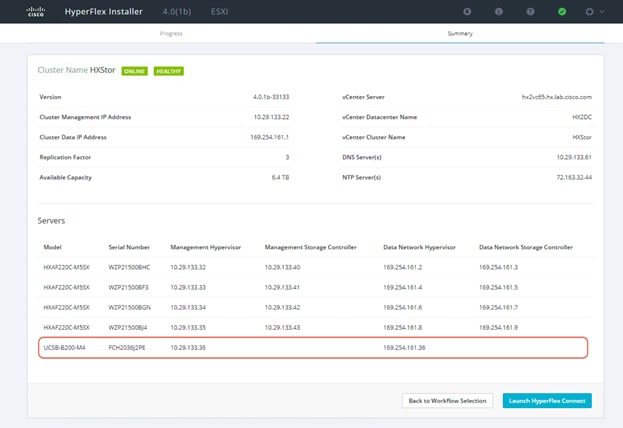
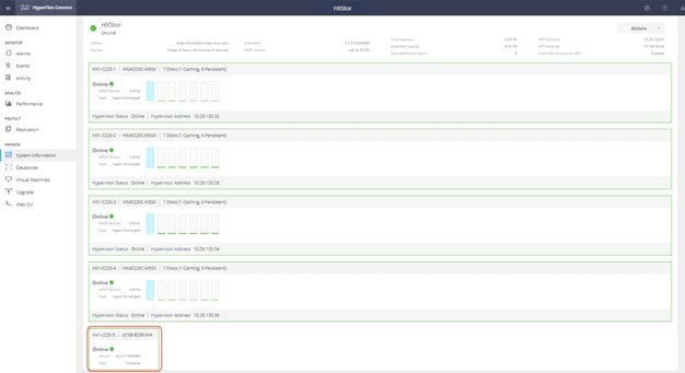
47. Launch Cisco HyperFlex Connect and verify that the status of Cisco HyperFlex cluster is Healthy. Click System Information and check the system status. Verify that the SAN-boot blade server has been added to the Cisco HyperFlex cluster as a computing-only node.
48. Before putting the expanded Cisco HyperFlex cluster into production, complete the necessary post-installation tasks.
In today’s rapidly evolving IT world, many organizations need to store tiered data using various storage technologies not only to protect their existing investments but also to meet government compliance requirements. A proven industry leader, Cisco provides converged infrastructure that integrates Cisco UCS servers, Cisco MDS SAN switches, and Fibre Channel storage systems from our partners. This integrated solution is offered in a validated design, accelerating the deployment and simplifying the management of the IT infrastructure for customers. Cisco HyperFlex systems provide optimized hyperconverged infrastructure for any workload at any scale. This solution provides an excellent choice of hardware and storage for the high-performing virtual infrastructure required for many new applications. The coexistence of Cisco HyperFlex systems with traditional SAN-based integrated systems gives customers the flexibility to choose how and where to allocate their data and provides a solid foundation for building a more robust, adaptive, and efficient IT environment.
For additional information, see the following:
● Cisco HyperFlex products, services, and solutions: https://www.cisco.com/go/hyperflex
● Cisco Fibre Channel SAN products, services, and solutions: https://www.cisco.com/site/us/en/products/networking/cloud-networking-switches/storage-area-networking/index.html
● Cisco Converged Infrastructure products, services, and solutions: https://www.cisco.com/site/us/en/solutions/computing/converged-infrastructure/index.html