Cisco UCS VIC 15000 Series Best Practices in Ethernet Fabric White Paper
Available Languages
Bias-Free Language
The documentation set for this product strives to use bias-free language. For the purposes of this documentation set, bias-free is defined as language that does not imply discrimination based on age, disability, gender, racial identity, ethnic identity, sexual orientation, socioeconomic status, and intersectionality. Exceptions may be present in the documentation due to language that is hardcoded in the user interfaces of the product software, language used based on RFP documentation, or language that is used by a referenced third-party product. Learn more about how Cisco is using Inclusive Language.
The Cisco Unified Computing System™ (Cisco UCS®) is a next-generation data-center platform that unites computing, networking, storage access, and virtualization resources into a cohesive system designed to reduce total cost of ownership (TCO) and increase business agility.
The fifth-generation Cisco UCS Virtual Interface Card 15000 series supports low-latency, lossless 10/25/40/50/100/200 Gigabit Ethernet and Fibre Channel over Ethernet speeds. Cisco UCS 15000 series virtual interface cards have next-generation converged network adapter technology, and a rich set of features for enterprise-class UCS X-Series compute nodes, B-Series blade servers, and C-Series rack servers.
The Cisco UCS Virtual Interface Card (VIC) incorporates Converged Network Adapter (CNA) technology and offers a comprehensive feature set, providing investment protection across multiple generations of UCS blade and rack servers.
Cisco UCS VIC 15000 Series adapters leverage the next generation of ASICs for UCS VIC product family. It enables a range of bandwidth options to choose from – 10/25/40/50/100/200 with latency ~1.0µs. It also enables PCIe Gen4 for high-speed data bus for data transfer, control and data-plane offloads, enhanced Quality of Service (QoS), and Precision Time Protocol (PTP), among a host of other features.
The Cisco UCS VIC 15000 Series is the fifth generation of VICs available in multiple form factors (15230, 15231, 15235, 15237,15238, 15411, 15420, 15422, 15425, 15427, and 15428) and speed (10/25/40/50/100/200 Gbps). For a comprehensive look into the supported features, please refer to the Cisco UCS VIC 15000 data sheet.
The audience for this document consists of system architects, system administrators, network administrators, and any other technical staff who are responsible for planning and maintaining the Cisco UCS infrastructure. Although every effort has been made to make this document appeal to the widest possible audience, the document assumes that readers understand Cisco UCS hardware, terminology, and its configuration management.
This document tries to address some of the frequently asked questions about the Cisco UCS VIC 15000 Series and the recommended practices from an Ethernet fabric perspective. The following topics are addressed in this document: bandwidth with VIC 15000 on blade and rack servers, UCS-X Series compute nodes, best-practices for adapter policies, overlay offloads, FEC settings, and various VIC connectivity considerations for rack servers.
Bandwidth on B-Series blade-servers
Cisco UCS B200 M6 Blade Server supports Cisco VIC 15411 dual-port 40G mLOM. There is no support for the Cisco UCS VIC 15000 Series mezzanine card form factor on Cisco UCS B-Series blade servers. The VIC 15411 also can work with an optional Port Expander (PE), which enables extra bandwidth on the VIC 15411 adapter.
Cisco UCS 5108 Blade Server Chassis has 32x10G-KR backplane Ethernet connections from each Cisco® I/O Module (IOM) toward the VIC cards on 8xB200 servers. This equates to 4x10G backplane traces per B200 server per IOM. These backplane traces originate from the Cisco VIC as uplink ports UIF0 (side A) / UIF1 (side B) and terminate on each IOM as a Host Interface (HIF).
The available bandwidth and throughput from B200 M6 servers depend on the IOM hardware version and the combination of Cisco VIC 15411 and port expander. vNICs and vHBAs created through service profiles get bonded to either 20G or 40G uplinks, depending on the presence of a port expander. In a single flow, vNIC/vHBA can achieve a bandwidth of 20G or 40G depending on the type of IOM and port expander installed.
The Figure 1 shows the connectivity on a UCS 5108 chassis with a Cisco UCS 2408 Fabric Extender connected to a Cisco UCS 6454 Fabric Interconnect (FI). The red lines are the 25Gbps physical connections from IOM to FI while the blue lines show the 10G-KR backplane connections from the IOM toward the VIC 15411 on a B200 M6 server.
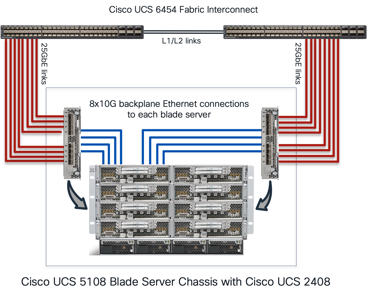
Cisco UCS 5108 Blade Server Chassis with FI 6454 and UCS 2408
The half-width blade server (B200 M6) on a UCS 5108 chassis can have the following combinations:
● mLOM (VIC 15411) installed on a blade server
● mLOM (VIC 15411) + Port Expander (PE)
● IOMs (2204/2208, 2304v1/v2, or 2408) on the chassis
● Fabric interconnects (FI 6332/6332-16UP series, FI 6454/64108 series, or FI 6536 series)
The Table 1 shows the throughput per B200 M6 server with 15411 and 15411 + PE combinations. The throughput from the server is calculated across both the fabric interconnects in the UCS domain.
Table 1. VIC 15411 throughput per B200 M6 blade server
| Adapter combination on B200 M6 |
FI 6536/6400 + IOM 2408 |
FI 6536/6300 + IOM 2304 |
FI 6400/6300 + IOM 2208 |
FI 6400/6300 + IOM 2204 |
| 15411 |
40G |
40G |
40G |
20G |
| 15411 + PE |
80G* |
80G* |
N/A |
N/A |
● FI 6400 series does not support IOM 2304.
● FI 6536 does not support IOM 2204 or 2208.
B200 M6, VIC 15411, port expander, IOM 2304 and 2308
On a B200 M6, VIC 15411 can have 20G or 40G vNICs. And the vNIC speed seen on the server depends on the VIC and port expander combinations installed on the blade server, as in the following:
● With 15411 alone on a B200 M6, the server will see 40Gbps (2x20) throughput with all IOMs except 2204. Without a port expander, vNIC on 15411 will only see a speed of 20G or 2x10G, and the vNIC will have an aggregate bandwidth of 20G with a maximum single-flow bandwidth of 20Gbps.
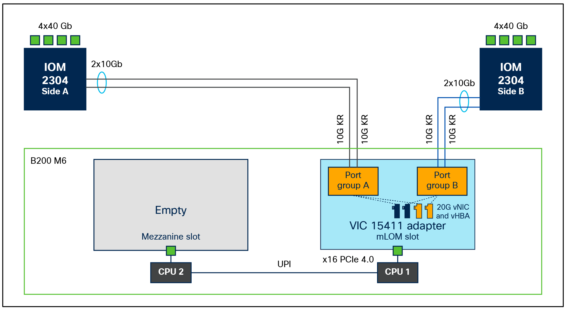
B200 M6 with VIC 15411 and IOM 2304
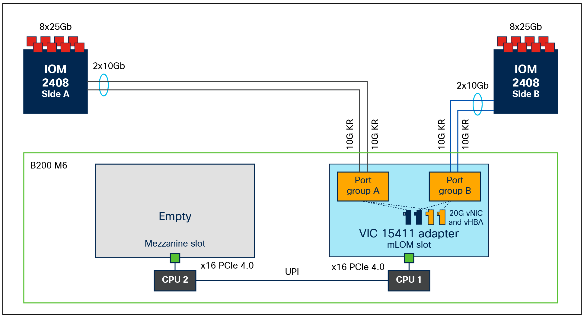
B200 M6 with VIC 15411 and IOM 2408
● 15411 with port expander on B200 M6 will enable a 40G KR4 interface toward IOM 2304 or IOM 2408. This enables a total of 80Gbps throughput per blade server. The servers, in this case, will see a vNIC bandwidth of 40Gbps, and each vNIC will support a maximum single flow of 40Gbps. Figures 4 and 5 depict the backplane connections that are enabled on a B200 M6 server with a VIC15411 and a port expander.
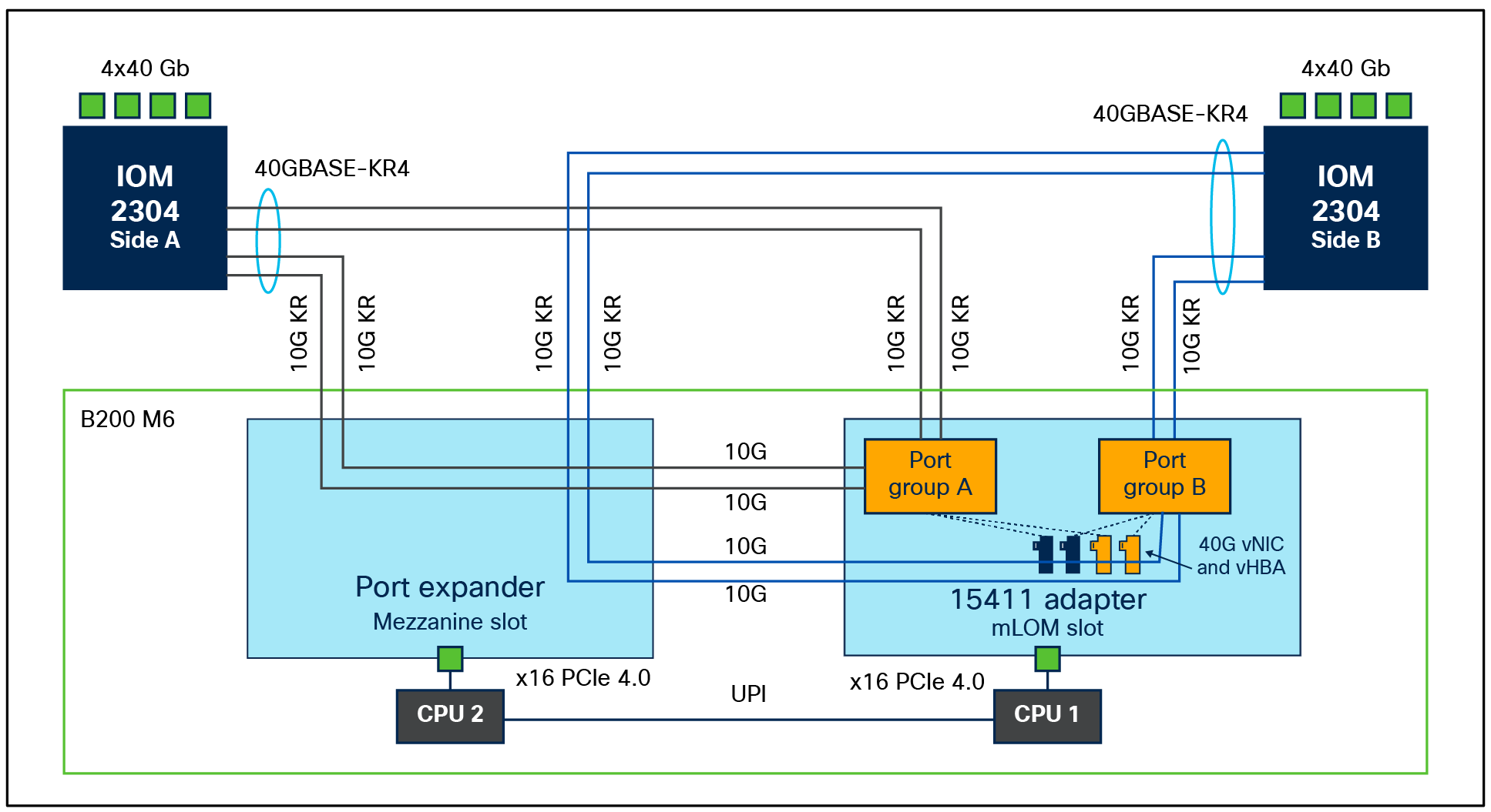
B200 M6 with VIC 15411 + port expander and IOM 2304
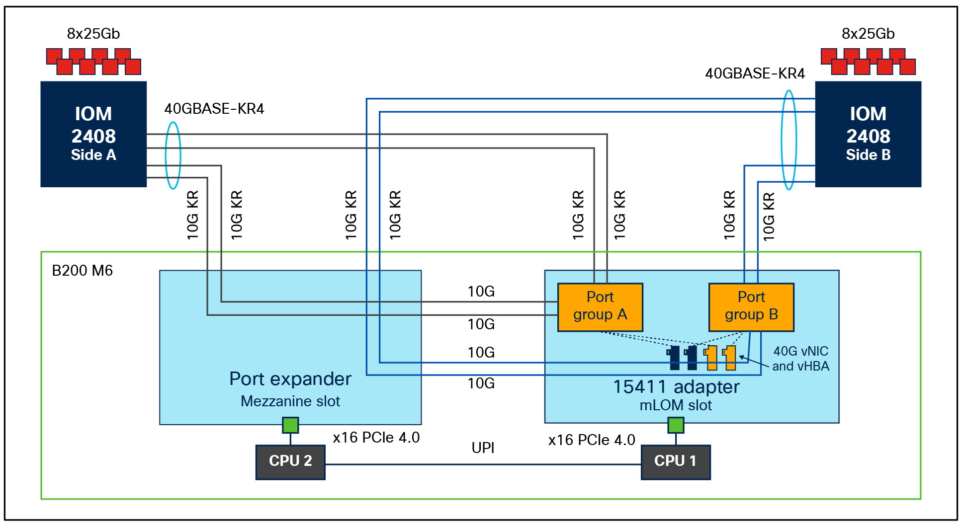
B200 M6 with VIC 15411 + port expander and IOM 2408
Please note that these are 40G-KR4 interfaces from the VIC 15411+PE toward the IOM 2304/2408 and not toward a 4x10Gbps hardware port channel.
Even though 40G-KR4 becomes enabled between a VIC 15411+PE and an IOM 2408, the connection to a FI 6400/6536 series from an IOM-2408 is through 25Gbps Ethernet links. And on the IOM, a single flow from the server/vNIC gets hashed to one of the IOM-2408 25Gbps ports; hence, each vNIC can achieve a maximum single-flow bandwidth of 25Gbps, even though the server-to-IOM connectivity is 40G KR4 or native 40Gbps. This may result in initial transient packet-drops due to the bandwidth mismatch.
Rate limit QoS policy: VIC 15000 with IOM 2408
To avoid initial transient packet drops for a flow on the IOM 2408 due to a bandwidth mismatch of 40Gbps from the server toward IOM 2408 and the 25Gbps Ethernet connection between IOM 2408 and FI 6400/6536, the vNICs can be rate limited to 25Gbps. The vNIC rate-limiting can be achieved through a QoS policy applied to the vNIC. Figure 6 shows such a policy and its application.
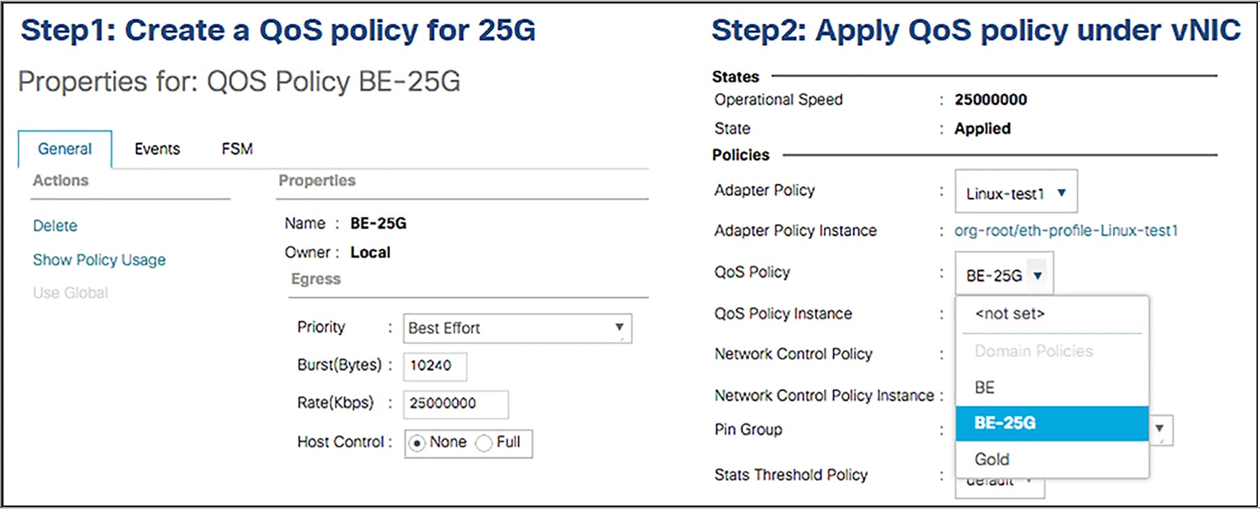
vNIC rate-limiting configuration in Cisco UCS Manager
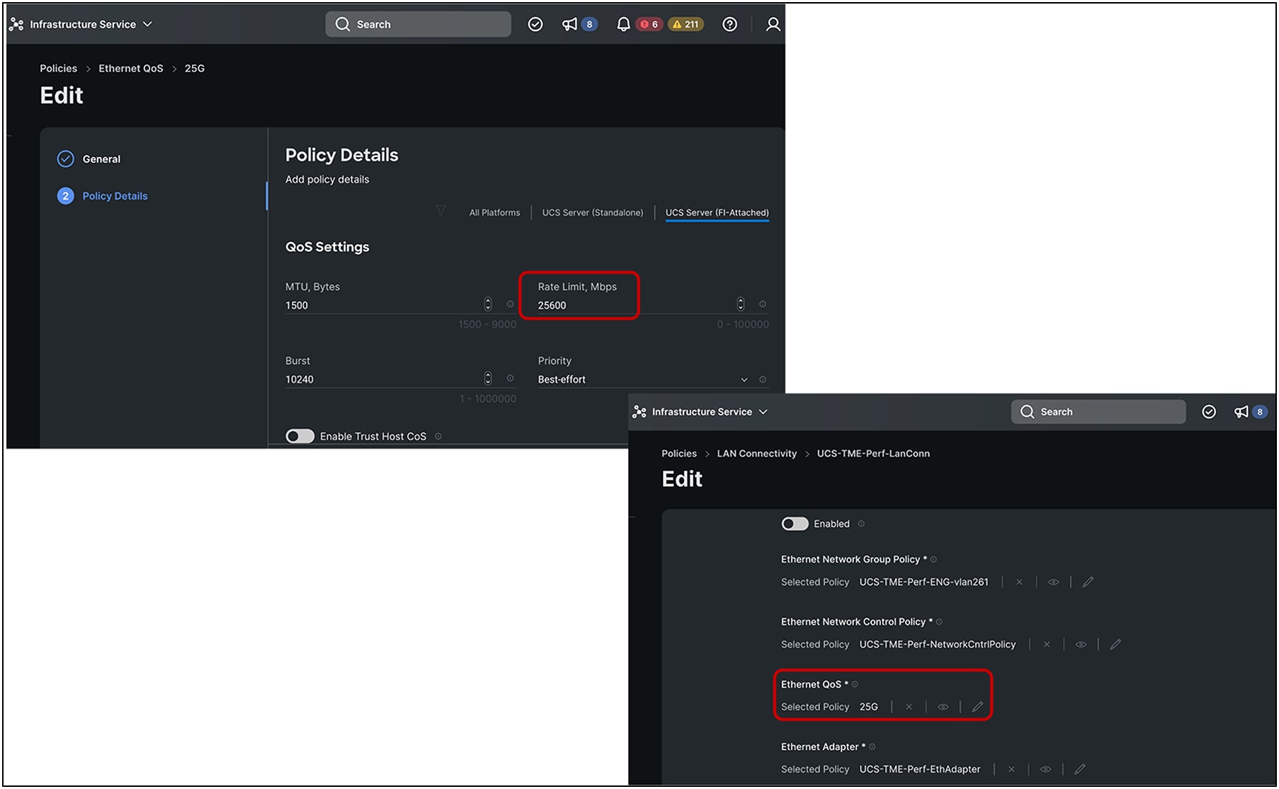
vNIC rate-limiting configuration in Cisco Intersight® Managed Mode
Bandwidth on Cisco UCS X-Series compute nodes
A Cisco UCS X210c Compute Node can have two VICs in mLOM and mezzanine form-factor and supports mLOM VIC 15230, 15231, 15420, and an optional VIC 15422 (mezzanine). The UCS X210c compute node with VIC 15230/15231 can provide 100G bandwidth to each side when installed with X9108-IFM-100G on a Cisco UCS X9508 Chassis. This results in cumulative bandwidth of 200G per X210c compute node. Similarly, mLOM 15420 and mezzanine 15422 on the UCS X210c compute node with either X9180-IFM-25G or X9180-IFM-100G can provide a cumulative bandwidth of 200G per compute node.
Note that on UCS X210c compute nodes, mixing 100G mLOMs (VIC15230/15231) with a mezzanine form factor VIC15422 is not supported.
Additionally, the X9508 chassis bandwidth is dependent on the intelligent Fabric Module (IFM) or fabric interconnect. The available options are:
● Intelligent Fabric Modules (IFMs): X9108-IFM-25G or X9108-IFM-100G
● Fabric Interconnects (FIs): UCS-FI-6536 or UCS-FI-6454/64108 (FI 6400 series)
The UCS X9508 chassis has a backplane-less design, which allows the chassis to provide newer and higher operating speeds on the server by swapping out the intelligent fabric modules in the chassis or the virtual interface card on the servers. An example is shown in Figure 8, where the chassis bandwidth can be quadrupled to 1600Gbps from 400Gbps by swapping out the IFM-25G with the latest IFM-100G.
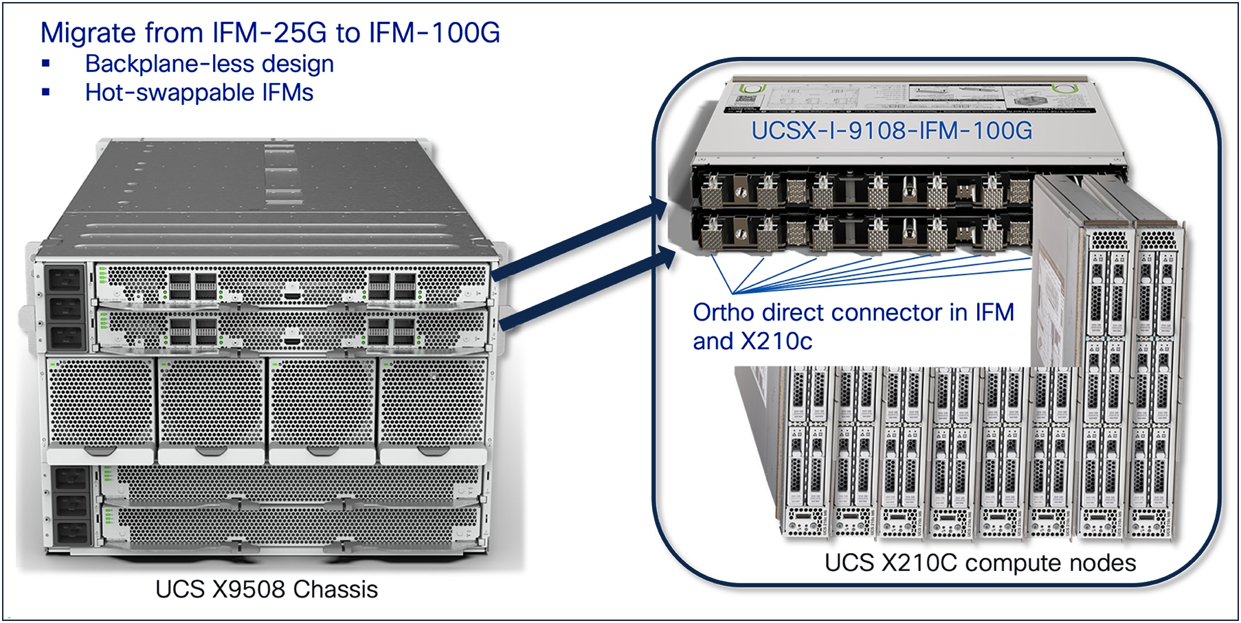
Cisco UCS X9508 Chassis, backplane-less design
In an X9508 chassis, each VIC 15420 and 15422 has 2x25G-KR lines to each IFM-25G or IFM-100G. Figure 9 shows the end-to-end connectivity from FI 6536 to the X210c compute nodes.
As shown in Figure 9, each X210c compute node has 8x25G-KR Ethernet connectivity to both the IFMs in a chassis, as represented by the red links. And the X9108-IFM-100G/25G will have 100G/25G Ethernet connectivity through physical cables to the Cisco UCS 6400-series/6536 fabric interconnect, represented by the blue links.
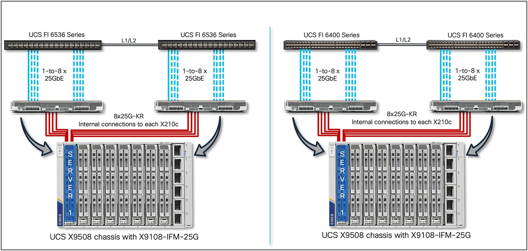
Cisco UCS X9508 Chassis, end-to-end connectivity with VIC 15420+15422
In the X210c compute node, with both VIC 15420 and 15422 installed, each VIC will have 4x25G-KR connectivity to both IFMs; also, having two VICs will enable 8x25G-KR Ethernet connectivity. Thus, across both VICs on the X210c compute node, there will be a total aggregate bandwidth of 200Gbps. Note that VIC 15422 is an optional mezzanine VIC that enables higher throughput, redundancy, and better CPU core utilization for server I/O.
Since each VIC will have 2x25G-KR connectivity to each IFM-100G/25G, the vNIC/vHBA that is provisioned on the VIC will have 50Gbps of bandwidth. So, an X210c compute node with VIC 15420 and 15422 will see 100G vNIC/vHBA on the ESXi/Linux/Windows OS. Figure 10 shows the vNIC/vHBA speed as seen on a Linux host.
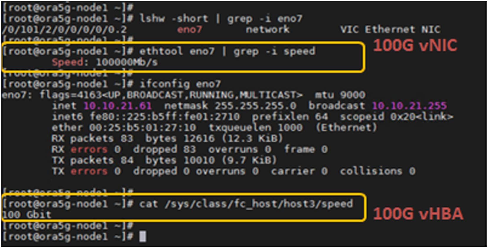
vNIC/vHBA speed seen by Linux OS with VIC 15420+15422
Table 2 shows a summary of the bandwidth, speed, and feeds possible with VIC 15000 series across various IFM and FI combinations. Note that FI-6536 supports both IFM-25G and IFM-100G while the FI-6400 series supports only IFM-25G.
Table 2. Cisco UCS X210c bandwidth options with Cisco UCS VIC 15000 series adapters
| Cisco UCS X210c Compute Node |
A Fl-6536 + X9108-IFM-100G |
B Fl-6536/6400-Series + X9108-IFM-25G |
C Fl-6536 + X9108-IFM-25G/100G or Fl-6400-Series + X9108-IFM-25G |
D Fl-6536 + X9108-IFM- 25G/100G or Fl-6400-Series + X9108-IFM-25G |
|
| x210c configuration |
VIC 15231 |
VIC 15231 |
VIC 15420 |
VIC 15420 + VIC 15422 |
|
| Throughput per node |
200G (100G per IFM) |
100G (50G per IFM) |
100G (50G per IFM) |
200G (100G per IFM) |
|
| vNICs needed for max BW |
2 |
2 |
2 |
4 |
|
| KR connectivity per IFM |
lx 100GKR |
2x 25GKR |
2x 25GKR |
4x 25GKR |
|
| Single vNIC throughput on VIC |
100G |
50G (2x25G KR) |
50G (2x25G KR) |
50G (2x25G KR) |
50G (2x25G KR) |
| Maximum single flow BW per vNIC |
100G |
25G |
25G |
25G |
25G |
| Single vHBA throughput on VIC |
100G |
50G |
50G |
50G |
50G |
Figures 11 through 14 are representations of the internal connectivity from the IFM to the X210c compute node with VIC 15231/15230, VIC 15420, and VIC 15420+15422 combo. These figures show the 25G-KR connectivity from IFM to VIC and the dynamically provisioned vNIC/vHBA, the Ethernet NIC or FC HBA interfaces for the operating system, on the VIC.
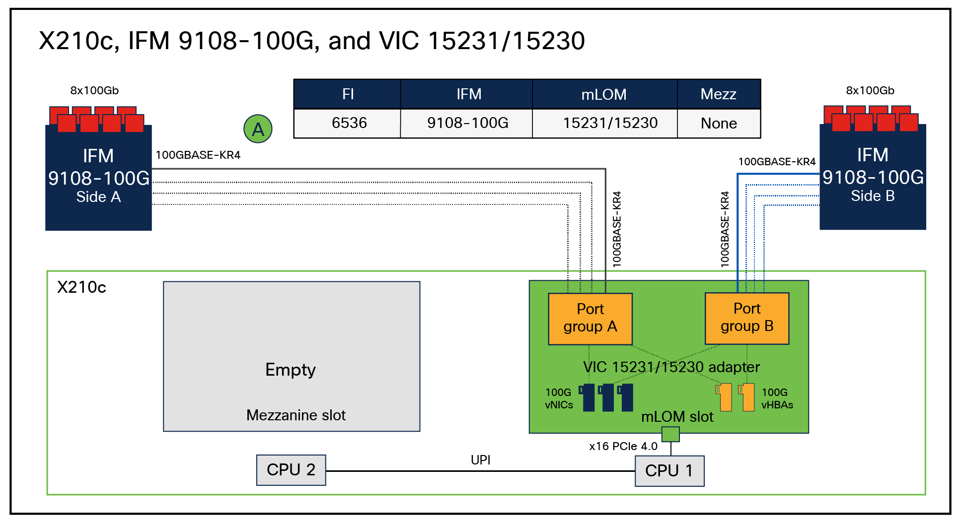
vNIC/vHBA internal connectivity between VIC 15231/15230 and 100G IFM
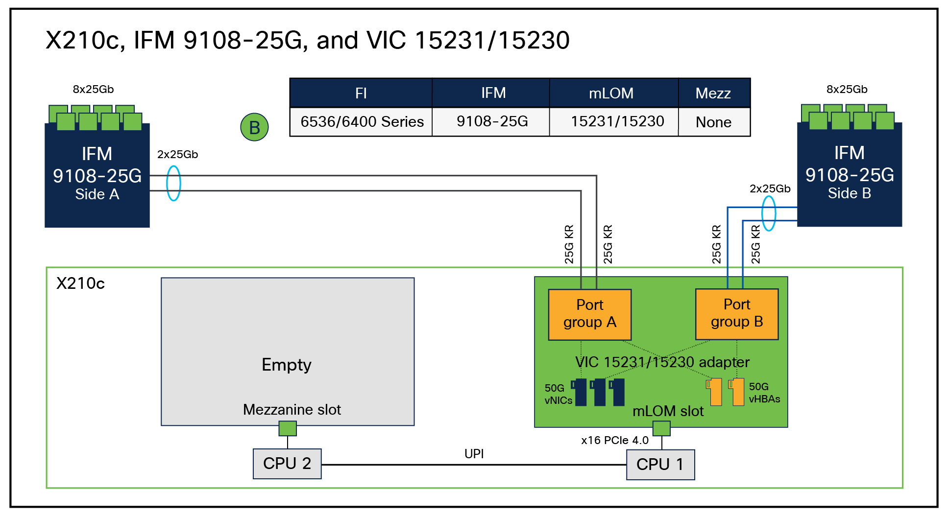
vNIC/vHBA internal connectivity between VIC 15231/15230 and 25G IFM
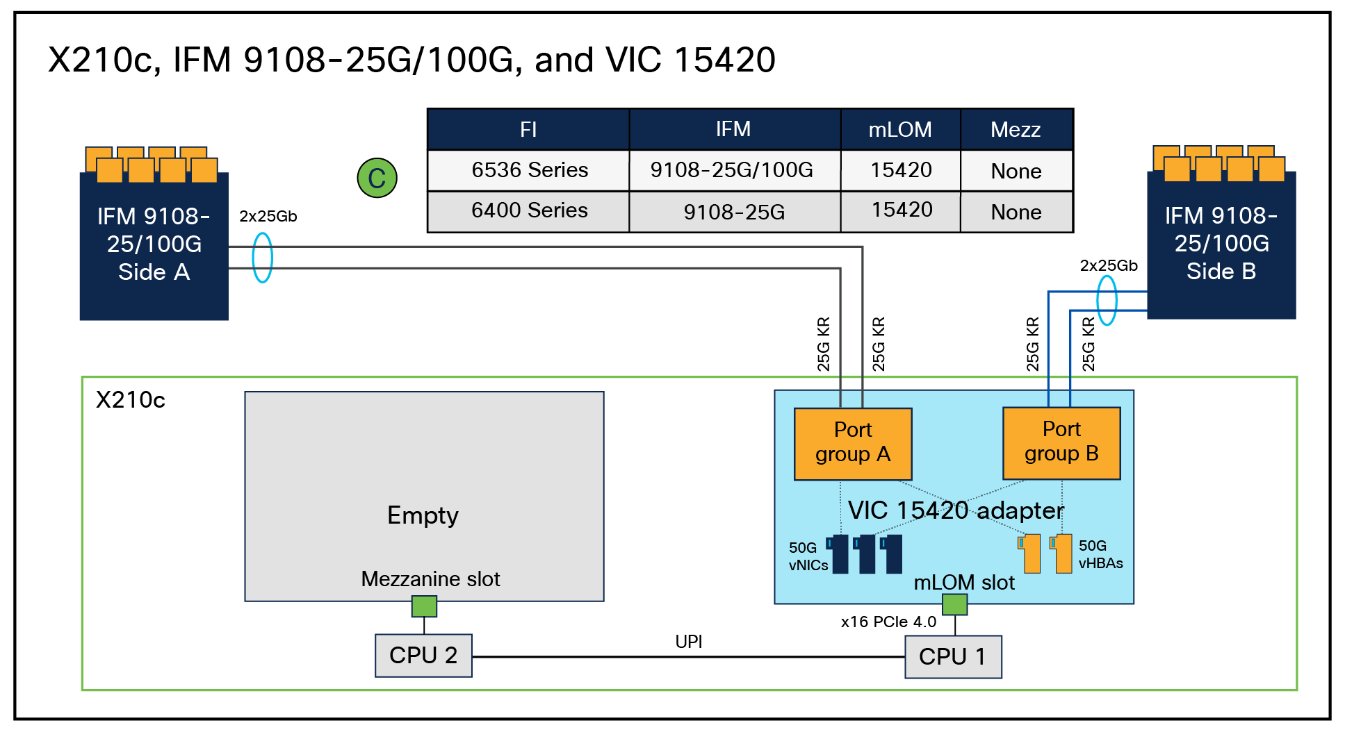
vNIC/vHBA internal connectivity between VIC 15420 and 25G/100G IFMs
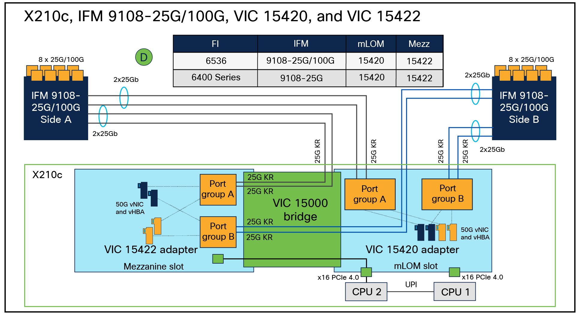
vNIC/vHBA internal connectivity between VIC 15420+15422 and 25G/100G IFMs
Performance tuning for Cisco UCS VIC 15000 Series adapters
Performance tuning of a Cisco UCS server involves: BIOS policy tuning, VIC adapter tuning, and OS tuning.
BIOS policy tuning for UCS servers is detailed in the white paper “Performance Tuning Best Practices Guide for Cisco UCS M7 Servers.”[1]
OS tuning is not something specific to UCS servers, and you should follow the best practices for the OS you are using. The focus of this section is to provide VIC-tuning recommendations for achieving maximum performance from Cisco UCS VIC 15000 adapters.
The focus will be primarily on the following VIC 15000 features and recommendations to maximize performance:
● Enhanced ring-size buffer allocation
● VIC adapter policy with RSS for Linux, Windows, and ESXi
● RSSv2 for Windows
● NetQueue support for ESXi
● Virtual Machine Multiple Queues (VMMQ) support for Windows
● Single-Root I/O Virtualization (SR-IOV) support for Linux and ESXi
● NetFlow support
● Maximum Transmission Unit (MTU) settings
● Overlay offload
In Cisco UCSM and IMM, there are predefined adapter policies available based on the application and OS. The default Ethernet adapter-policies on UCSM/IMM for the various operating systems with VIC 15000 based on specific feature support are as follows:
● Ethernet adapter-policy “Linux” for Linux, “Windows” for Windows and “VMWare” for ESXi environments
● Ethernet adapter-policy “Linux-NVMe-RoCE” for Linux supporting RoCEv2
● Ethernet adapter-policy “SR-IOV-HPN” (single-root I/O virtualization high-performance networking)
● Ethernet adapter-policy “MQ-SMBd” for Windows SMB Direct with RoCEv2 Mode 2
● Ethernet adapter-policy “Win-HPN” for Windows VMMQ support
● Ethernet adapter-policy “Win-HPN-SMBd” for Windows SMB Direct with RoCEv2 Mode 1
The default adapter policies across operating systems and workloads are good enough for the majority of UCS server deployments. But at the same time, depending on applications and server needs, you will have to modify or define new adapter policy.
These adapter-policy recommendations are independent of the Cisco Validated Design (CVD) recommendations for the various UCS solutions. The CVD recommendations should be followed when deploying the corresponding CVD solutions. Also, please note that, depending on the application, multiple TX/RX queues could be defined differently from the values given in the table, and these adapter-policy recommendations are for the VIC 15000 series.
VIC 15000 series adapters support Receive-Side Scaling (RSS), Virtual Machine Queue (VMQ), Virtual Machine Multiple Queues (VMMQ), RSSv2 for Windows, and SR-IOV for both Linux and ESXi. The following sections will cover nuances of each of these features that are specific to VIC 15000, and customers can deploy any of these solutions based on their application requirements.
With Cisco UCSM/IMM Release 4.3(4a), new optimized adapter policies are available for Windows, Linux, and VMware operating systems. These policies are optimized for performance with Cisco UCS VIC 15000 Series adapters. They have fine-tuned adapter parameters set as the defaults under resources and configuration options, as applicable. These adapter settings are recommended for VIC 15000 series and are optimized for high-performance networking on Linux, VMware, and Windows operating environments. Below is the list of new adapter policies for various operating systems with the VIC 15000 series:
● Ethernet adapter-policy “Linux-v2” and “VMWare-v2” - recommended adapter settings for VIC 15000 series and optimized for Linux and VMWare high-performance networking
● Ethernet adapter-policy “MQ-v2” - recommended adapter settings for VIC 15000 series and optimized for virtual machine multiple queues high-performance networking
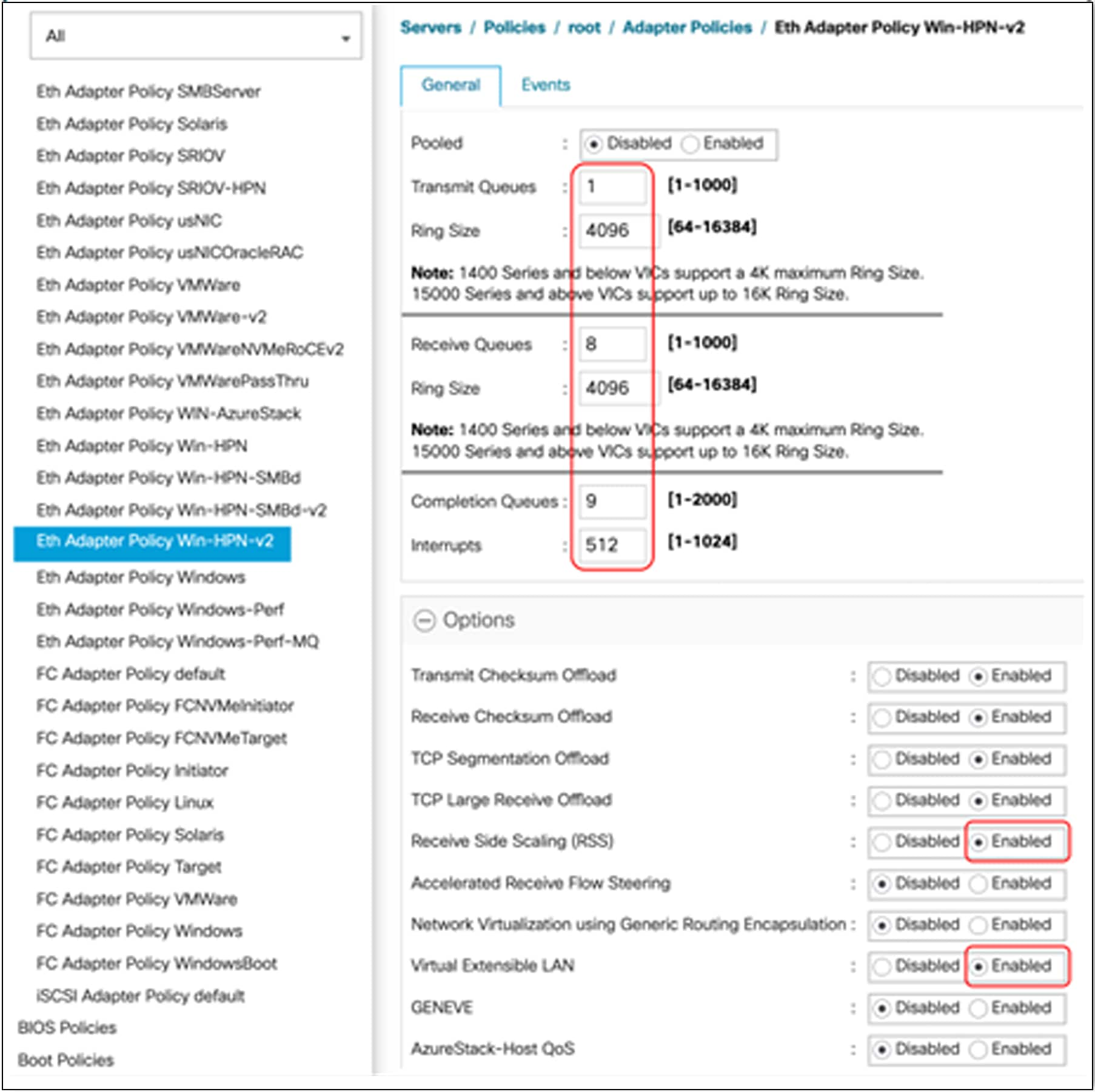
● Ethernet adapter-policy “Win-HPN-v2” - recommended adapter settings for VIC 15000 series and optimized for Windows high-performance networking for Windows VMMQ support
● Ethernet adapter-policy “Win-HPN-SMBd-v2” - recommended adapter settings for VIC 15000 series and optimized for Windows SMBd high performance networking for Windows SMB Direct.
● Ethernet adapter-policy “MQ-SMBd-v2” – recommended adapter settings for VIC 15000 series for Windows with RoCEv2 Mode 2 support
Enhanced ring-size buffer allocation
Cisco UCS VIC 15000 Series adapters now support up to a ring size of 16K (specifically, 16,384). This enables a higher number of packet descriptors that can be stored in the memory reserved for the adapter before they are processed by the host system’s CPU. This applies to both “receive” and “transmit” queues. Having a 16K ring size buffer offers several advantages:
● Reduced CPU usage: A larger ring size allows the adapter to buffer more incoming packets before requiring CPU attention. This reduces the frequency of interrupt calls to the CPU, which results in lower overall CPU utilization and improves system performance.
● Improved network throughput: with a larger ring size, the adapter can efficiently handle a higher volume of network traffic without overwhelming the CPU, resulting in lower latency and better throughput.
● Buffering for “bursty” traffic: Larger ring sizes are particularly beneficial for handling “bursty” traffic patterns, where packets arrive in quick succession. Adapter can buffer these packets in the ring, preventing packet drops and ensuring consistent performance.
A larger network adapter ring size can be advantageous for high-performance networking. It should be chosen based on available system resources and type of network workload.
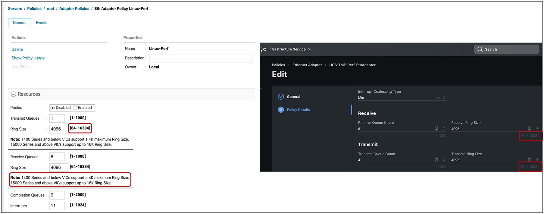
Enhanced ring-size buffer configuration options for Cisco UCS VIC 15000 Series in UCSM/IMM
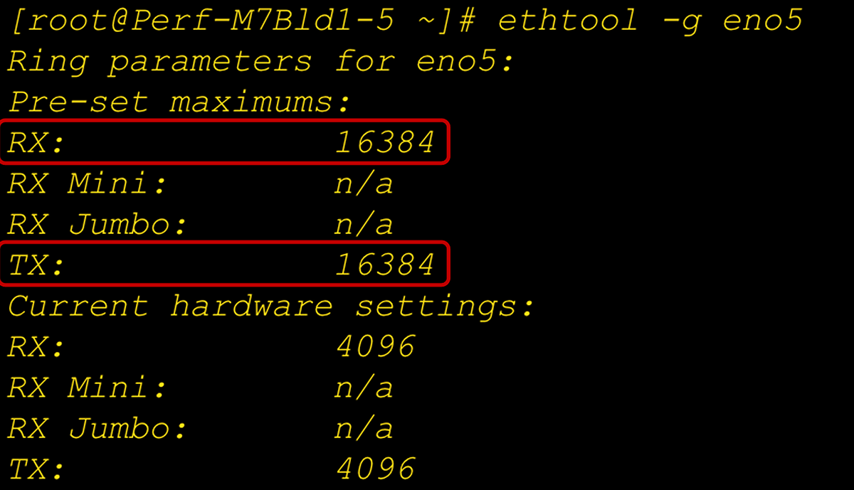
Enhanced ring-size buffer setting at the adapter and OS level
Receive-side scaling, or RSS, is a VIC hardware feature that allows for distributing traffic across multiple RX queues on the adapter and thus enable receive queues getting processed across multiple CPU cores by the host operating system. Having traffic spread across multiple RX queues and processed by different CPU cores helps in driving higher network throughput. It results in better CPU utilization and minimizing CPU hogging.
RSS improves network performance by reducing:
● Processing delays by distributing network receive processing over multiple CPUs. This helps in optimizing load on CPU cores.
● Spinlock overhead by increasing the probability of shared data execution on multiple CPU cores. For example, spinlock overhead occurs when a function executing on a CPU0 possesses spin lock on data that a function running on CPU1 must access; thereby, CPU1 spins (waits) until CPU0 releases the lock.
Having an adapter policy with RSS enables VIC hardware solution, in which packets are load balanced across multiple RX queues based on the packets’ Layer-2, Layer-3, and Layer-4 headers. This is an optimized solution for improving performance in bare-metal (Windows, Linux) and hypervisor (ESXi, KVM) environments.
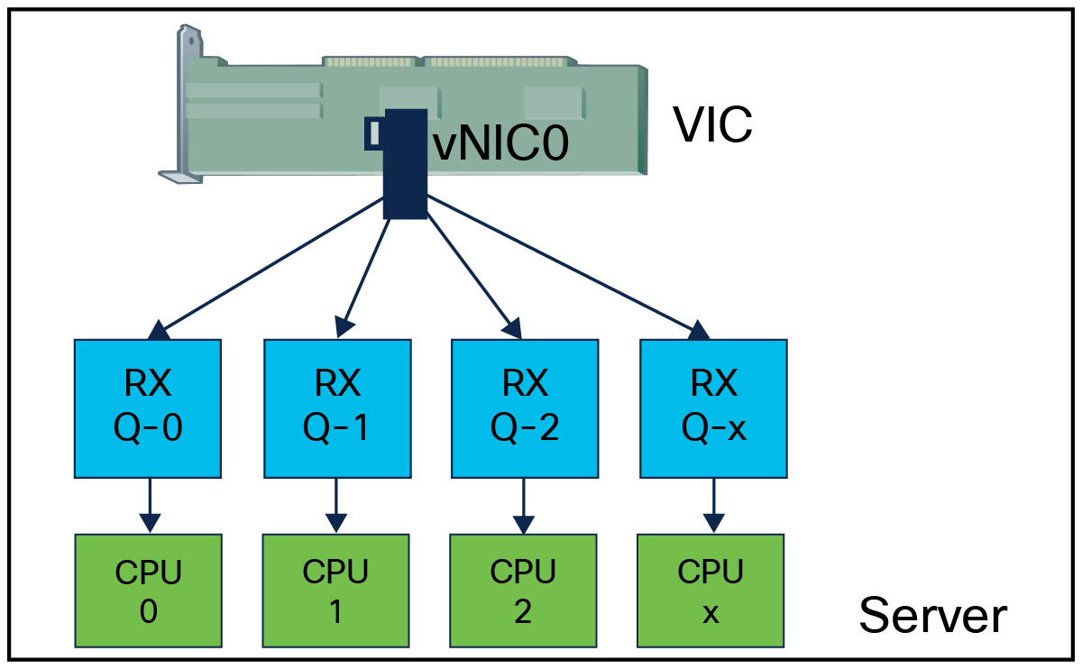
Receive queues mapping to CPU cores with RSS enablement
Along with the higher number of RX queues and RSS, another important performance improvement consideration is to increase the ring size per queue on the VIC adapter. Increasing the ring size allows more packet buffer per queue, thus preventing packet drops and retransmissions.
All the configuration parameters – TX/RX queues, ring size, and feature RSS – are activated through the adapter policy attached to a vNIC and deployed through server profile on server using either Cisco UCS Manager or Cisco Intersight. Same can be done through the vNIC properties in the Cisco Integrated Management Controller (IMC) for a standalone rack server.
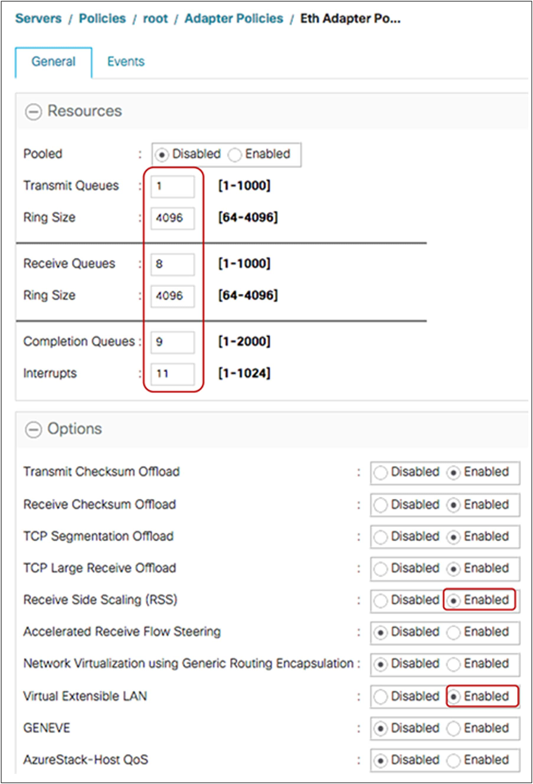
Table 3 presents adapter policy recommendations in terms of TX/RX queues and RSS that address the majority of higher throughput and performance requirements.
Table 3. Recommended adapter policy for the best performance with RSS*
| Parameter |
ESXi |
Linux |
Windows |
| TX queue |
1 |
1 |
1 |
| TX ring size |
4096 |
4096 |
4096 |
| RX queue |
8 |
8 |
8 |
| RX ring size |
4096 |
4096 |
4096 |
| CQ |
9 |
9 |
9 |
| Interrupt |
11(CQ + 2) |
10 or 11(CQ + 2) |
512 or “2 x CPU-cores + 4”* |
| RSS |
Enabled |
Enabled |
Enabled |
Note: With Cisco UCSM/IMM release 4.3(4a), these recommended adapter configuration parameters have now been built into new system provided adapter policies, suffixed with “-v2” for the VMWare, Linux and Windows operating systems that use VIC 15000 adapters. Users can now directly apply these policies without a need to create user-defined policies with configuration parameters taken from the table above.
The completion Queue (CQ) is “RX + TX” for all operating systems. Included below are some of the adapter-policy recommendations for ESXi, Linux, and Windows OS with multiple TX/RX queues and RSS.
ESXi
Cisco UCS VIC 15000 adapter-policy considerations for the VIC RSS feature with ESXi are the following:
● The maximum number of RX queues is 16 for most ESXi versions (the exception is ESXi 6.0, which supports up to 8 RX queues).
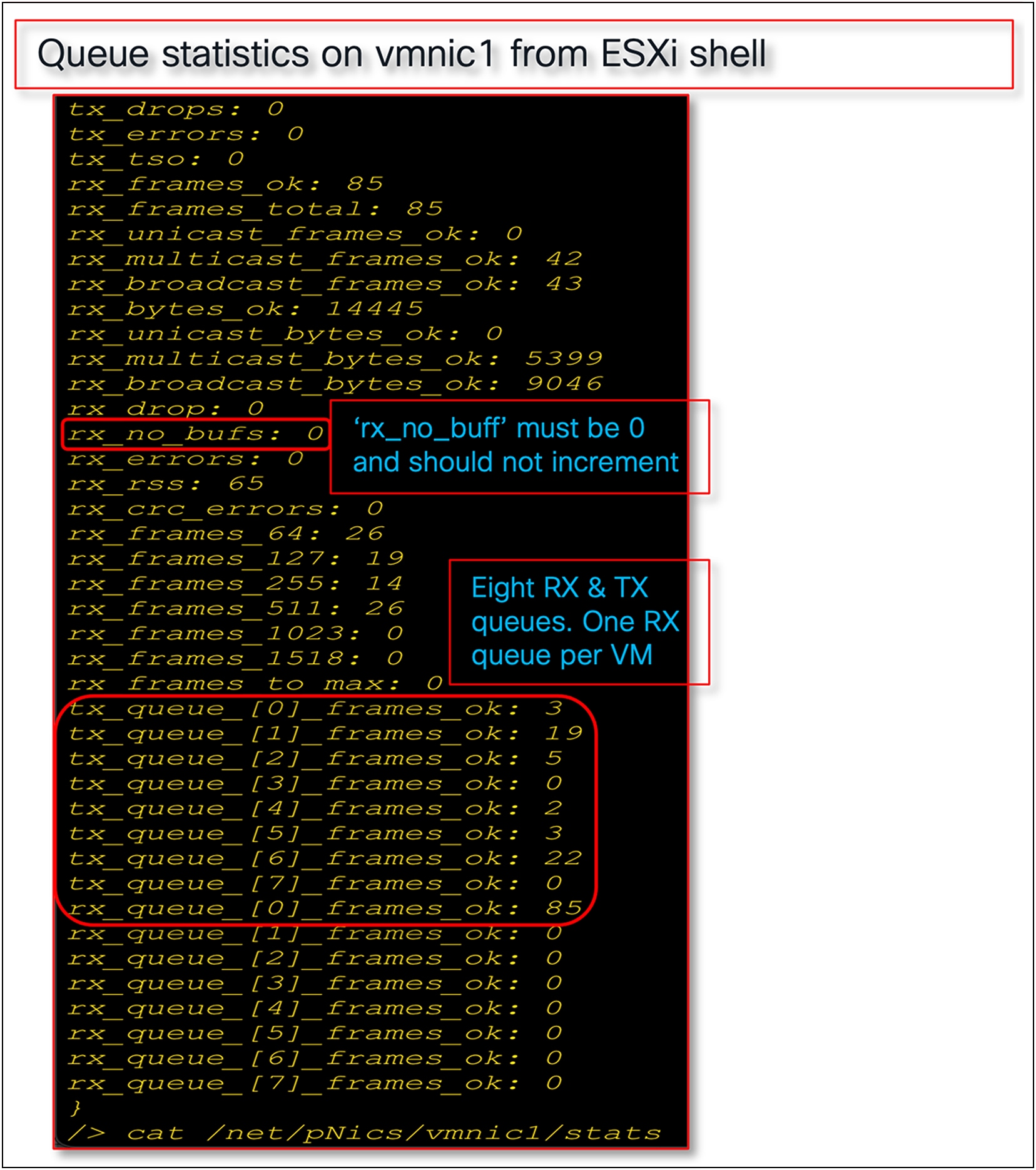
● Having a ring size of 4096 for TX/RX queues allows for more packet buffering; it helps in overall throughput and having lower retransmissions. We can set the ring size up to a maximum supported value of 16,000.
● If the pNIC/VMNIC statistics in the ESXi host show “rx_no_bufs” as incrementing, this indicates slower processing of packets by the ESXi host; the recommended fix is to increase the RX queues or the RX ring-size, or a combination of both, on the vNIC adapter policy.
Figure 18 shows an adapter-policy with RSS that is applied on a vNIC from UCSM and the corresponding VMNIC interface statistics for an ESXi host.
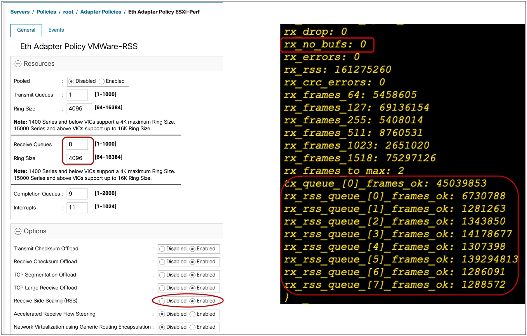
Adapter policy in UCSM with RSS for ESXi host
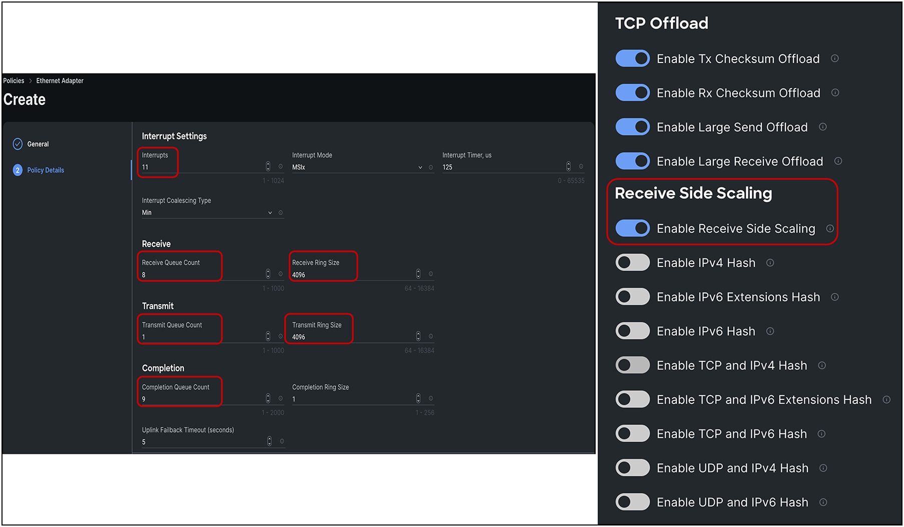
Adapter policy in Intersight with RSS for ESXi host
Linux
For Linux, the following are the considerations for the VIC 15000 RSS feature depending on the eNIC driver version:
Linux eNIC drivers prior to 3.2 release:
● Supports a maximum of 8 TX and 8 RX queues with RSS.
● Completion Queues (CQ) are the sum of Transmit Queues (TX) + Receive Queues (RX).
● The interrupt calculation for these eNIC drivers is “CQ + 2 rounded up to nearest power of 2”.
◦ For example, if TX = 1 and RX = 8, then CQ = 9 (TX + RX), that will make Interrupt count =
16 {(CQ + 2) rounded up to the nearest power of 2}.
Linux eNIC driver 3.2 and later releases:
● Supports interrupt sharing for RX/TX queues allowing greater than 8 RX and 8 TX queues.
● Supports up to 256 RX and TX queues, but it is recommended that they not be configured with more than the number of CPU cores that the server has.
● Completion queues would be transmit queues + receive queues (“TX+RX”).
● Interrupt calculation would be “Larger of (RX,TX) + 2”.
◦ For example, for TX = 4, RX = 8, and CQ = 12(TX + RX), the interrupt would be 10.
● Increasing the ring size to 4096 for handling packet drops due to slower processing by the host OS is also applicable to Linux drivers.
● Depending on application workload requirements, both the TX/RX queues and the ring size can be increased.
Windows
The following are the considerations for the Windows adapter-policy with RSS on VIC 15000:
● vNIC with RSS is recommended for Windows bare-metal servers. It is recommended to use the predefined adapter policy, as available in Cisco UCS Manager and Cisco Intersight, “Win-HPN” for regular RSS vNICs on Windows OS.
● While vNIC with RSS can be used for a Microsoft Hyper-V host, the recommendation is to use the Virtual Machine Multiple Queues (VMMQ) feature; configuration details are described in a later section.
● If RDMA is required, it is recommended to use the predefined “Win-HPN-SMBd” adapter policy for RoCEv2 mode 1 support over Physical Function (PF).
● Recommended default adapter policy for RoCEv2 mode 2 is “MQ-SMBd.” (Note: Mode 2 is inclusive of Mode 1; Mode 1 must be enabled to operate Mode 2.)
● Depending on the application performance needs; higher throughput and better CPU utilization can be achieved using a custom adapter-policy with 8 RX queues and a ring size configured to a maximum of 4096.
● The maximum number of RX queues possible for a Windows adapter policy is 8; the number of TX queues cannot be more than one.
● Example values for the adapter policy with maximum values are as follows:
◦ TX queue = 1, TX ring size = 4096
◦ RX queue = 8, RX ring size = 4096
◦ CQ = 9, interrupt = 512 (Note that the minimum interrupt should be “2 x CPU Core + 4”; see the next bullet entry.).
◦ Enable RSS
● The minimum interrupt recommended for VIC 15000 is “2 x CPU core + 4.” For example, for a dual-socket B200 M5 with Intel® Xeon® Gold 6142 having 16 cores, the minimum interrupt would be “(2x(2x16) + 4)” or 68, set by the user. Internally, though VIC firmware will configure an interrupt number rounded to the nearest power of 2, which, in this example, would be 128.
● If a generic interrupt value is needed across servers, an interrupt value of 512 can be configured in the adapter policy and assigned to vNICs.
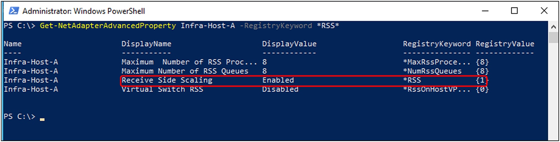
RSS feature enablement as shown in the Windows host operating system
Receive-side scaling, version 2 (RSSv2)
In the first generation of RSS, the network adapter distributes incoming packets among the receive queues based on the hash value calculated over certain fields of the packet header (such as IP addresses and port numbers). RSSv2 enhances the previous version by introducing a more sophisticated way of distributing the incoming network traffic. Rather than just relying on the packet header fields, RSSv2 also considers the packet payload. It uses a consistent hash function over the packet payload to distribute traffic, which can significantly improve the load balancing among the processors. It also introduces the concept of "flows," where a flow is a sequence of packets from a single conversation, which helps to maintain the order of packets.
RSSv2 is the second generation of receive-side scaling mechanism supported on Windows 2019 and later, beginning with Cisco UCS Manager Release 4.3(2a) and IMM. It requires supported Windows NENIC driver to be installed on the host windows operating system. RSSv2 is compatible with RSS. In general, a NENIC driver supports up to 8 queues. With RSSv2 the driver has no upper limit on the number of VIC hardware queues for Physical Function (PF) or VM, but the operating system does have an upper limit on the supported number of queues. With RSSv2 enabled on the Windows NENIC driver and Cisco UCS VIC adapter, you can configure multiple hardware receive queues on the Physical Function (PF). With VMMQ enabled on the VIC, you can configure multiple hardware receive queues per VM.
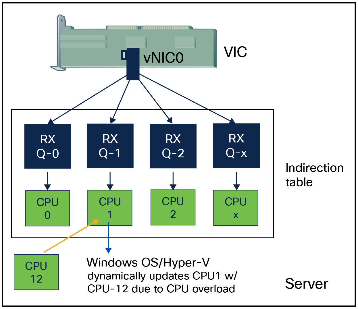
RSSv2 is an extension of RSS; it is a driver feature only. All it requires from Cisco VIC is support for RSS and VMMQ. It offers a dynamic spreading of network receive queues per vPort. RSSv2 allows moving one or more indirection-table entries from one CPU to another CPU while traffic is flowing, where an indirection table is an array consisting of CPU cores to Receive Queues (RQs) mappings. It also measures CPU load and updates indirection table entries. These capabilities of RSSv2 make it dynamic for load-balancing Receive Queues (RQs) across CPU cores during run times.
Dynamic receive queues mapping to CPU cores with RSSv2
RSSv2 is commonly used in high-performance network scenarios, such as cloud computing, online gaming, real-time video streaming, etc. It can greatly improve network performance by effectively utilizing multicore processors.
RSSv2 is compatible with the following features:
● Remote Direct Memory Access (RDMA)
● Virtual Machine Multiple Queues (VMMQ)
● Virtual extensible LAN (VXLAN)
● Network Virtualization Using Generic Routing Encapsulation (NVGRE)
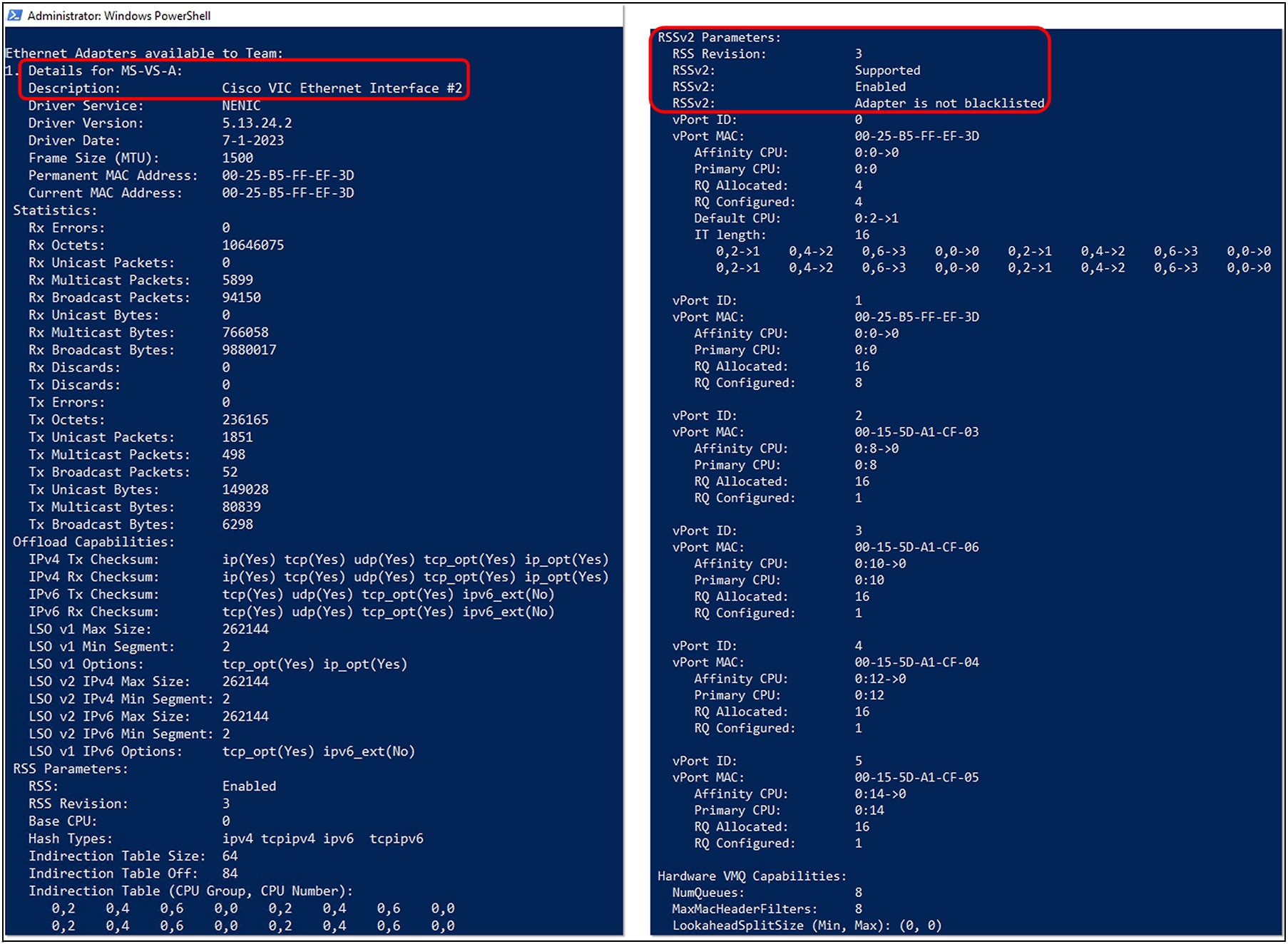
To note here again, RSSv2 is a Windows NENIC driver feature supported by Cisco VIC. With the supporting driver installed on the host operating system, we can verify its enablement as shown in Figure 22. Figure 22 shows RSSv2 support on a Physical Function(PF)/interface without virtual switch(vSwitch) configured.
RSSv2 feature enablement as shown in the Windows host OS
To verify RSSv2 enablement on a virtual switch (vSwitch), a vNIC associated with the virtual switch should have a VMQ-connection policy applied. Details on VMQ policy and its application is covered in the ‘VMMQ with Windows’ section. Other than this, the network adapter used in the virtual switch configured on the Windows hypervisor host should have the advance property “Receive Side Scaling” set to enabled. Other RSS properties, such as the maximum number of RSS queues, are configured through the adapter policy used in the service profile applied to the Windows hypervisor host server.
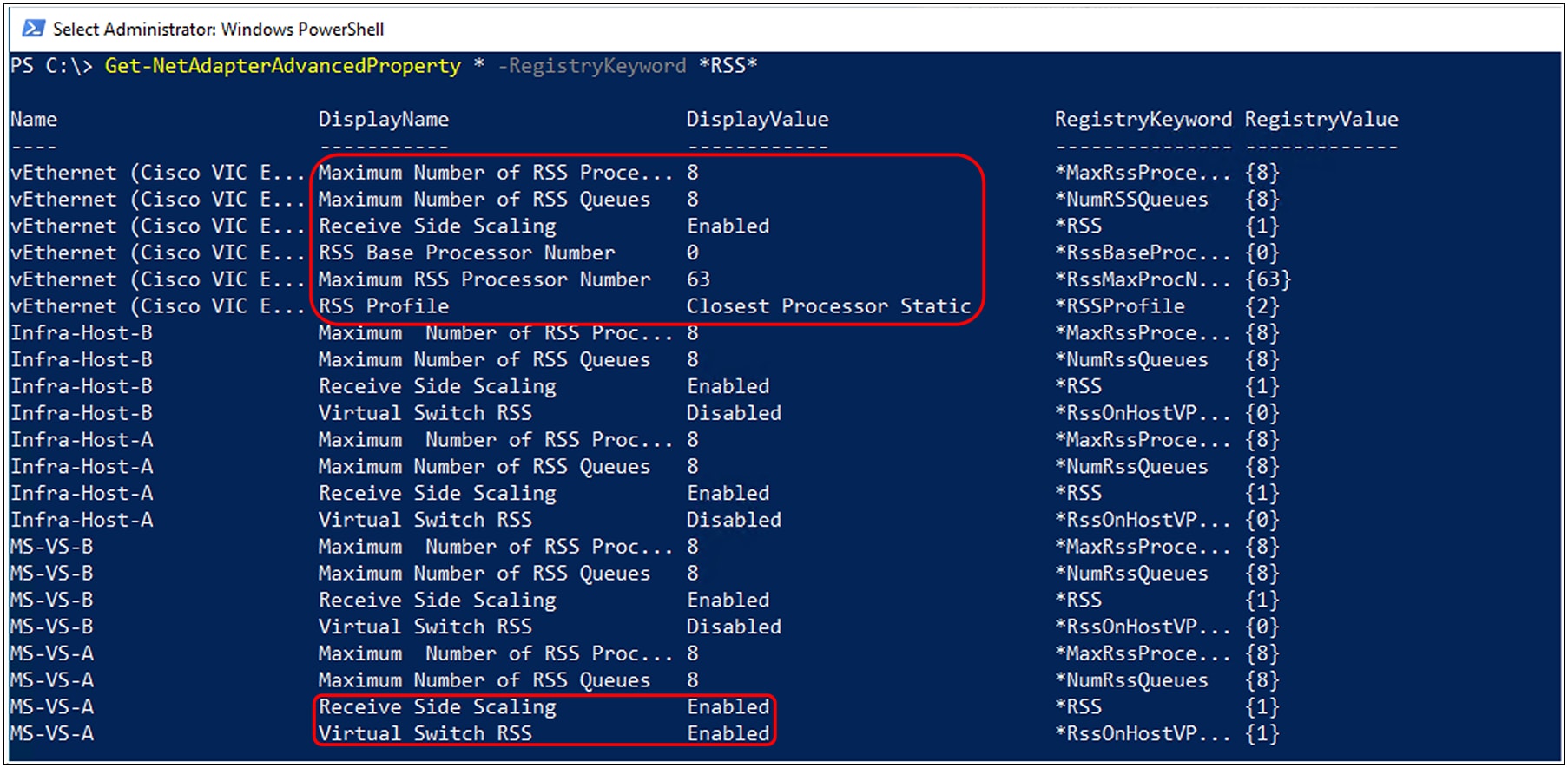
RSSv2 feature enablement on a virtual switch (vSwitch) created on VIC adapter
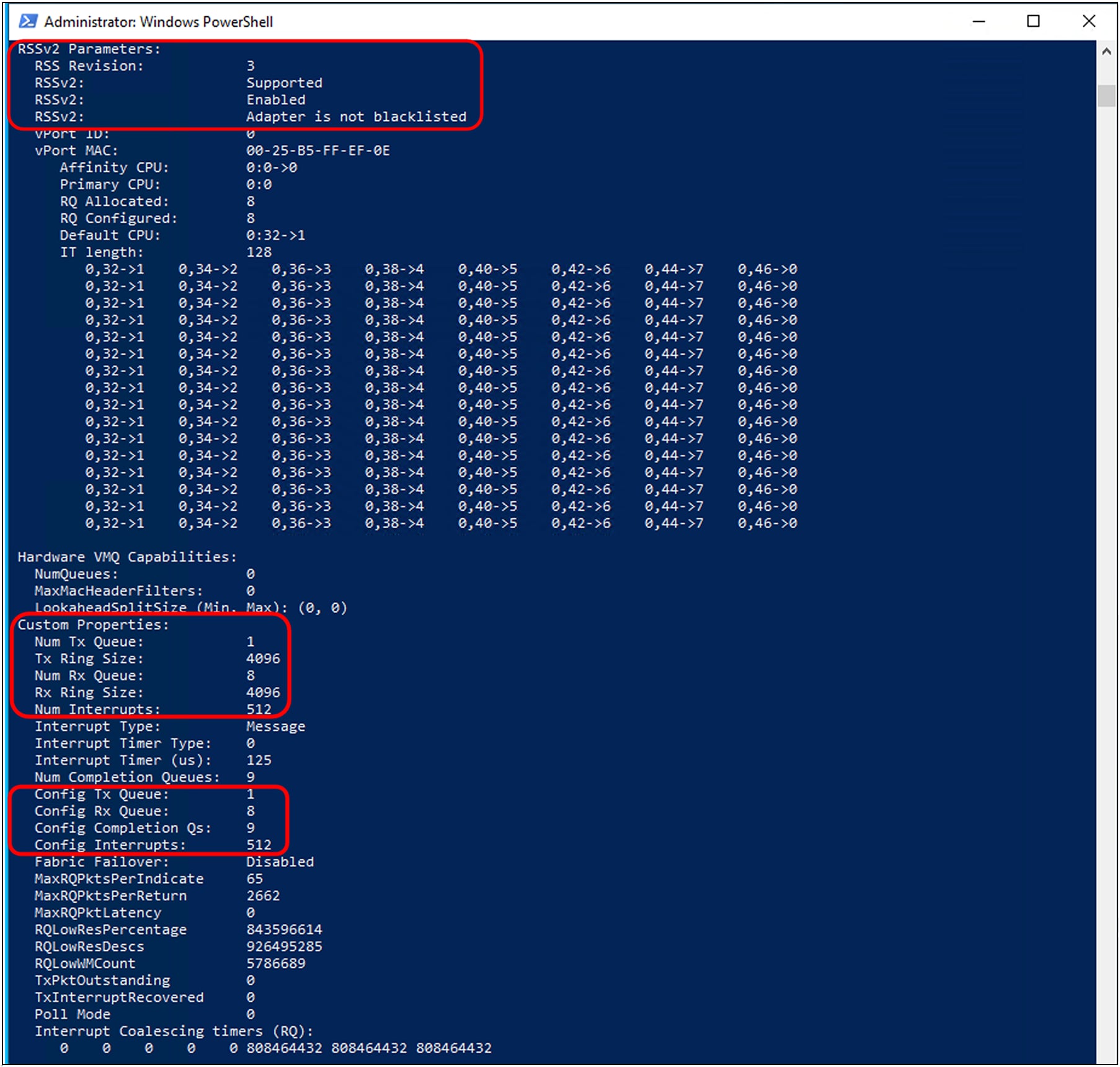
With a Hyper-V host configured with a vSwitch on the Cisco VIC adapter, and running two guest VMs having two vPorts each, Figure 24 shows the RSSv2 configuration in greater detail, with indirect tables, vPorts, VMQ capabilities, and RSS queues.
RSSv2 configuration from a Hyper-V host running two guest VMs with two vPorts each
SR-IOV is an extension to the PCI Express (PCIe) specification that allows devices such as network adapters to separate access to their resources among various PCIe hardware functions. These functions consist of the following two types:
● Physical Function (PF): PF is associated with a hypervisor. PFs are full PCIe functions that can configure and manage SR-IOV functionality. It is possible to configure or control PCIe devices using PFs, and the PF has the full capability to move data in and out of the device.
● Virtual Function (VF): VFs are lightweight PCIe functions that support data flows but have a restricted set of configuration resources.
SR-IOV provides the capability to partition a single physical PCI resource into virtual PCI functions that can then be injected into a VM. In the case of network VFs, SR-IOV improves north-south network performance (that is, traffic with endpoints outside the host machine) by allowing traffic to bypass the host machine’s network stack.
Single-Root I/O Virtualization (SR-IOV) allows multiple VMs running variety of guest operating systems to share a single PCIe network adapter within a host server directly. It allows a single PCIe device (for example, a network adapter) to appear as multiple separate physical devices through VFs. VFs can be PCI passthroughs to guest operating system in virtual machines. This enables VMs to directly interact with PCI hardware without using a VMkernel as an intermediary, thus reducing latency and improving the CPU efficiency of the hypervisor host. SR-IOV allows a VM to move data directly to and from the network adapter, bypassing the hypervisor for increased network throughput.
Beginning with the release 4.3(2b), Cisco UCS Manager provides single-root I/O virtualization high-performance networking (SRIOV-HPN) connection policy support on Cisco UCS M6 and M7 servers with Cisco UCS VIC 15000 Series adapters. SR-IOV support is also available in Cisco Intersight Managed Mode and Cisco IMC. Support is available with a VMWare ESXi hypervisor running Linux guest-operating systems.
Figure 25 shows the relationship between various virtualization objects in a hypervisor host having a SR-IOV- enabled physical network adapter.
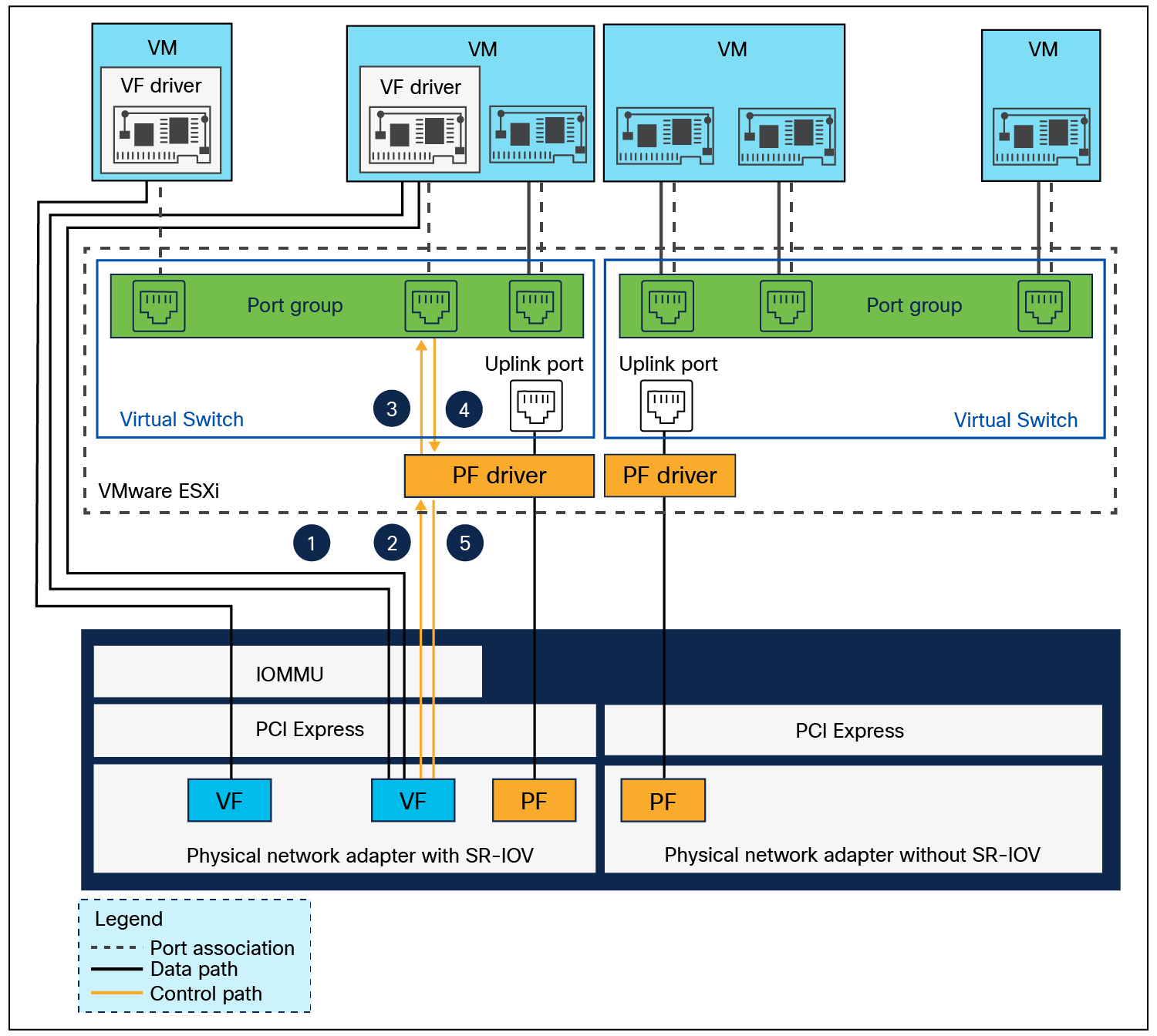
Relationship between PFs, VFs, port groups, virtual switch, hypervisor, and PCIe network adapter
On the SR-IOV-enabled VIC adapter, PF with its SR-IOV VFs, together form a local switching domain. A PF and its VFs not only can transport traffic over the wire to other hosts or to a hardware switch, but can also perform local forwarding between each other. This is made possible by a VIC through a local switch. A packet sent by an SR-IOV VF interface in a VM gets switched locally if the destination MAC address is found to belong to another SR-IOV VF interface used by another VM that has the same PF.
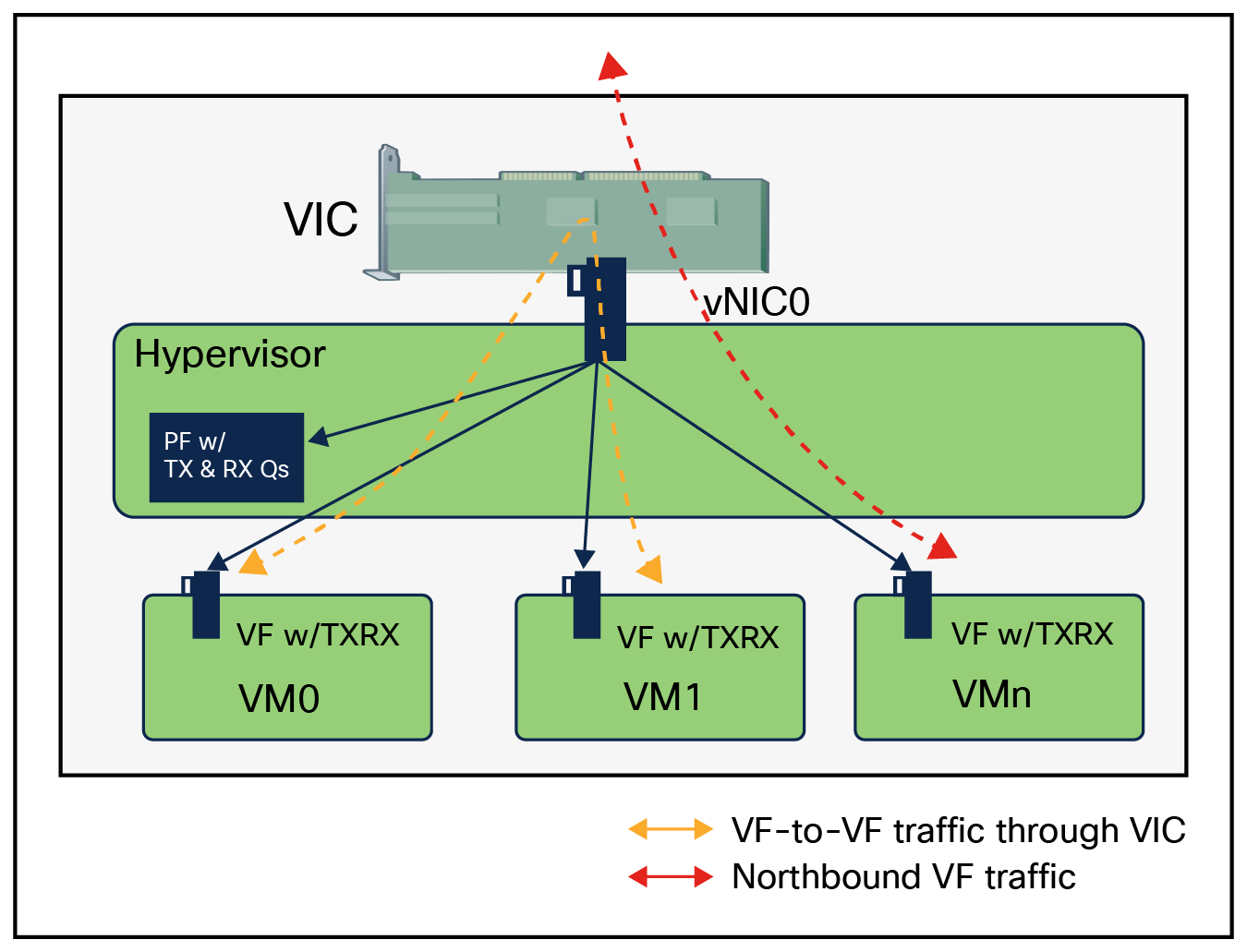
Data path for traffic forwarding on VFs
A SR-IOV-enabled vNIC is compatible the following:
● Consistent Device Name (CDN) support on host interface (PFs) only
● DPDK supported on Linux guest-operating systems (VMs)
● RSS support on the same vNIC
SR-IOV-enabled vNICs using SR-IOV-HPN policy cannot be used with any of the following:
● QinQ
● VXLAN offload
● GENEVE offload
● ENS
● NetQueue
● NetFlow
● RoCEv2
The three steps given below need to be performed to enable the SR-IOV feature in supported operating environments:
● BIOS policy settings for Intel/AMD-processor-based Cisco UCS servers
● SR-IOV vNIC connection policies in UCSM, IMM, and IMC
● Configuration in hypervisor and guest operating systems
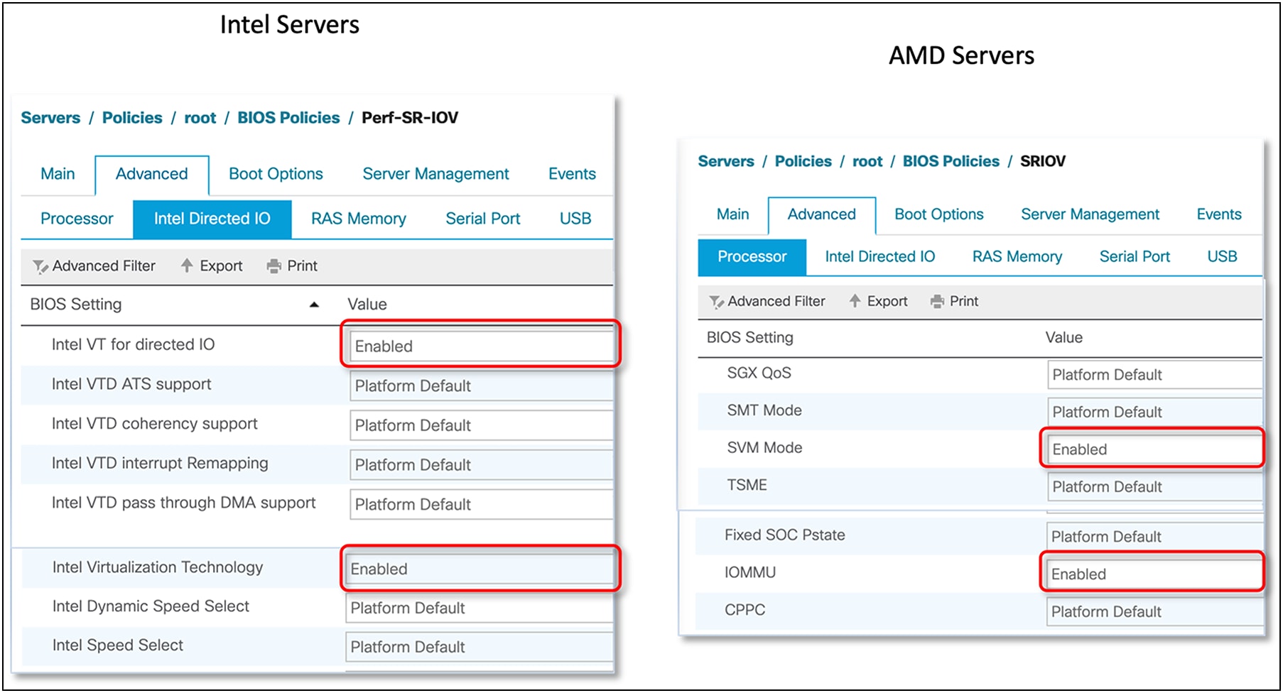
BIOS policies for Intel and AMD processor–based Cisco UCS servers
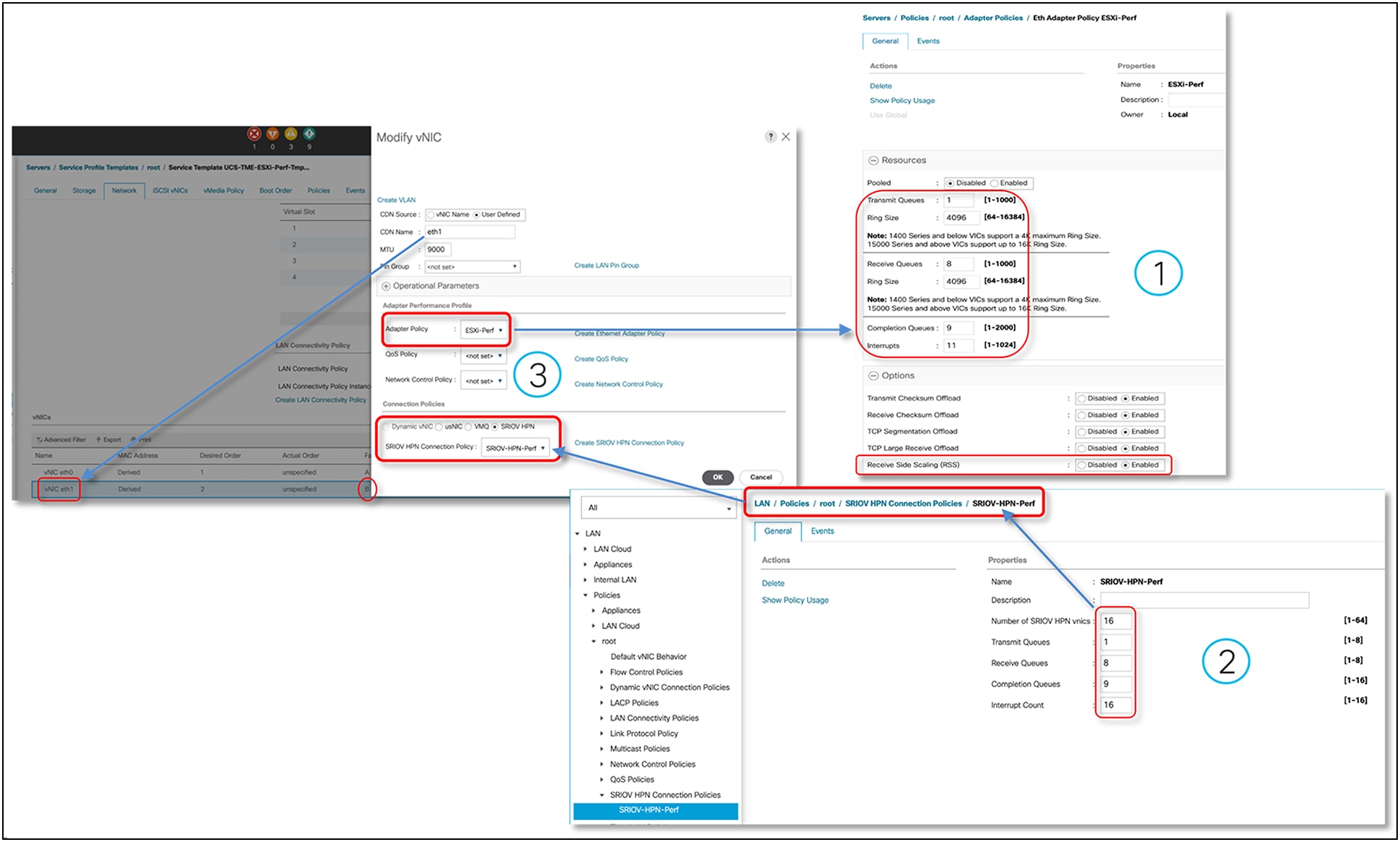
Adapter policy required for SR-IOV in Cisco UCS Manager
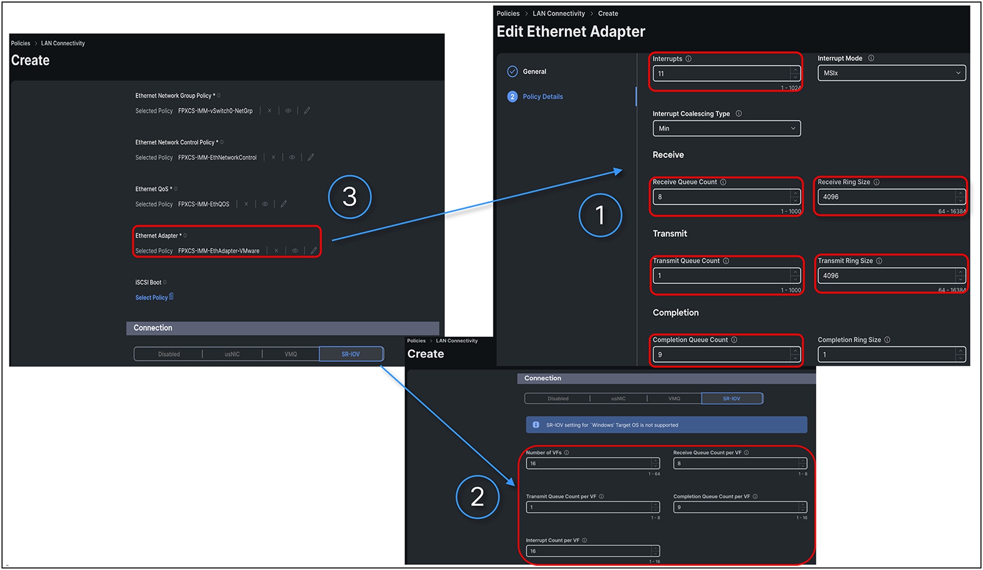
Adapter policy for SR-IOV in IMM
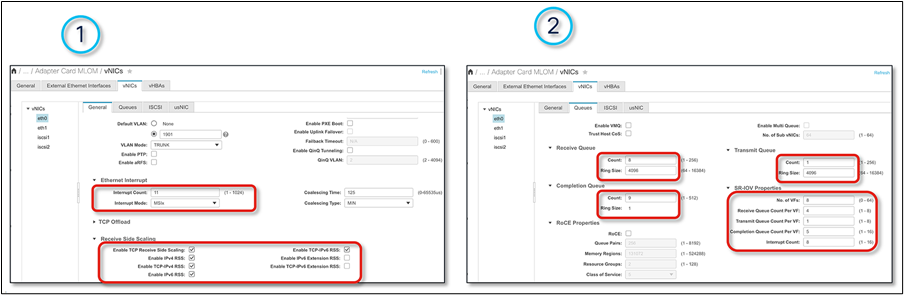
Adapter policy for SR-IOV in IMC
Configurations to enable SR-IOV functionality for the operating environment are required both at hypervisor and guest-operating system levels. VMware vSphere/ESXi 7.0 U3, and later versions, is the supported hypervisor, while Linux OS is for supported guest VMs. At the hypervisor layer, SR-IOV needs to be enabled with the required number of Virtual Functions (VFs). The number of VFs should not exceed the number of VFs set in the SR-IOV policy. On the Linux guest VM, asynchronous eNIC driver version 4.4.0.1-930.X, and later versions, supports SR-IOV VF network interfaces.
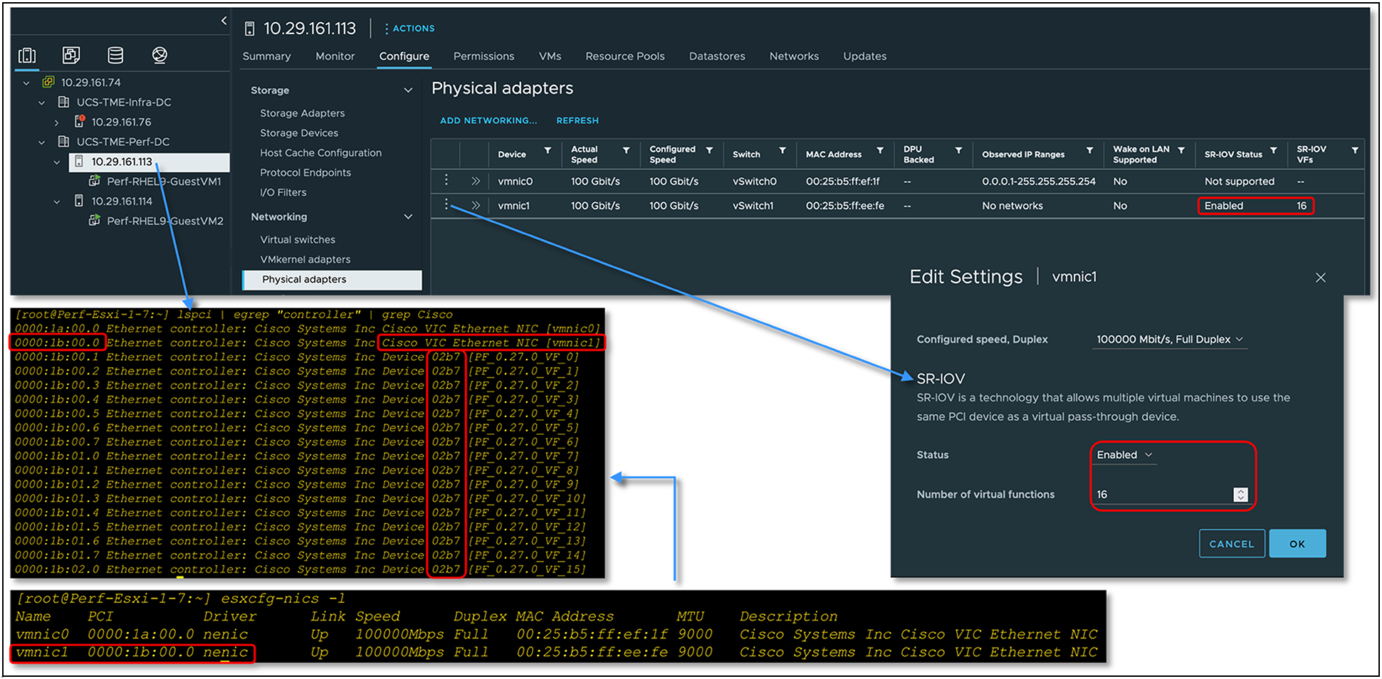
Enabling SR-IOV functionality on ESXi hypervisor with Cisco VIC
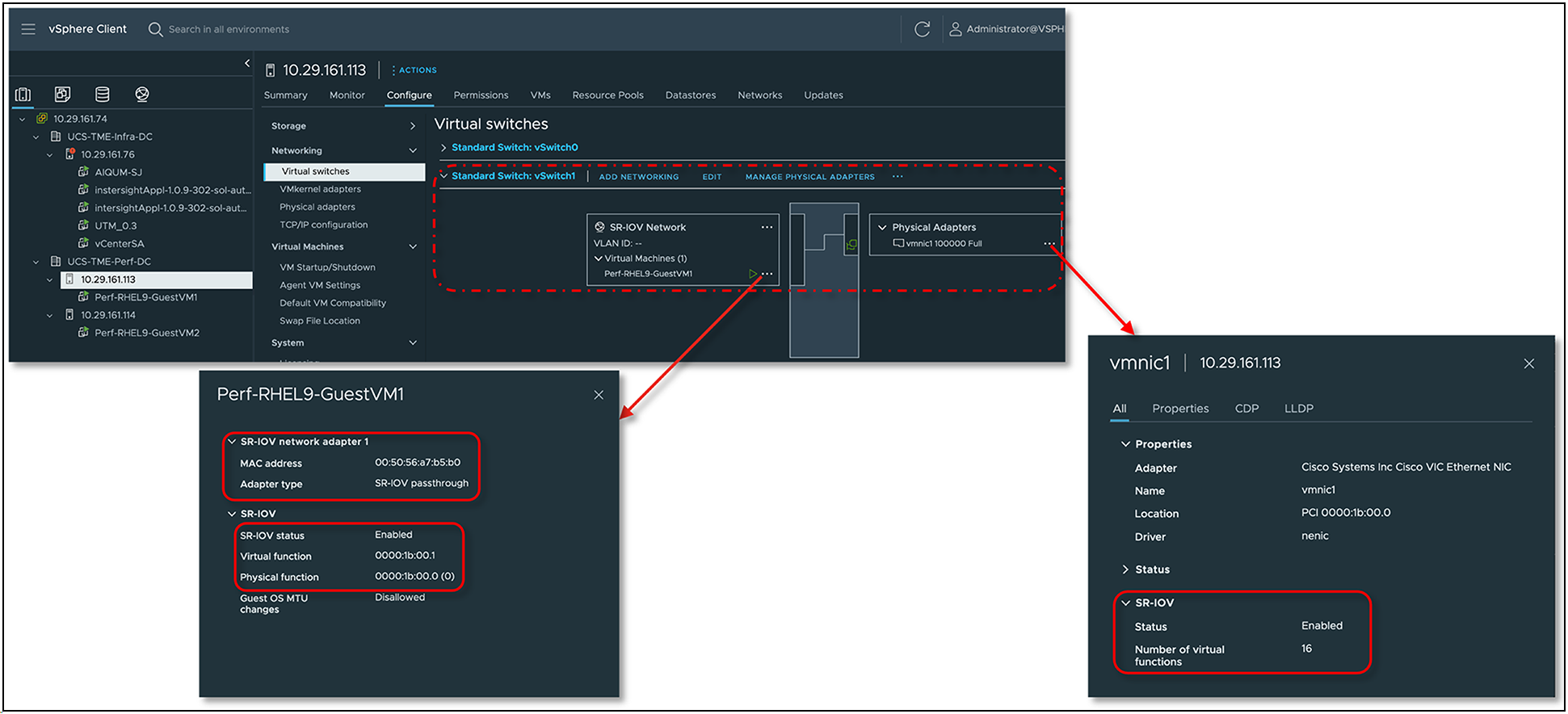
SR-IOV configuration status on ESXi vSwitch
Guest Linux VM boot mode setting should have secure boot mode disabled. The ESXi hypervisor supports Virtual Machines (VMs) using virtual BIOS. The virtual BIOS does not have a Cisco UCS eNIC driver public key installed by default even when running on the UCS server platform. This causes failure to load the asynchronous ENIC driver, resulting in operating system being unable to operationalize the VFs’ network interface devices.
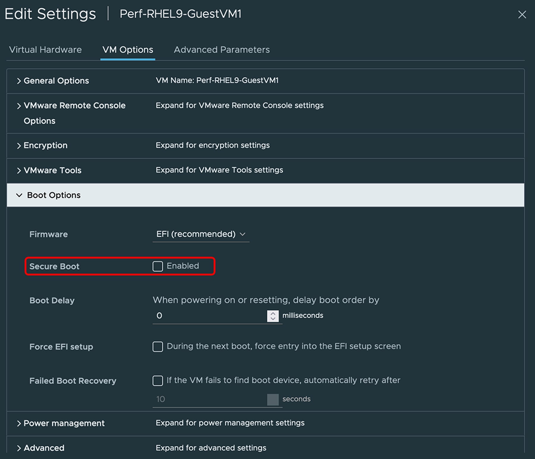
VM option to disable secure boot
Note: For secure booting of guest Linux VMs that have a SR-IOV function, the Cisco UCS driver signing the public key needs to enroll in VM BIOS. The procedure to install the public key will be provided in the Cisco UCS SR-IOV configuration guide.
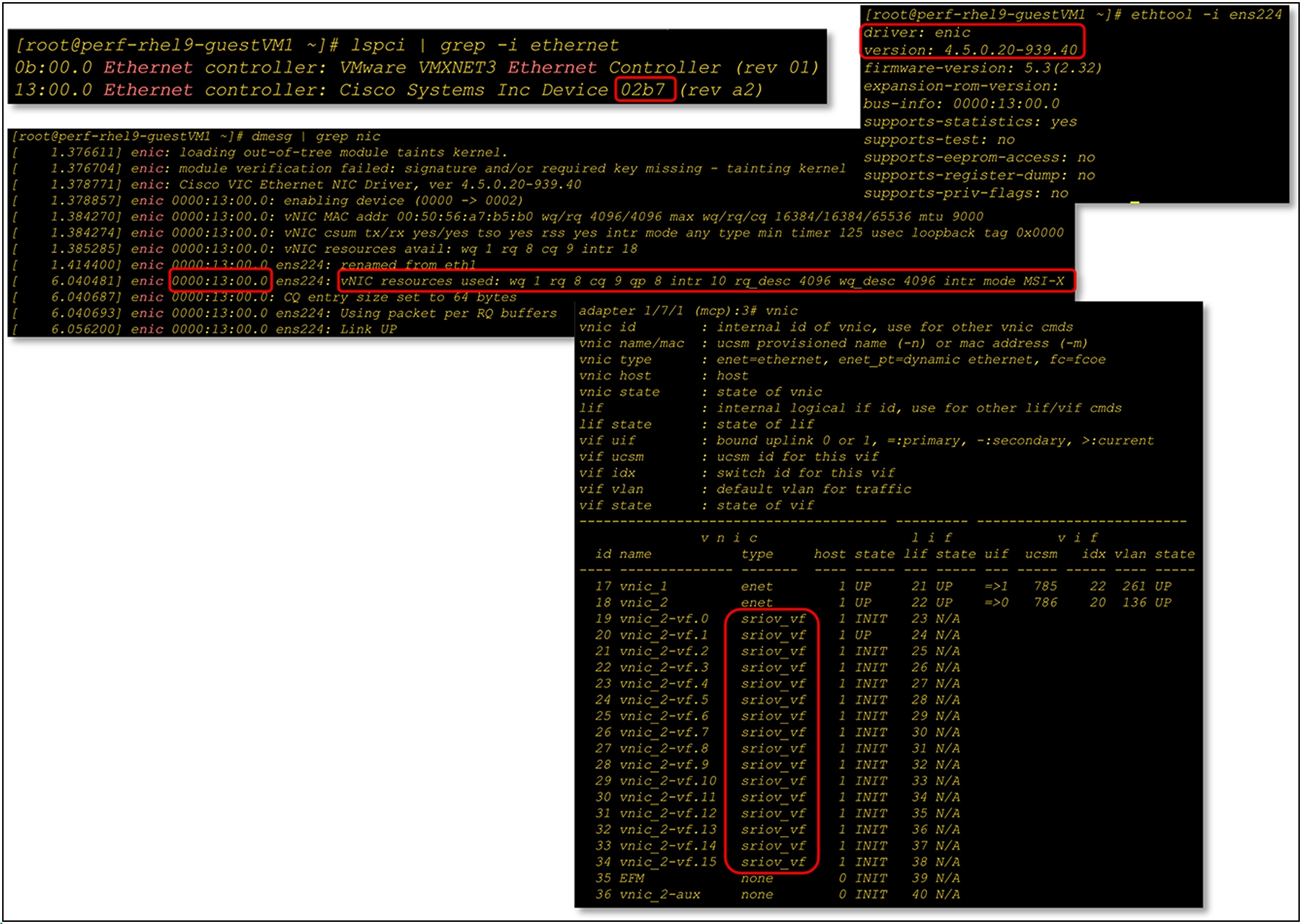
Displaying guest operating system driver version, PCI device status, and VF status at VIC firmware
NetQueue or VMQ on ESXi is a feature like the VIC RSS that can be used to achieve higher performance on Cisco UCS servers. NetQueue is an integrated hardware and software solution from both VMware and Cisco.
NetQueue achieves higher throughput and performance by having dedicated a TX/RX queue per VM. So, while RSS is a hardware feature that enables multiple RX queues across multiple VMs, NetQueue dedicates a TX/RX queue for each VM.
NetQueue takes advantage of the VIC 15000 series capability to deliver network traffic to the system in multiple receive queues that can be processed separately, allowing it to scale to multiple CPUs. Effective use of RX queues as allocated by VIC 15000 to vNICs, is enabled by managing the vNIC and VMkernel NetQueue balancer. This adapter filter is enabled by default in ESXi to use load-balancing algorithms.
Note that on VIC 15000, RSS and NetQueue for ESXi are mutually exclusive features, and so either RSS or NetQueue should be used with ESXi.
NetQueue on the vNIC is enabled through the VMQ connection policy. The following are the considerations for VMQ/NetQueue with ESXi and VIC 15000:
● When using VMQ for ESXi, there is no need to specify an adapter policy in Cisco UCSM/IMM; the default adapter policy is used.
● VIC 15000 can have a maximum of 16 VMQs per vNIC.
● Depending on the number of VMQs defined, the adapter will allocate the same number (TX, RX) queues per vNIC. And each VM gets allocated a dedicated RX queue; on the transmit side, the VM traffic is distributed across multiple TX queues.
● Interrupt for VMQ is calculated as “2 x VMQ + 2”.
● If the VMNIC statistics in the ESXi host show that “rx_no_bufs” is incrementing with VMQ, the potential next step would be to increase the TX/RX queue ring sizes to 4096 using a custom adapter policy.
● Note that the adapter policy used with VMQ would specify only one TX and one RX queue, and that no RSS is supported with an adapter policy when VMQ is used. RSS and VMQ are mutually exclusive for ESXi with VIC 15000.
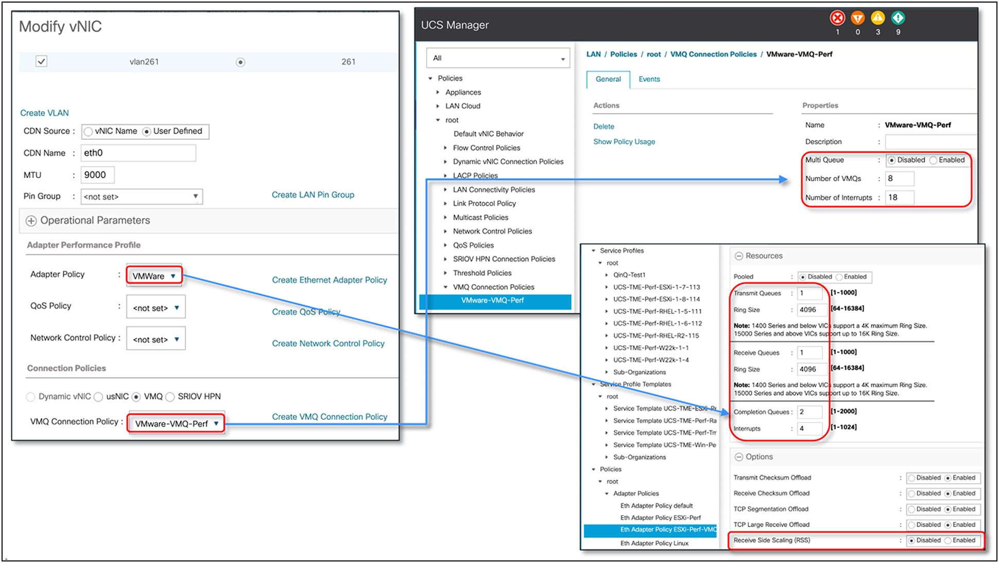
VMQ configuration in UCSM for an ESXi host
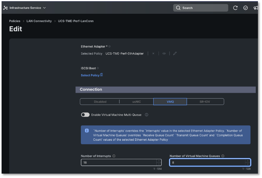
VMQ configuration in IMM for an ESXi host
Queues allocated per vNIC on the ESXi host based on the VMQ configuration
The VIC 15000 can utilize RSS or NetQueue/VMQ with ESXi and, while both provide similar performance, there are a few differentiating factors to decide on which solution suits a server’s needs:
● Traffic hashing for RSS is across Layer-2/3/4 headers whereas VMQ/NetQueue hashes are based on the Layer-2 header of the packet. Thus, when an ESXi host has a greater number of VMs than the maximum number of allowable NetQueue/VMQs, RSS provides better RX traffic hashing or distribution across CPU cores.
● In scenarios involving multiple RX flows to a single VM, RSS can provide higher throughput. The reason is that for NetQueue/VMQ, only a single RX queue is dedicated per VM, whereas, for RSS, the traffic is distributed across all the RX queues of the vNIC.
● VMQ is to be used when an RX queue needs to be dedicated per VM. In the case of RSS, queues are not dedicated per VM.
● VMQ is helpful in scenarios where the TX performance is of concern, since, with VMQ, multiple TX queues are supported, and the traffic from a VM is distributed across multiple TX queues; whereas the adapter policies with RSS support only one TX queue. For server traffic generally, TX is never the bottleneck.
● For overlay networks built on ESXi; the VXLAN, and GENEVE offloads are available only with RSS and not with VMQ on the VIC 15000.
VMMQ, or virtual machine multiple queues, allows you to configure multiple I/O queues to a single VM and thus distribute traffic across multiple CPU cores in a VM. With VIC 15000 we can assign multiple hardware queues from it to a single vPort in a Hyper-V host. VIC 15000 distributes the network traffic across these queues using RSS hashing and places packets directly onto the assigned CPU cores. Offloading traffic distribution to the VIC hardware improves CPU performance, thereby relieving software stack to do other tasks. VMMQ enables efficient distribution of network traffic within VIC hardware.
The Virtual Machine Queue (VMQ) policy with the multiple queue option enabled allows a vNIC to get placed into VMMQ mode. In this mode we can configure sub vNICs and specify a VMMQ adapter policy. This policy includes the aggregate queue counts for VMMQ and determines how the connectivity between VMs and vPorts is configured. So, 64 sub vNICs defined in VMQ policy will equate to 1x64 transmit queues and 8x64 receive queues in aggregate in the corresponding WIN-HPN/-v2 adapter policy. Each sub vNICs gets 1 TX and 8 RX queues.
Figure 38 shows a high-level incoming packet flow from pNIC (Physical Network Interface) to vmNIC within Hyper-V host, with VMMQ enabled. It highlights how incoming packets are placed into the right vPort and corresponding RSS queues for VM CPU cores for processing.[2]
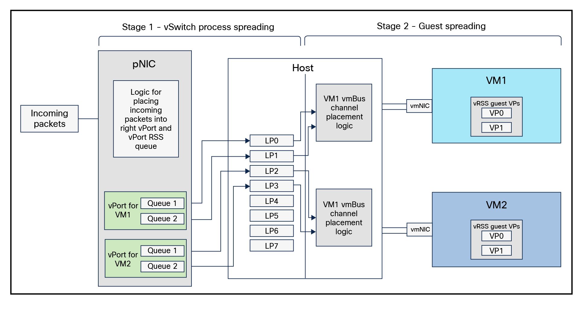
Receive path within the VMMQ interface for incoming network traffic
This diagram highlights the network packet receive path within the VMMQ interface. On the receive path, when a packet arrives at a vNIC with the VMMQ feature configured, the following steps are executed:
1. The destination MAC address is matched to find the target vPort.
2. The RSS hash value of the packet is calculated using the RSS parameters – the secret key, the hash function, and the hash type of the vPort.
3. This hash value is than used to index the Indirection Table (IT) associated with the vPort
4. Then an interrupt call is issued to the target processor (LP = logical processor) with an indication to the host network stack.
5. The final step is to place the packet into the destination VM’s vRSS-enabled Virtual Processor’s (VP’s) packet buffer for processing.
For the VIC 15000, VMMQ is supported in Windows Server 2016 and following; and the recommendation for a Hyper-V host is to use VMMQ. Here are some of the considerations to keep in mind when using VMMQ on VIC 15000:
● On Windows Server 2016, VMMQ is not enabled by default; VMQ is the default option. To enable VMMQ, the server administrator must use the “Set-VMNetworkAdapter” and “Set-NetAdapter” commands.
● Windows Server 2019 supports VMMQ by default and so no explicit configuration is needed on the server.
● VMMQ assigns one TX and multiple RX queues up to a maximum of eight per vPort and is configured through the Cisco UCSM/IMM/IMC Multi-Queue (MQ) policy.
● Use of the predefined Cisco UCSM policies (“Win-HPN-v2” and “MQ-v2) to enable VMMQ and to get optimal performance is recommended; the policy definition is good for 64 vPorts.
● VMQ is a subset of VMMQ and, for VIC 15000, VMMQ is the recommended option.
● VMMQ on Windows supports VXLAN or NVGRE offload support and is enabled with the vNIC adapter policy.
Detailed configuration guidelines for VMMQ are available in the UCSM “Cisco UCS Manager Network Management Guide.”[3]
Summarizing some of these recommendations, enabling VMMQ on a vNIC in Cisco UCSM would require the following two configurations.
● Attach a predefined UCSM adapter-policy “Win-HPN-v2” or a similar custom adapter-policy to the vNIC.
● Include a VMQ connection policy on the vNIC. This policy is user-created under the LAN tab in UCSM and must have multi-queue enabled and use a predefined UCSM “MQ-v2” policy under VMMQ adapter policy drop down.
When multi-queue is enabled, the vNIC is placed into VMMQ mode. In this mode, the user has an option to select the number for sub-vNICs. Each sub-vNIC will have a corresponding adapter policy selected under the VMMQ adapter policy field. Our recommendation is to use the pre-defined system policy “MQ-v2,” which by default enables pool mode. The predefined “MQ-v2” policy includes the aggregate queue counts available across the vPorts for VMMQ and determines how the connectivity between VMs and vPorts/sub-vNICs is configured.
Figure 39 shows the four-step procedure to enable VMMQ on a vNIC using Cisco UCSM’s predefined adapter policies (“Win-HPN-v2” and “MQ-v2”). In the Cisco UCSM/IMM/IMC configuration window, “Sub vNIC” is the same as vPort in Hyper-V parlance. In UCSM, the predefined “MQ-v2” policy is for 64 vPorts and allocates one TX and eight RX queue per vPort.
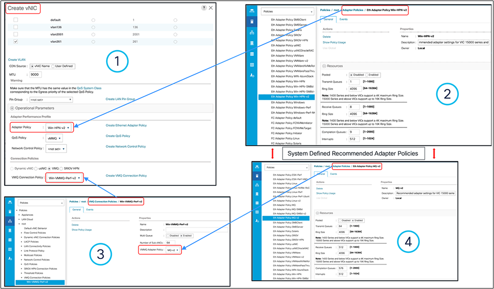
Configuring VMMQ with a predefined adapter and MQ-v2 policy in UCSM
Figure 40 provides the policy configuration details required for enabling the VMMQ feature in Intersight Managed Mode. vNIC creation through LAN connectivity policy will require selecting the pre-defined recommended adapter policies provided by Cisco. The same as in the case of UCSM, we need to select “Win-HPN-v2” and “MQ-v2” policies for vNICs and sub-vNICs. The rest of the configuration details remain same.
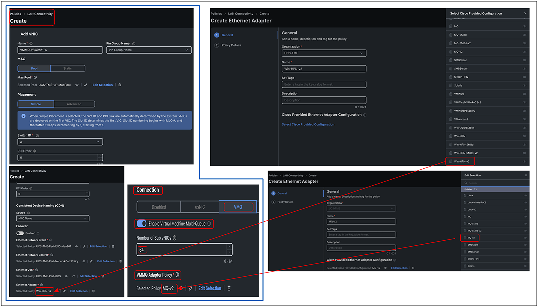
Configuring VMMQ with predefined adapter Win-HPN-v2 and MQ-v2 policies in Cisco Intersight
While the recommendation is to use the above approach to enable VMMQ using pre-defined UCSM adapter policies, you could also define custom VMMQ policies depending on the number of vPorts per host. The calculations for a custom MQ policy would be as follows (in the following custom MQ policy, one TX queue and eight RX queues are allocated per vPort):
● TX queue = Sub vNIC or vPort
● RX queue = 8 x (TX queue)
● CQ = TX + RX
● Interrupt = 512 OR at least “2xCPU+ 4”
● Pooled under Resources “Enabled”, and RSS under Options “Enabled”
Note: The VIC 15000 Series adapter has, per adapter, a maximum hardware limit of 3072 interrupt counts. As such, a maximum of five vNICs with 512 interrupt counts each is supported. The remaining interrupt counts are reserved for system use.
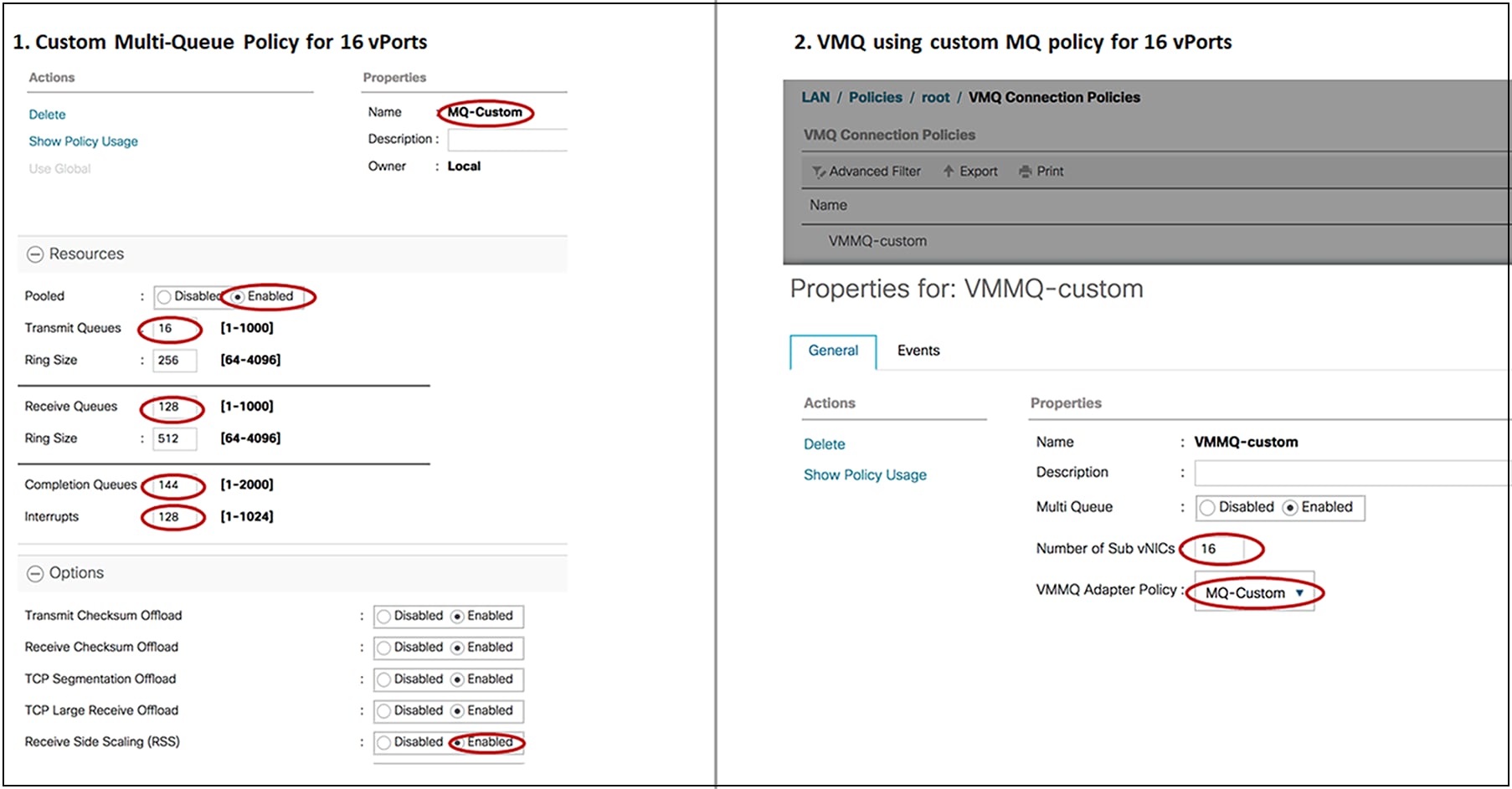
Defining custom MQ policy in UCSM for 16 vPorts
Figure 42 is a screen capture from a Hyper-V host with a single Hyper-V vSwitch and SET teaming across two vNICs. There are two VMs on the Hyper-V host with two vPorts per VM. And each vPort on the VM will have allocated one TX and eight RX queues, based on the MQ-v2 policy.
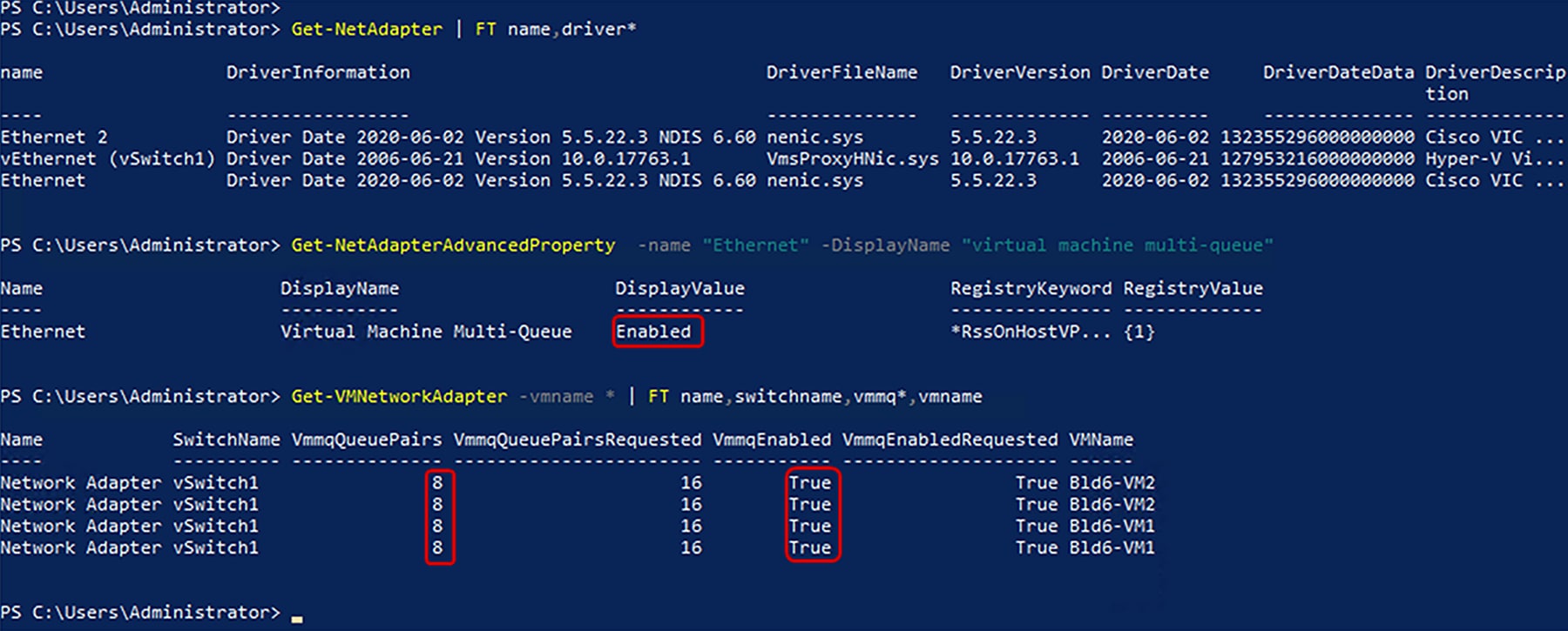
VMMQ information from a Windows Server 2019 Hyper-V host
Below are some of the important guidelines applicable to VMMQ with VIC 15000 Series adapters:
● Each VMMQ vPort may use one transmit queue and multiple receive queues. When VMMQ is enabled, a pool of queues is created, and the host driver assigns queues to vPorts. Different vPorts may be assigned different numbers of queues based on the number of cores that the vPort will be servicing.
● VXLAN and NVGRE offloads are supported with VMMQ functionality. The option is enabled in the vNIC adapter policy and not in the sub vNIC adapter policy.
● RSS is supported on VMMQ receive queues, including inner packet of overlay networks.
● VMMQ vNICs support a rate limit set by the host, not from Cisco UCS Manager. CoS will not be adjustable per vPort from Cisco UCS Manager.
● vNICs with the VMQ feature, specified through the VMQ connection policy with multi-queue disabled, are not allowed on the same adapter as multi-queue-enabled vNICs.
● FCoE and VMMQ vNICs can coexist on the same server.
● usNIC and VMMQ cannot be enabled on the same VIC.
● Modifying the VMMQ adapter policy through the VMQ connection policy results in exceeding the maximum Completion-Queue (CQ) value. VIC 15000 Series adapters support up to a maximum of 2000 hardware CQ resources. If this number is exceeded, it results in an “out of CQ resources” error while deploying a service profile at the vNIC creation stage. This results in eventual failure to create a vNIC.
● The following PowerShell (PS) command can be used to enable VMMQ on the vPort:
◦ Set-VMNetworkAdapter -VMName (VM_NAME) -VmmqEnabled $true -VmmqQueuePairs (Queue_Pair_Count) -VrssEnabled $true
Along with RSS, VMQ, and VMMQ support, another feature that VIC 15000 supports is RDMA over converged Ethernet version 2 (RoCE v2), which is available for all supported operating systems. The detailed configuration and recommendations for RoCEv2 are available in the “Cisco UCS Configuration Guide for RDMA over Converged Ethernet (RoCE) Version 2.”[4]
The other consideration to drive better performance is to have jumbo frame enabled throughout the fabric and on the servers.
For Cisco UCS servers connected to fabric interconnect in UCSM or IMM mode, the user needs to enable the following for the supporting of jumbo frames:
● Configure jumbo MTU on the fabric-interconnect QoS class
● Set MTU on the vNIC through the adapter-policy
● For Linux, the vNIC MTU is reflected on the OS; for Windows, the MTU needs to be set on the server as well.
When the VIC is not connected to a fabric interconnect, the fabric level MTU on a Cisco Nexus® or third-party switch should be enabled to carry jumbo frames. Additionally, MTU is one of the vNIC properties that can be configured in Cisco UCSM/IMC; the recommended value for vNIC MTU is 9000.
For ESXi environments, the vSwitch/DVS and the virtualized network adapter MTU (for example, VMXNET3 for ESXi) should be configured to handle jumbo frames, with considerations for GENEVE or VXLAN headers if overlays are set up from the server.
Note that, on Linux and ESXi hosts, the MTU set on the Cisco UCSM/IMM/IMC vNIC gets reflected on the host, but for Windows servers, the MTU set on the vNIC does not take effect - for Windows, the user needs to explicitly set the adapter MTU to jumbo frames from the Windows server.
The VIC 15000 Series adapters support overlay offloads, including VXLAN, GENEVE, or NVGRE. An overlay offload on a VIC enables TCP Segmentation Offload (TSO), TX/RX checksum offload for inner/outer packets, and RSS on the inner payload of the tunneled packet. The overlay offload on VIC cards thus provides the following advantages:
● Reduced CPU utilization: A TSO and TX checksum offload overlay helps reduce CPU utilization significantly on the transmit side. And the receive side benefits from RX checksum offload.
● Better throughput: Higher throughput can be achieved by enabling an overlay offload with multiple RX queues and RSS. With multiple RX-queues, RSS, and overlay offload enabled, the VIC ASIC spreads traffic across multiple CPU cores based on the inner payload hash of each tunneled packet. Without hashing on the inner payload, traffic would be hashed based only on the outer overlay header (VXLAN/GENEVE/NVGRE). Having hash based on the inner payload provides efficient distribution across multiple CPU cores, thus, having VXLAN/NVGRE/GENEVE overlays from the server helps to achieve higher throughputs.
VXLAN offload
The VIC 15000 Series supports VXLAN offload with IPv4 and IPv6 payloads for ESXi, Linux, and Windows. With multiple RX queues and RSS along with VXLAN offload enabled, packets can be load balanced across multiple CPU cores based on the inner payload.
The recommended adapter policy with VIC 15000 for VXLAN overlays is to have the following:
● Multiple RX queues with RSS enabled
● TX/RX queue-size of 4096
● VXLAN offload enabled
VXLAN-offload-recommended adapter-policy for VMware
For VMware, VXLAN offload is supported only with RSS and not with VMQ or NetQueue.
The above defined adapter-policy for VMware is applicable for Linux too; please note that VXLAN offload is different from OVS offload, and OVS offload is not supported on Cisco UCS VIC adapters.
For Hyper-V environments, VMMQ is the recommended solution to be used with VXLAN offload. Additionally, on Windows, NVGRE offload is also supported on the VIC 15000. VXLAN offload is the most deployed and recommended offload solution on the Windows platform.
VXLAN-offload-recommended high-performance adapter-policy for Windows
GENEVE offload
GENEVE offload on the fifth-generation VIC is supported for VMware ESXi starting from Cisco UCSM and Cisco Intersight Managed Mode Release 4.2(3).
GENEVE offload on the VIC 15000 supports the NSX-T vSwitch (N-VDS or VDS 7) in “standard mode” from Cisco UCSM and Cisco Intersight Managed Mode (IMM) Release 4.2(3) and the NSX-T vSwitch in “enhanced data path mode” from Cisco UCSM and Cisco Intersight Managed Mode Release 4.2(3).
Please refer to the Cisco UCS release notes for the supported ESXi versions across releases.
GENEVE offload for N-VDS in standard mode
GENEVE offload for N-VDS in standard mode is supported on VIC 15000 with RSS to provide better CPU utilization and higher throughput. In this mode, VIC 15000 provides RSS on inner packets, TSO for IPv4/v6 packets, and TX/RX checksum offload for IPv4/v6 inner/outer packets.
The recommended settings are as follows:
● Multiple RX queues with RSS
● TX/RX ring size of 4096
● Enable GENEVE offload
Figure 45 shows the adapter policy required for enabling N-VDS in standard mode. Additionally, on NSX-T the user would create an NSX-T vSwitch in standard mode.
GENEVE-offload–enabled adapter-policy for standard N-VDS vSwitch
GENEVE offload for N-VDS in enhanced data path mode (ENS)
Enhanced data path mode (alternatively called ENS) on ESXi uses DPDK-like techniques to provide higher throughput. Notably, ENS utilizes polling to achieve high packet rates. When ENS is enabled, vSwitch uses the VMware ENS stack and utilizes the VIC ENS driver (nenic-ens) for its uplink ports.
The VIC ENS driver for the VMware ESXi operating system is identified as `nenic-ens`, separate from `nenic` driver used for operating in standard mode. Depending on the mode of operation set to standard or ENS on NSX-T vSwitch, the ESXi operating system selects appropriate driver `nenic` or `nenic-ens`.
The VIC ENS driver `nenic-ens` supports TSO for both IPv4 and IPv6, GENEVE offload with IPv4/v6 outer header, TX/RX checksum offload for IPv4/v6 inner/outer packets, and NetQueue. NetQueue is also known as GENEVE filter in ESXi environments. It is to be noted that the VIC ENS driver `nenic-ens` supports NetQueue but not RSS. NetQueue support is available starting with Cisco UCSM/IMM release 4.3(4a). Prior to release 4.3(4a), VIC `nenic-ens` driver uses a single TX/RX queue.
The recommended adapter policy settings for GENEVE offload with ESXi ENS with releases prior to 4.3(4a) are as follows:
● Single TX/RX queue
● TX/RX ring size of 4096
● Enable GENEVE offload
For release 4.3(4a), the recommended adapter policy is to enable NetQueue for the ENS mode to utilize multiple TX/RX queues:
● Multiple TX/RX queues
● Enable Advance Filter
● Enable GENEVE offload
● Enable VMQ connection policy with two or more VMQ queues, applied to vNICs for VM data path
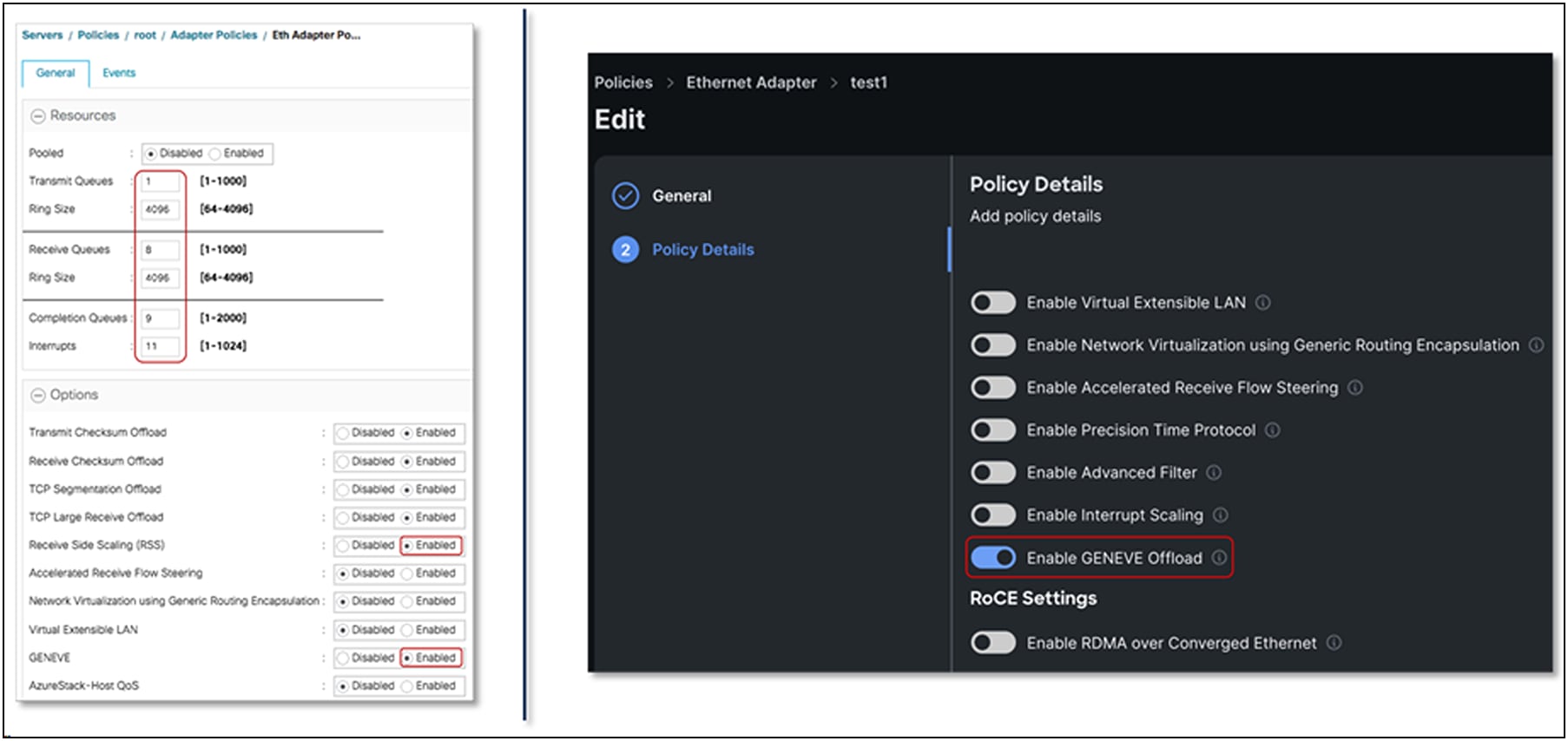
Figure 46 shows the adapter policy required for enabling NSX-T vSwitch in enhanced data path mode. Additionally, on the NSX-T vSwitch, the user needs to select creation of NSX-T vSwitch in enhanced data path mode.
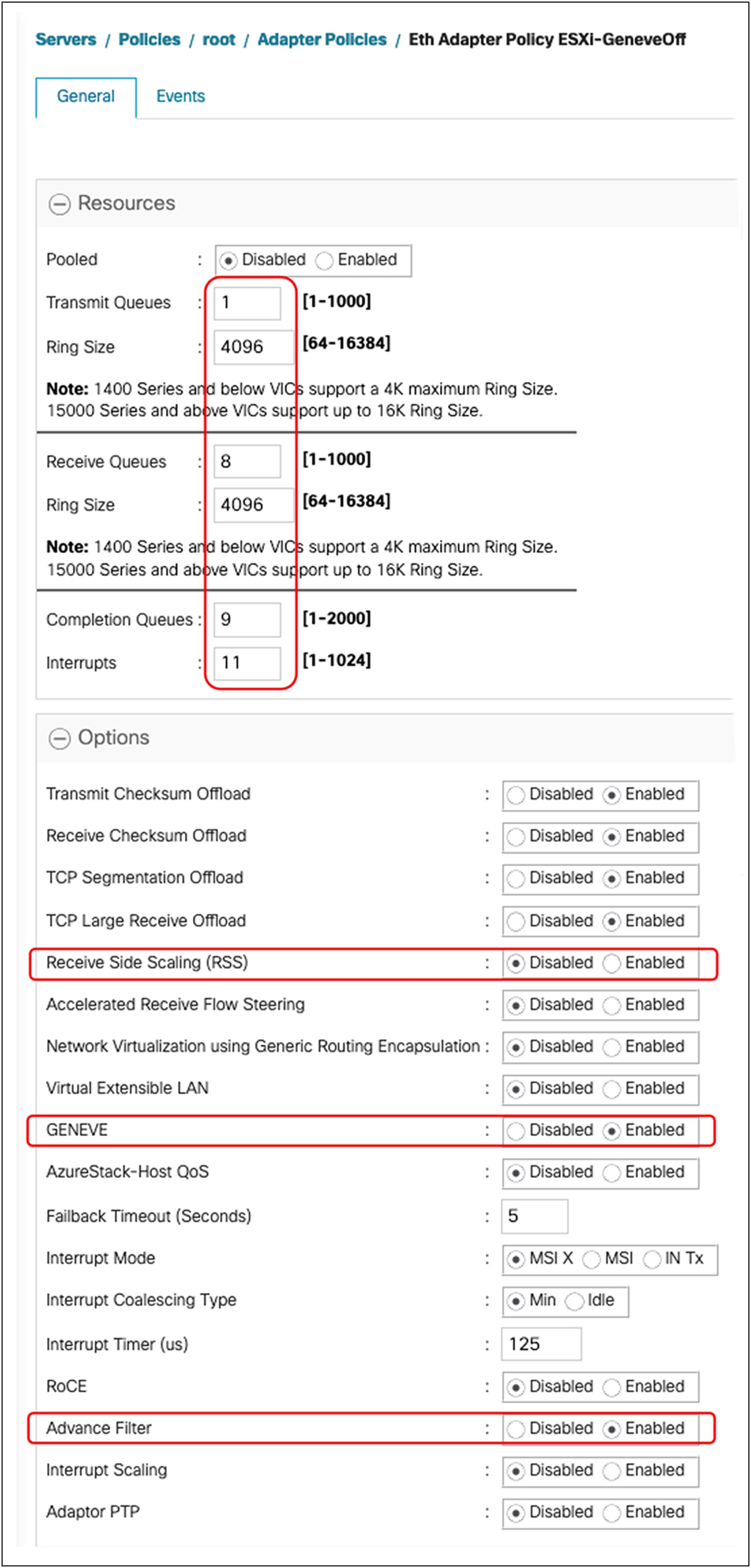
GENEVE-offload–enabled adapter-policy for enhanced data path mode
VLAN Q-in-Q tunneling (also known as VLAN double tagging) is a networking feature that extends the capabilities of Virtual LAN (VLAN) technology by allowing the encapsulation of multiple VLANs within a single Ethernet frame. This feature is defined in RFC 802.1Q-in-Q, which specifies the standards and procedures for implementing VLAN stacking. A Q-in-Q (802.1Q-in-802.1Q) tunnel allows segregating the traffic in the infrastructure and helps to expand the VLAN space through the addition of 802.1Q tags to already 802.1Q-tagged packets.
In a traditional VLAN environment, a single VLAN tag is added to an Ethernet frame to identify the VLAN membership of the frame. However, in scenarios where there is a need to transport VLAN-tagged traffic over a network that already employs VLAN tagging, VLAN Q-in-Q provides an effective solution.
With Cisco UCS VIC QinQ tunneling, two sets of VLAN tags are used. The original VLAN tag, called the outer tag, identifies the customer's VLAN, while the second VLAN tag, known as the inner tag, represents the customer's sub-VLAN. This double tagging process allows for the stacking of VLANs, creating a hierarchical structure of VLANs within VLANs. The outer tag consists of the standard 802.1Q VLAN tag, which contains the VLAN ID (VID) and other control information. The inner tag, also an 802.1Q VLAN tag, carries the VLAN ID specific to the customer's sub-VLAN. By adding these two sets of tags, the VLAN Q-in-Q feature enables the transport of VLAN-tagged frames across multiple VLAN-aware devices and networks.
Here is an example of a packet walk-through between VMs hosted on Cisco UCS servers behind a pair of fabric interconnects, using the Cisco UCS VIC Q-in-Q tunneling feature. It highlights Layer-2 segmentation using double tagging with the Q-in-Q tunneling feature for VLAN IDs 5 and 6 as inner VLANs while VLAN ID 11 is being used as the outer VLAN.
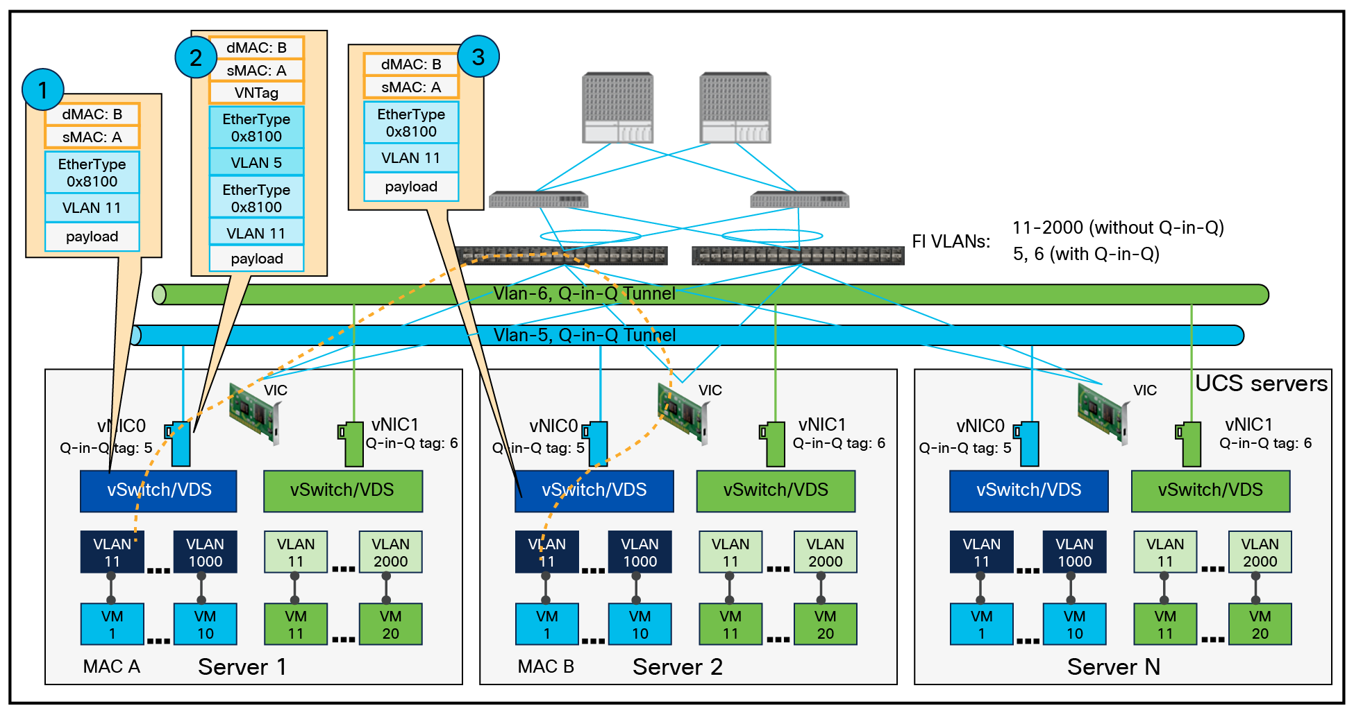
L2 segmentation for tenant VMs hosted in a Cisco UCS environment with the Q-in-Q tunneling feature
This feature is particularly useful in multitenant environments, such as data centers or service provider networks, where different customers or user groups require separate VLAN domains. End-users benefit from VLAN Q-in-Q by having the ability to create and manage their own VLANs within a larger service provider network. This allows them to establish isolated virtual networks, ensuring security and performance while leveraging the advantages of VLAN technology. Additionally, the hierarchical structure provided by double tagging enables the extension of VLANs across different network domains without conflict.
VLAN Q-in-Q, as defined by RFC 802.1Q-in-Q, enhances the capabilities of VLAN technology by allowing the stacking of multiple VLANs within a single Ethernet frame. This feature provides flexibility, scalability, and improved isolation for network deployments, benefiting both service providers and end-users in achieving efficient and secure network operations.
Below are sample use cases for the VLAN Q-in-Q feature:
1. Service provider networks: Service providers often use VLAN Q-in-Q tunneling to segregate or isolate traffic from different customers or to transport customer VLAN traffic across their backbone. This allows service providers to maintain customer traffic separately even if the customers are using the same VLAN IDs.
2. Large enterprise networks: Large organizations with complex networks can use VLAN Q-in-Q tunneling to simplify the management of VLAN IDs across their networks. It allows them to use the same VLAN ID in different parts of the network without causing overlap or conflicts.
3. Network expansion: VLAN Q-in-Q tunneling can help in situations where the VLAN space is exhausted. Since it allows for stacking of VLAN tags, it can effectively expand the VLAN space.
4. Security: By segregating traffic based on customer or department, VLAN Q-in-Q tunneling can add an extra layer of security. It can help prevent unauthorized access to sensitive data by keeping different types of traffic isolated from each other.
5. Multitenant environments: In multitenant environments, such as data centers, Q-in-Q tunneling can be used to keep the traffic of different tenants separate and secure.
The VIC Q-in-Q tunneling feature is supported starting with Cisco UCSM Release 4.3(2).
Configurations required in Cisco UCS Manager:
● Enable Q-in-Q globally under the FI domain through LAN global policy in UCSM
● Enable Q-in-Q under VLAN in vNIC or enable Q-in-Q on vNIC in an LAN connectivity policy
● For untagged traffic, select “Native” under a vNIC
● Upstream network switches should allow Q-in-Q forwarding. Cisco Nexus 9000 Series Switches require “system dot1q tunnel transit” configuration.
● For standalone fabrics, ensure that the upstream ToR switch will carry double-tagged 802.1Q frames.
The rule for using VIC Q-in-Q tunneling can be applied in the following possible scenarios:
● Case 1: Q-in-Q disabled. Native VLAN and multiple VLANs are allowed under a vNIC (legacy behavior).
● Case 2: Q-in-Q enabled. Native VLAN and Q-in-Q VLAN can be the same. Additional VLANs are not allowed under a vNIC. For example, VLAN 201 as both native and Q-in-Q tag: in this case, untagged traffic will be carried with a single-tag of VLAN ID 201, and tagged traffic will be double-tagged, with the outer-tag being 201.
● Case 3: Q-in-Q enabled, and native VLAN and Q-in-Q VLAN being different. In this case also, additional VLANs are not allowed under vNIC. For example, VLAN 201 as native and VLAN 301 as the Q-in-Q tag: in this case, untagged traffic will be carried with a single tag of 201, and tagged traffic will be double-tagged, with an outer-tag of VLAN ID 301.
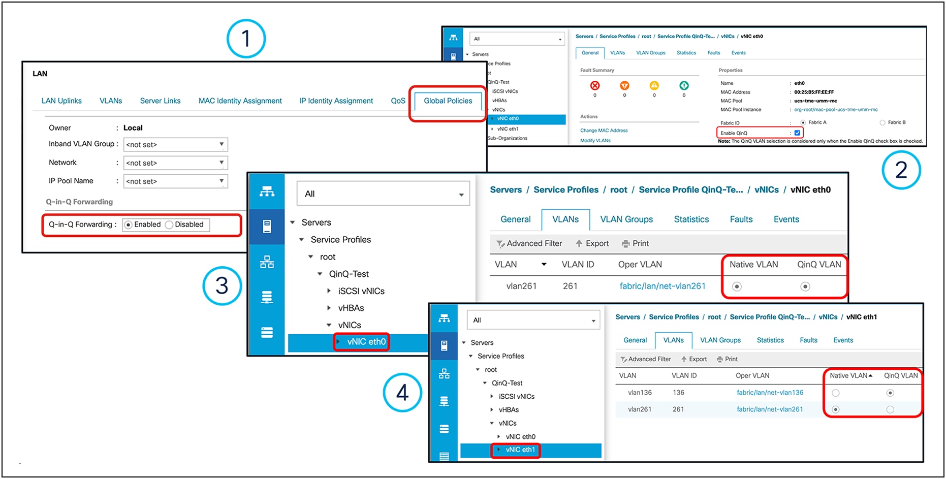
Example of a Cisco UCSM VIC Q-in-Q tunneling configuration
The Q-in-Q tunneling feature is available in Cisco Intersight for UCS C-Series servers in Intersight standalone mode (ISM). For the Cisco UCS B-Series/X-Series/C-series servers in Intersight Managed Mode (IMM), this feature will be available in future releases. For configuring Q-in-Q tunneling, Ethernet network policy should be created with Q-in-Q VLAN IDs.

Example of Q-in-Q tunneling configuration for standalone UCS C-Series servers managed through Intersight
The following considerations need to be kept in mind when configuring the Q-in-Q tunneling feature with Cisco VIC 15000 Series adapters:
● Q-in-Q VLAN selection is effective only when the “Enable QinQ” check box is selected on a vNIC interface, as shown in item no. 2, Figure 49 above.
● For Cisco UCS 6454, 64108, and 6536 fabric interconnects, Q-in-Q must be enabled at LAN > Global Policies to support Q-in-Q VLAN on a VIC adapter, as shown in item no. 1, Figure 48 above.
● Cisco VIC 15000 Series adapters support enabling GENEVE offload and Q-in-Q on a vNIC interface.
● Q-in-Q configuration supports a maximum of two VLANs on a vNIC interface. A Q-in-Q VLAN can be a native or a non-native VLAN. You can configure a native VLAN and a non-native VLAN as a Q-in-Q VLAN on the vNIC.
● The default VLAN (VLAN ID: 1) is not supported as a Q-in-Q VLAN on a vNIC interface.
● When a native VLAN and a Q-in-Q VLAN are configured on a vNIC Interface, a new VLAN configuration is not supported and results in server-profile-association failures when selected. To accommodate a new VLAN, either the native VLAN or the Q-in-Q VLAN must be removed.
● When the Q-in-Q VLAN is the same as the native VLAN on a vNIC Interface, a new VLAN configuration is not supported and results in server-profile-association failures when selected. To accommodate a new VLAN, either the native VLAN or Q-in-Q VLAN must be modified.
● When VIC Q-in-Q tunneling is enabled, downgrades to release version lower than 4.3(2) is not possible.
● On an associated service profile on UCS B-Series servers, you cannot enable or disable Q-in-Q VLAN settings.
Q-in-Q VLAN-enabled vNICs created on VIC 15000 Series adapters cannot be used in the following:
● LAN (or PXE) boot
● iSCSI boot
● SR-IOV
● VMMQ
● RDMAv2
● usNIC
The Precision Time Protocol (PTP) is used to synchronize clocks running on devices in a network. Cisco VIC 15000 Series adapters provide PTP support in hardware, and work in conjunction with the protocol software stack to provide sub-microsecond accuracy in clock synchronization. This is far better than what is normally obtainable with Network Time Protocol (NTP). One of the main advantages of using PTP with Cisco VIC 15000 Series adapters over NTP is that the hardware support available on the VIC 15000 series allows PTP to account for delays in message transfer, and greatly improves the accuracy of time synchronization. With hardware-enabled PTP, VIC 15000 Series adapters have their own onboard clock, which is used to time stamp received and transmitted PTP messages. Hardware support for PTP enables VIC to time stamp the PTP packets at the exact moment they are sent and received.
To achieve the best possible accuracy, it is recommended that all networking components between PTP clocks be PTP hardware enabled. Time synchronization in larger networks where not all the networking hardware supports PTP, might be better suited for NTP.
PTP is available on Linux operating systems only and can be enabled on one vNIC per VIC 15000 Series adapter at a time. PTP precisely synchronizes the server clock with other devices and peripherals on Linux operating systems.
Clocks managed by PTP follow a primary-worker hierarchy, with workers synchronized to a master clock. The hierarchy is updated by the Best Master Clock (BMC) algorithm, which runs on every clock. One PTP interface per adapter must be enabled to synchronize it to the grand master clock. After enabling PTP, the host must be rebooted.
The time stamping parameters displayed by `ethtool -T int_name` will show a field for the PTP hardware clock. The value of PTP Hardware Clock: 0 shows that PTP is enabled for the interface. Otherwise, it will show PTP Hardware Clock: none.
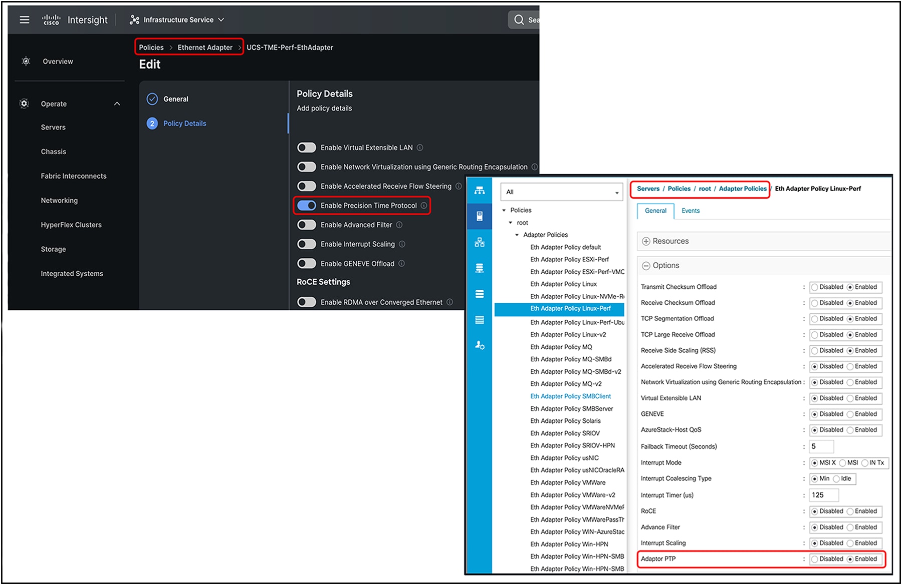
PTP enablement through adapter policy in IMM and UCSM, respectively
FEC settings on 15425/15427/15428/15235/15237/15238
Forward Error Correction (FEC) is a method of obtaining error control in data transmission over an unreliable or noisy channel in which the source (transmitter) encodes the data in a redundant way using error-correcting code, and the destination (receiver) recognizes it and corrects the errors without requiring retransmission.
A Forward Error Correction (FEC) setting for a VIC 15425/15427/15428 is applicable at 25Gbps, and for a VIC 15235/15237/15238 at 100Gbps. These FEC settings on VIC 15425/15427/15428/15235/15237/15238 are applicable only for standalone rack servers and are configurable through Cisco Integrated Management Controller (IMC). For UCSM and Intersight–managed rack servers, the FEC settings are auto-determined based on the inserted transceiver, and the FEC settings are not configurable.
The FEC configuration on a VIC 15425/15427/15428 port at 25Gbps could be either of the following:
● RS-FEC (CL91): admin default
● FC-FEC (CL74)
● cl108
● cl91-cons16
● FEC off
FEC configuration on a VIC 15235/15237/15238 port at 100G could be either of the following.
● RS-FEC (CL91): admin default
● FEC off: needed for these transceivers:
◦ QSFP-100G-LR4-S,
◦ QSFP-40/100-SRBD,
◦ QSFP-100G-SR1.2
◦ QSFP-100G-DS-S
◦ QSFP-100G-FS-S
Note: For these transceivers, by default the VIC firmware Operating FEC Mode is “Off.” There is no user intervention required in these cases. This essentially means that Admin FEC Mode will always be CL91, Operating FEC Mode remains “Off,” and Link State will be “Up”.
Figure 51 shows an example with QSFP-100G-DS/FS-S.
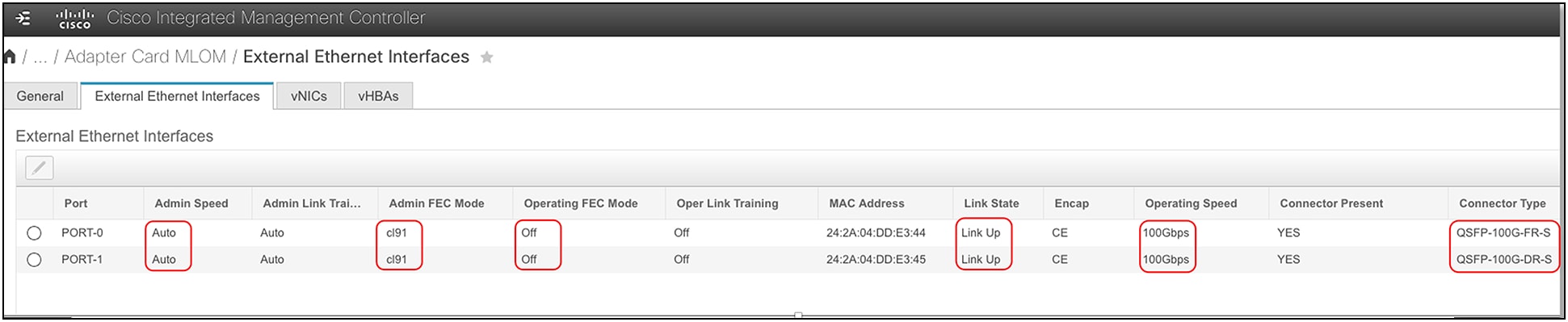
FEC settings for a VIC 100G adapter installed on UCS C-Series servers in standalone mode
For the link between a VIC and a switch/router to be “up,” the FEC settings must match on both ends. To arrive at common FEC settings on both the VIC and switch ports, the following factors must be taken into consideration:
● Exception: For 25G FEC settings, cl108 and cl91-cons16 are compatible. This is an exception to the rule that FEC needs to be matched at both the VIC and switch ports.
● Transceiver type: Some transceivers have minimum FEC requirements; for example, 25G-SR-S optics have a minimum FEC requirement of RS-FEC or CL91.
● Cable: Cables have a minimum FEC requirement depending on their length.
● Switch: FEC settings for 25/50/100/200G are based on IEEE and Ethernet-consortium standards. A switch or router can have FEC configuration options depending on the supported standards; also, the switch ports can have different default FEC settings, such as FC-FEC (CL74) or RS-FEC (CL91).
● VIC: On a VIC, the ports are set to RS-FEC or CL91 by default.
● Auto-Negotiation / Link Training (AN/LT):
◦ For 25G-Copper, Auto-Negotiation / Link Training (AN/LT) is supported and can be configured. The current default for 25G is “Admin” AN/LT “Auto,” which results in “Oper” AN/LT set to “Off.” If the “Admin” AN/LT is manually changed to “On,” the “Oper” AN/LT will be set to “On.” This will enable auto-detection of the FEC mode when the VIC port connects with SFP-H25G-CUxM cables and when the switch port is configured likewise.
◦ For 50G-Copper, Auto-Negotiation / Link Training (AN/LT) is supported and can be configured. The current default for 50G is “Admin” AN/LT “Auto,” which results in “Oper” AN/LT set to “On.” If the “Admin” AN/LT is manually changed to “Off,” the “Oper” AN/LT will be set to “Off.” This will disable auto-detection of FEC mode when the VIC port connects with SFP-50G-CUxM cables. So, to get the link up, the switch-port configuration should match the VIC for AN/LT configuration.
◦ For 40/100/200G-Copper, Auto-Negotiation / Link Training (AN/LT) is enabled by default and cannot be manually changed.
Due to the difference in the minimum required FEC across cables/transceivers and switches, the user needs to ensure that the FEC values are supported by the cables/transceivers and to configure them identically on the switch/router interfaces and VIC ports.
The following FEC configuration guidelines are for a VIC 15425/15427/15428 connected at 25Gbps to Cisco Nexus 9200/9300 switches using the standalone Cisco NX-OS build. But this can be used as a reference for other switches too. The FEC configuration on the switch port and on the VIC should be identical and configured to at least the minimum FEC or a value above it.
Table 4. FEC guidelines based on cable, transceiver, switch, and VIC
| Cable/transceiver PI |
Minimum FEC for cable/ transceiver |
Default on Cisco Nexus 9200/9300 (NX-OS) |
Default on VIC 15425/15427/15428 |
Minimum FEC configuration on switch and VIC |
| SFP-H25G-CU1M/1.5M/2M |
None |
CL74 (FC-FEC) |
CL91 (RS-FEC) |
None |
| SFP-H25G-CU2.5M/3M |
FC-FEC |
CL74 (FC-FEC) |
CL91 (RS-FEC) |
CL74 |
| SFP-H25G-CU4M/5M |
RS-FEC |
CL74 (FC-FEC) |
CL91 (RS-FEC) |
CL91 |
| SFP-25G-AOCxM |
FC-FEC |
CL74 (FC-FEC) |
CL91 (RS-FEC) |
CL74 |
| SFP-25G-SR-S |
RS-FEC |
CL74 (FC-FEC) |
CL91 (RS-FEC) |
CL91 |
| SFP-10/25G-CSR-S, 0-30M/50M, OM3/4 |
None |
CL74 (FC-FEC) |
CL91 (RS-FEC) |
None |
| SFP-10/25G-CSR-S, 30/50M to 70/100M, OM3/4 |
FC-FEC |
CL74 (FC-FEC) |
CL91 (RS-FEC) |
CL74 |
| SFP-10/25G-CSR-S, above 70/100M, OM3/4 |
RS-FEC |
CL74 (FC-FEC) |
CL91 (RS-FEC) |
CL91 |
| SFP-10/25G-LR-S |
RS-FEC |
CL74 (FC-FEC) |
CL91 (RS-FEC) |
CL91 |
| SFP-25G-SL |
RS-FEC |
CL74 (FC-FEC) |
CL91 (RS-FEC) |
CL 91 |
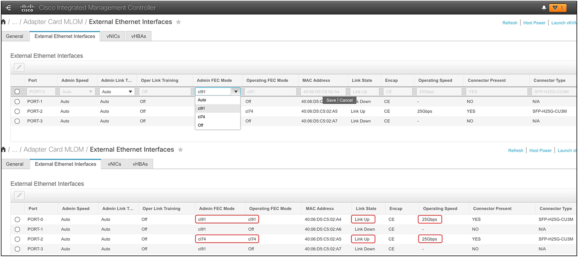
FEC configuration and validation for a VIC 15428 ports from Cisco IMC
Rack-server connectivity with VIC 15425,15427, 15428, 15235,15237, and 15238
VIC 15425/15427/15428 are quad-port 10/25/50G VIC cards designed for Cisco UCS C-Series rack servers. The card supports 10/25/50-Gbps Ethernet or FCoE.
By default, the VIC 15425/15427/15428 ports (1, 2) and (3, 4) are port-channel members of two separate hardware port-channels on the VIC ASIC. Hardware port-channel on the VIC 15425/15427/15428 provides link-level redundancy and higher bandwidth, and the OS can potentially see a maximum of 100Gbps vNICs on the adapter. For efficient load balancing, the traffic from the server is hashed across a VIC hardware port-channel using Layer-2, Layer-3, and Layer-4 fields in the packet. Note that this VIC hardware port-channel doesn’t support LACP.
In Cisco UCSM/IMM mode, there is no option to disable VIC hardware port-channel, so the VIC ports (1, 2) and (3, 4) are always in port-channel mode when connected to a fabric interconnect. While in standalone mode when the VIC 15425/15427/15428 is connected to a Cisco® or a third-party switch/router, the default hardware port-channel can be disabled from Cisco IMC.
Depending on whether the VIC hardware port-channel is enabled or disabled, the vNIC speed seen on the server will differ, and the behavior will be as follows:
● With the default port-channel enabled, each vNIC on a VIC 15425/15427/15428 will pin to a VIC hardware port-channel, and each vNIC will have the bandwidth equal to sum of the bandwidth of the active port-channel members combined. Please note that each VIC 15425/15427/15428 port supports either 10G, 25G, or 50G. Accordingly, the port-channel and vNIC speed could be 10G or 20G, 25G or 50G, and 50G or 100G, depending on whether it’s a 10G, 25G, or 50G link and how many ports are active.
● When disabling port channeling, each vNIC can pin to one of the four VIC external ports, and each vNIC will be 10G, 25G, or 50G, depending on the inserted transceiver.
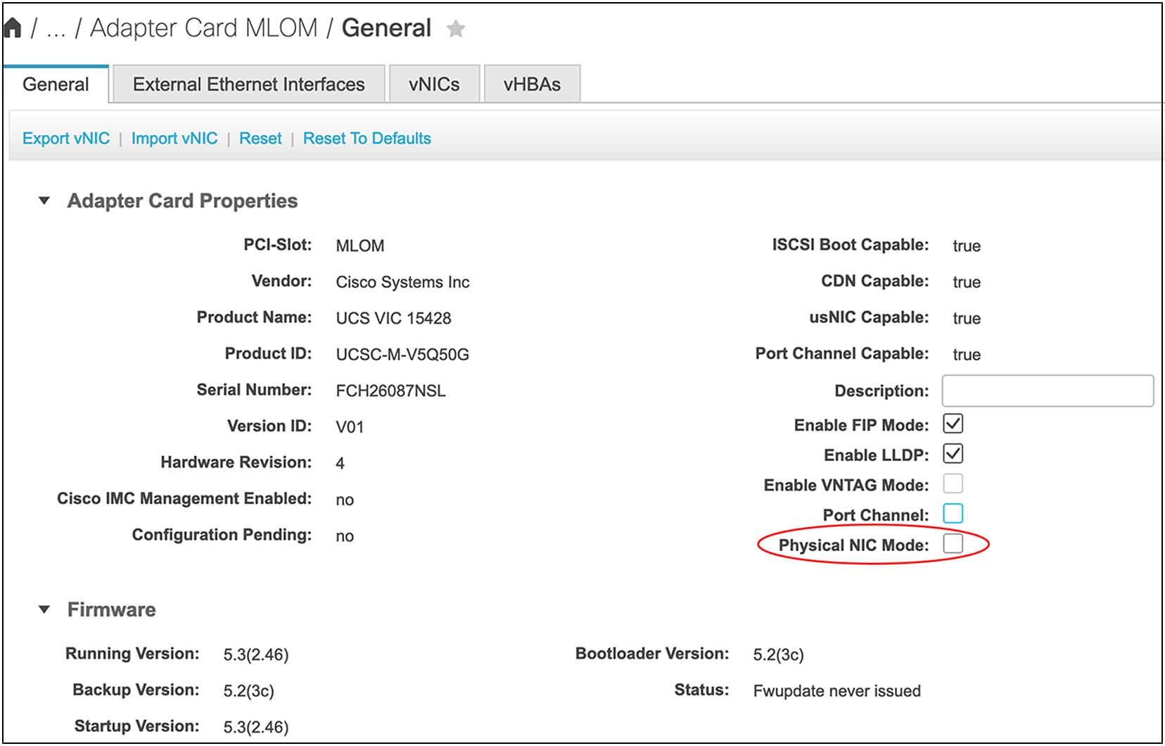
Disabling default port-channeling from Cisco IMC
The various connectivity options with VIC 15425/15427/15428 are as follows:
● In UCSM/IMM mode, connect VIC 15425/15427/15428 ports (1, 2) or both to fabric interconnect A (FI-A) and ports (3, 4) o both to fabric interconnect B (FI-B). When the VIC 15425/15427/15428s are connected to the fabric interconnects, the Cisco NX-OS software automatically provisions the port channels on fabric interconnects A and B.
● In standalone mode with port-channel mode enabled on VIC 15425/15427/15428, connect VIC ports (1, 2) or both to one top-of-rack (ToR) switch and ports (3, 4) or both to the other ToR switch. After both VIC ports in (1, 2) or (3, 4) are connected to their respective ToR switches, you will have to configure non-LACP port-channels on the ToR switches.
● In standalone mode with port-channel mode disabled, the VIC 15425/15427/15428 ports could be connected to ToR switches in any order.
The above connectivity options are detailed below. Please note that, in figures 54 and 55 below, the dotted lines represent optional connections or optional port-channel configurations. The connectivity options shown in the figures are applicable for VIC 15427/15428 (MLOM) and VIC 15425 (PCIe).
These figures depict physical connectivity and not the various NIC teaming options that are possible from an Operating System (OS) perspective.
VIC 15425/15427/15428 connectivity to fabric interconnects
When connected to a Fabric Interconnect (FI), the VIC ports (1, 2) and (3, 4) are always in port-channel mode and cannot be disabled. Ensure that the connectivity toward the FI is done taking into consideration hardware port-channel. Always connect ports (1, 2) to one fabric interconnect and ports (3, 4) to the other FI. When connecting two links per FI, the links become port-channeled automatically. One link per FI is also supported. VIC hardware port-channel cannot be disabled in FI-managed mode. vNIC/vHBA speeds can be 10/20/25/50G, depending on the number of active links and the transceiver type. There is no need to configure FEC or auto-negotiation; the link settings are auto-determined.
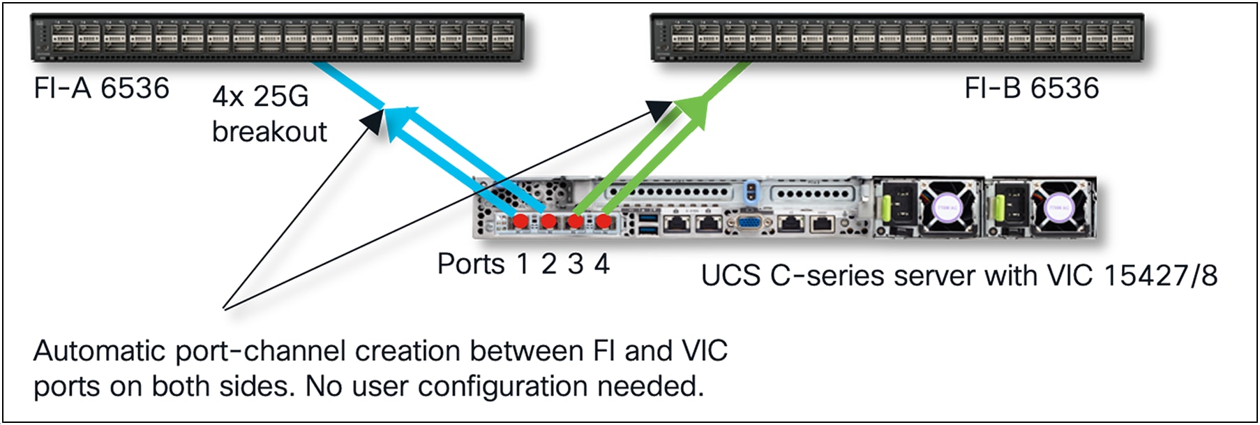
UCSM/IMM mode ports (1, 2) connect to one FI and ports (3, 4) to the other FI
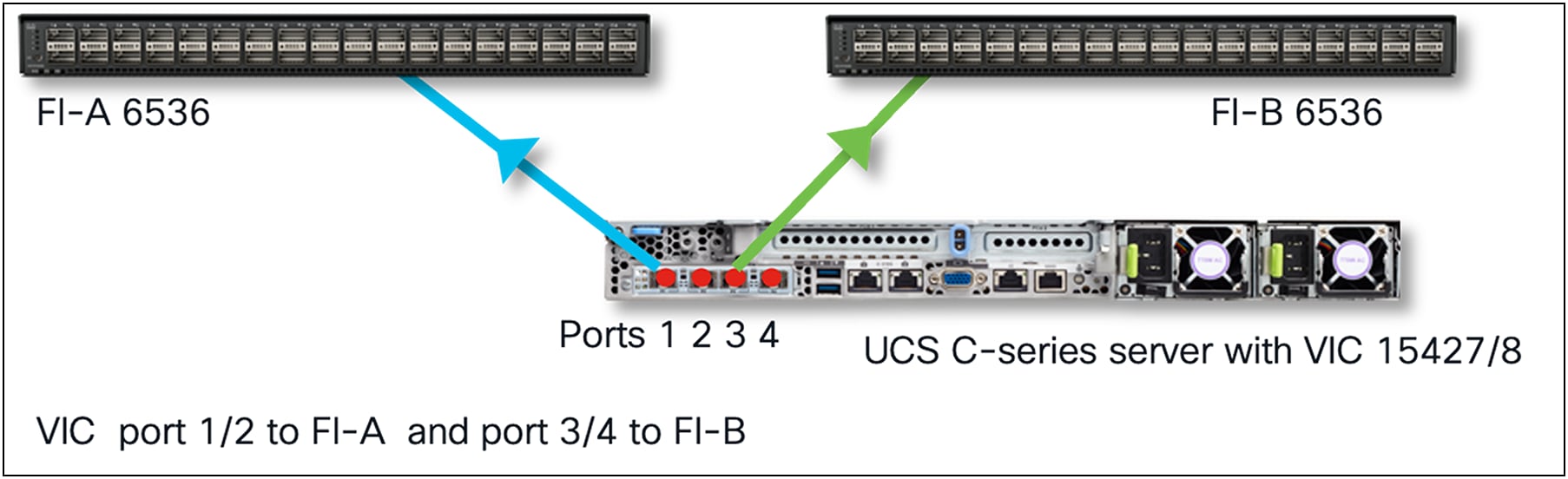
UCSM/IMM mode port 1 & 3 connected to FIs
VIC 15425/15427/15428 connectivity on standalone servers
In standalone mode or when the Cisco UCS server is managed through Cisco IMC, default port-channeling can be enabled or disabled. And depending on the choice, one needs to create the physical VIC-to-ToR switch connections as well as the OS teaming and upstream ToR switchport/port-channel configurations.
Default VIC port-channeling enabled on standalone servers
By default, VIC port-channel is enabled, and switch-dependent OS teaming/bonding from the server is possible only with a single link from VIC 15425/15427/15428 toward each ToR switch, as shown below. Ensure that VIC 15425/15427/15428 port 1 or 2 connects to one ToR switch and that VIC port 3 or 4 connects to the other ToR switch.
In this case, a common deployment is to have the ToR switches in a Multi-Chassis Trunking (MCT) pair, as shown in Figure 56. Examples of MCT are Virtual Port Channel (VPC) from Cisco, or multi-chassis link aggregation (mLAG) supported on third-party switches.
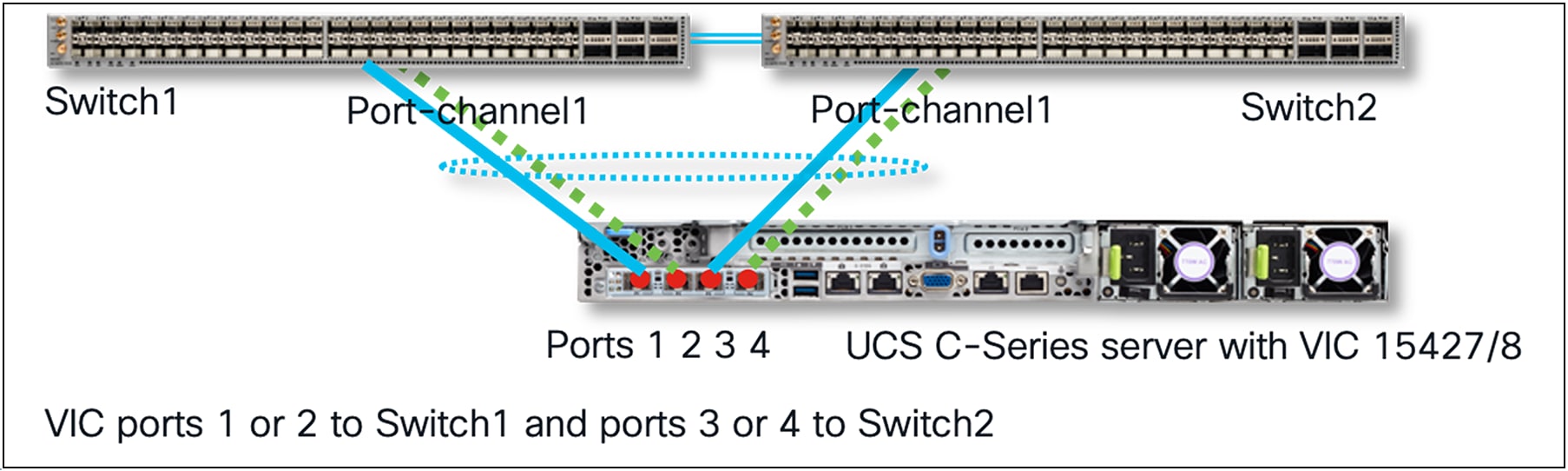
Standalone mode server connectivity with HW port-channels on VIC and MCT port-channel possible with single links to each ToR
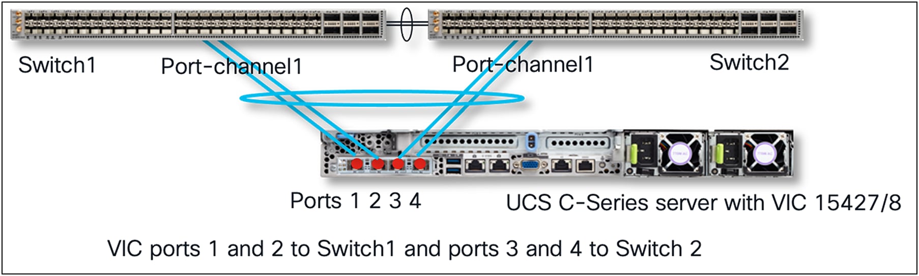
With VIC 15425/15427/15428 hardware port-channel enabled, if one wants to use all four ports of the VIC adapter, connect all four ports towards a ToR switch pair like in the diagram below. Ensure that VIC 15425/15427/15428 ports 1 and 2 connect to one ToR switch and ports 3 and 4 connects to the other ToR switch. Now, with dual links toward each ToR switch, and with default VIC hardware port-channel enabled, switch-dependent OS teaming from the server is not possible.
In this case, on each ToR switch, a non-LACP port-channel would have to be created. A VPC-like MCT port-channel spanning multiple ToR switches is not possible in this case.
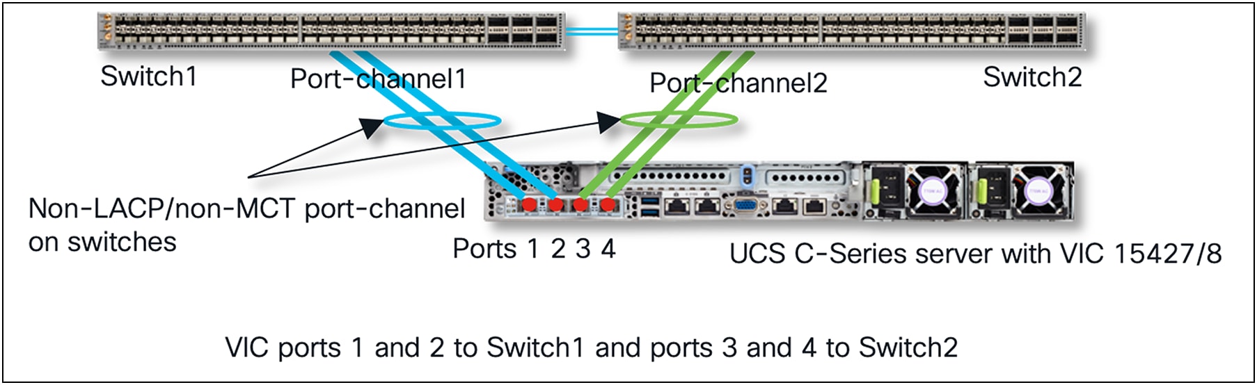
Standalone mode server connectivity with default port-channeling enabled and two links to each ToR
Default port-channeling disabled
With VIC 15425/15427/15428 hardware port-channeling disabled, a switch-dependent OS teaming/bonding on the server is possible across all ports with ToR switches in MCT. Switch-dependent port-channels can span across all four ports of the VIC. There is also no dependency on how the four ports of the VIC 15425/15427/15428 should be connected to the upstream ToR switches.
Standalone mode server connectivity with default port-channeling disabled
Priority tagging on VICs with standalone rack servers
VIC 15425/15427/15428/15235/15237/15238 have priority-tagging enabled for Quality of Service (QoS), and this priority tagging by the VIC could not be disabled in Cisco UCS VICs until Release 4.2(2). In the next section, the physical NIC-mode feature is explained; this feature can disable priority-tagging in the VIC. Meanwhile, with the default priority-tagging enabled, the untagged traffic from the server will always be sent by the VIC with a VLAN tag “0” for CoS to the upstream switch/router.
This priority tagging needs to be taken into consideration when connecting the VIC in a standalone rack server, to a third-party switch, or to a non-Cisco Nexus switch, because the upstream ToR switch/router that the VIC connects to may or may not support priority-tagging.
Before going into details of how to handle this, here are some additional configuration options for vNICs on the Cisco IMC that you should be aware of:
● By default, in standalone mode, no “default-VLAN” is configured under the vNIC properties in Cisco IMC. And in this case the untagged traffic from the server will be tagged with VLAN 0 and sent toward the upstream ToR switch/router.
● If “default-VLAN” is configured under the vNIC, then the untagged traffic from the server will be tagged with that configured VLAN ID and sent to the upstream ToR switch/router.
The following behavior is to be expected, depending on whether priority tagging is supported or not on the upstream switch:
● If the upstream switch supports priority tagging, then the upstream switch’s port and the vNIC should work seamlessly. Please note that, by default, the vNICs are in trunk mode, and the “Default-VLAN” under vNIC properties is none.
● If the upstream switch doesn’t support priority tagging, then the vNIC must be configured as a trunk with a default VLAN. With a default VLAN configuration on the vNIC, the untagged traffic from the server will be sent on this VLAN ID by the VIC toward the upstream switch. And on the upstream switch port, this default VLAN on vNIC should be configured using a “switchport trunk native VLAN <vlan-id>” in the Cisco NX-OS equivalent configuration.
Please note that untagged packets from the server, such as LACP, which are to be processed by the supervisor or control plane on the switch or router, are sent by the VIC in “VLAN-0” or the “default VLAN” of the vNIC if it is configured. So even if some switches or routers support priority tagging, they ignore the processing of the control-plane-bound packets on this VLAN. Also, in these cases, LACP cannot be used.
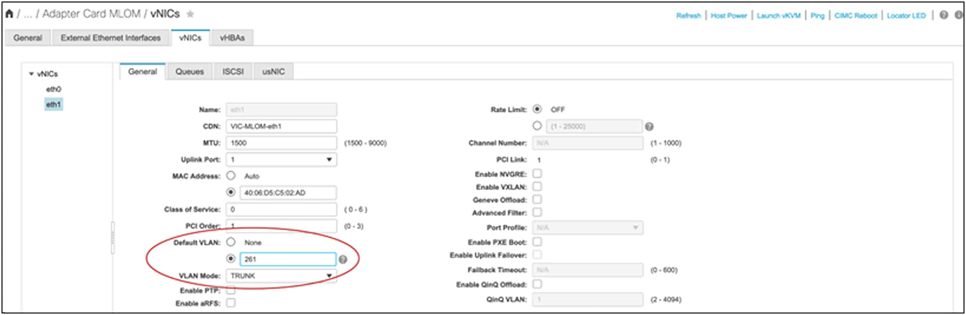
Default VLAN configuration under vNIC from Cisco IMC
Physical NIC mode on VICs in standalone rack servers
The previous section described the default priority-tagging behavior in VICs. For switches or routers that don’t support the full priority-tagging implementation, such as Cisco Nexus switches, this creates some challenges, especially with LACP packets. Hence, for supporting connectivity with various ToR switches or routers with VIC in standalone rack servers, the “Physical NIC Mode” feature was added.
Physical NIC mode, essentially, sets a VIC in passthrough mode. This doesn’t require configuring VLANs for sending traffic from the host. Depending on 2-port or 4-port VIC adapters, those ports are available on the host in the same way as those of a standard network adapter.
With physical NIC mode, the VIC will behave as a passthrough network interface card. The following are the requirements for VICs to run in physical NIC mode:
● Supported only in Cisco UCS standalone rack servers with VIC 1400/14000 and VIC 15000 series adapters.
● Default VIC port-channeling must be disabled on VIC 15425/15427/15428.
● VNTAG mode, LLDP on external interface, and FIP mode must also be disabled.
● iSCSI protocol and FC protocol through vHBA is not supported. They require FIP/LLDP support which needs to be disabled for physical NIC mode.
● Users cannot create vNICs in addition to available system default vNICs (four vNICs for VIC 15425/15427/15428 and two for VIC 15235/15237/15238).
With this feature, vNICs can be enabled for access or trunk mode (*) when connecting to any switch or router, and the untagged traffic will be carried as is without any VLAN-0 tag; with trunk mode, the tagged packet will carry the VLAN-ID tag. Besides the above-mentioned restrictions, some features not included with physical NIC mode are SR-IOV, RoCEv2, GENEVE offload, and usNIC.
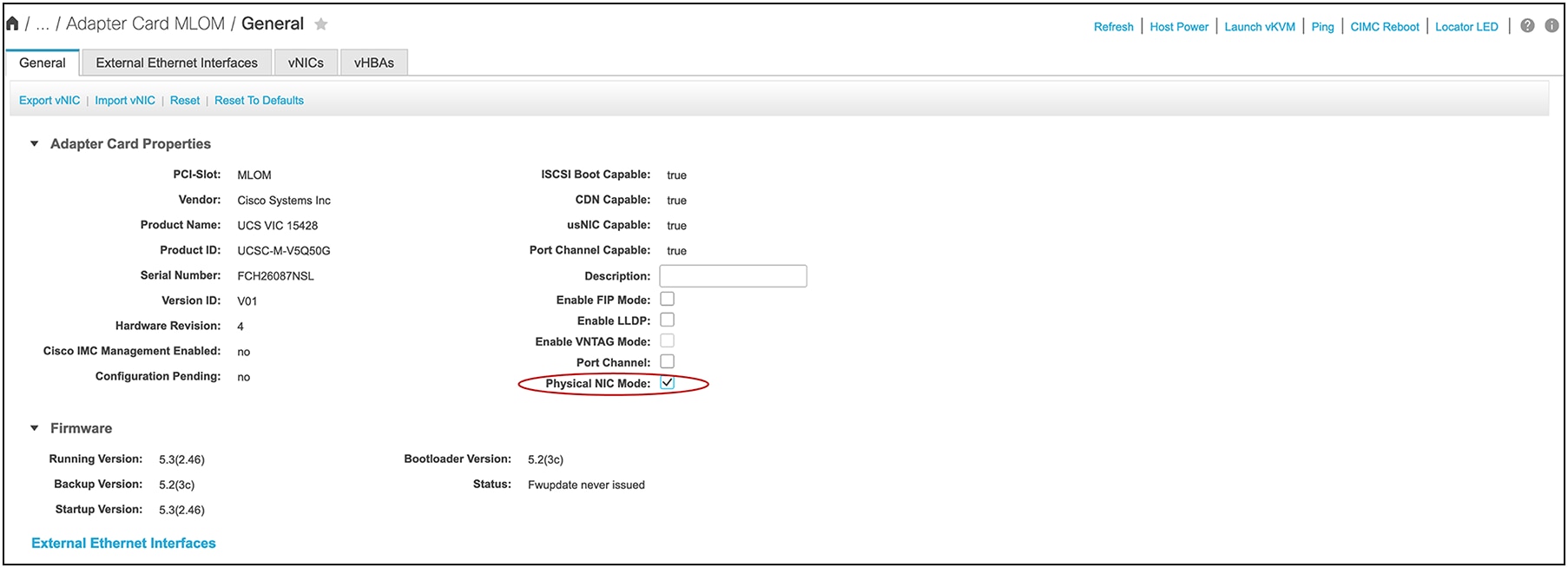
Physical NIC mode configuration in Cisco IMC
Read more about Cisco UCS products: https://www.cisco.com/c/en/us/products/servers-unified-computing/index.html.
Read more about the Cisco UCS VIC 15000 Series: https://www.cisco.com/c/en/us/products/collateral/interfaces-modules/unified-computing-system-adapters/ucs-vic-15000-series-ds.html.
Read move about Cisco Unified Computing System Adapters: https://www.cisco.com/c/en/us/products/interfaces-modules/unified-computing-system-adapters/index.html.
https://www.cisco.com/c/en/us/products/collateral/servers-unified-computing/ucs-b-series-blade-servers/ucs-m7-platforms-wp.html .