Cisco Secure DDoS Edge Protection Quick Start and Installation Guide
Available Languages
Cisco Secure DDoS Edge Protection® is a software solution that stops cyberattacks at the service provider network edge. The Cisco Secure DDoS Edge Protection solution consists of two (2) components, a controller and one (1) or more detectors. A Cisco Secure DDoS Edge Protection detector can be deployed on Cisco IOS® XR. When a detector is deployed on the Cisco® NCS 540 routers, Cisco Secure DDoS Edge Protection detects and mitigates distributed-denial-of-service (DDoS) attacks at the cell site router. By moving DDoS protection to the network edge, service providers are able to meet the sub-10-ms latency requirements of 5G applications and ensure customer quality of experience (QoE).
This quick start guide (QSG) is intended to help customers download, install, and start using Cisco Secure DDoS Edge Protection.
Minimum virtual machine (VM) requirements for installing the Cisco Secure DDoS Edge Protection controller:
● CPU: 4vCPU
● Memory: 8 GB
● Storage: 50 GB
● 1 network interface
The VM can be deployed on VMware or KVM hypervisors.
The VM is based on a Linux Ubuntu 20.4 LTS distribution with Docker and SSH server installed. There is an OVA image that can be shared. Please reach out to your Cisco systems engineer for the file.
Minimum VM requirements for installing the Cisco Secure DDoS Edge Protection detector:
● CPU: 2vCPU
● Memory: 8 GB
● Storage: 50 GB
The detector VM will be installed on Cisco IOS XR such as the NCS 540.
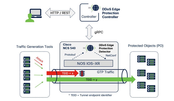
The Edge Protection solution has two main parts. The detector runs on the edge router running IOS XR and collects traffic flow information from specific interface on the router. The controller is a remote management system that controls the operation, monitors, and analyzes the information provided by the detector.
DDoS detection and mitigation functions are implemented on a virtual Docker container as a microservice application. The function runs independently on the designated edge router.
The controller provides a central management function and a user Interface to manage a collection of detectors. The controller includes a GUI dashboard that presents information for real-time attacks for detector visibility, forensics, and threat intelligence analysis.
The following is an illustration of the current Edge Protection topology integrated with a Cisco NCS 540 router:
Demo setup – Cisco Secure DDoS Edge Protection
4. Downloading Cisco Secure DDoS Edge Protection software
There are two (2) software components, the OVA image, which is the Linux virtual machine, and the tar file that contains the controller software to be installed.
Download the OVA file with the link provided by your Cisco sales engineer.
5A. Deploy the OVA on hypervisor
Please note the steps provided are for VMware.
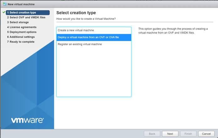
From your hypervisor, click on “Create/Register VM,” select “Deploy a Virtual Machine” from an OVF or OVA file, and then click “Next.”
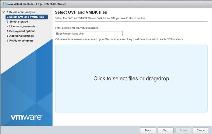
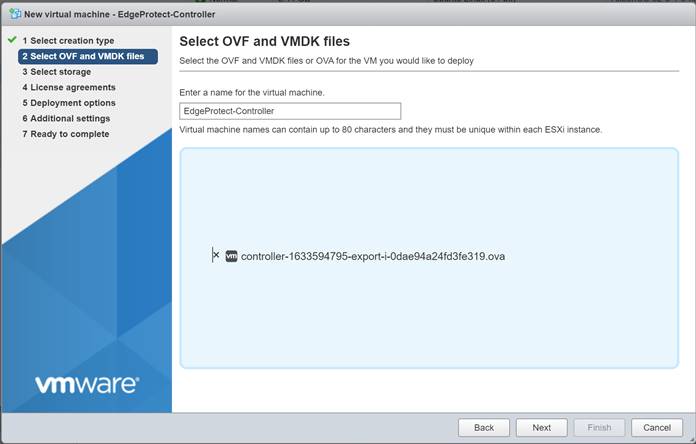
Enter a name for the new VM such as “EdgeProtect-Controller,” and then click inside the light blue box to bring up the File Explorer and select the OVA file.
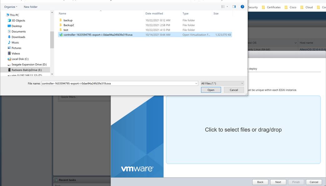
Select the file and click Open
Then click next
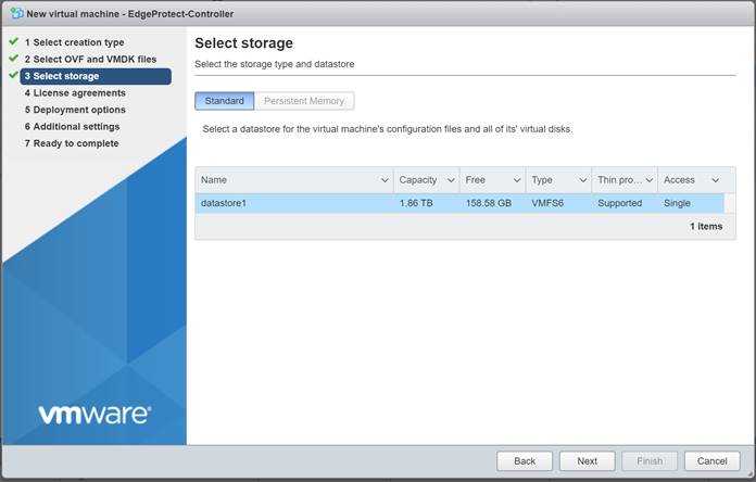
Click Next on the following screen.
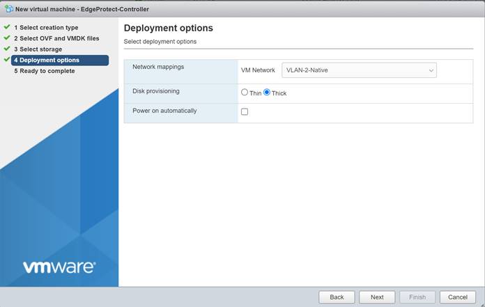
Select the appropriate VM network that you want your controller to connect to. In our lab, we used VLAN-2-Native. Disk provisioning should be thick to ensure that enough disk space is reserved for the VM. Uncheck the “Power on Automatically” option and then click “Next.”
Then click “Finish.”
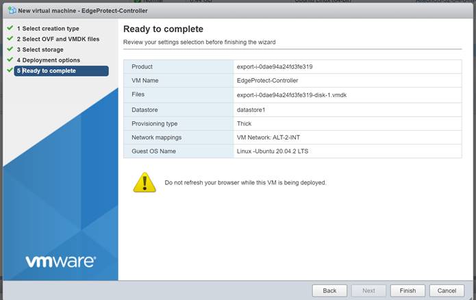
Wait until OVA deployment is complete.
![]()
![]()
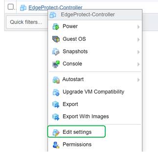
Once complete, right click on the VM and click on “Edit Settings.”
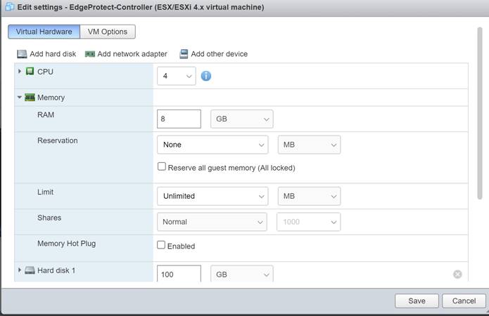
Change the CPU to 4 and Memory to 8 GB, and then click “Save.”
Power on the VM.
Once the controller is powered on, connect to the console. The username and password will be provided by your Cisco sales engineer.
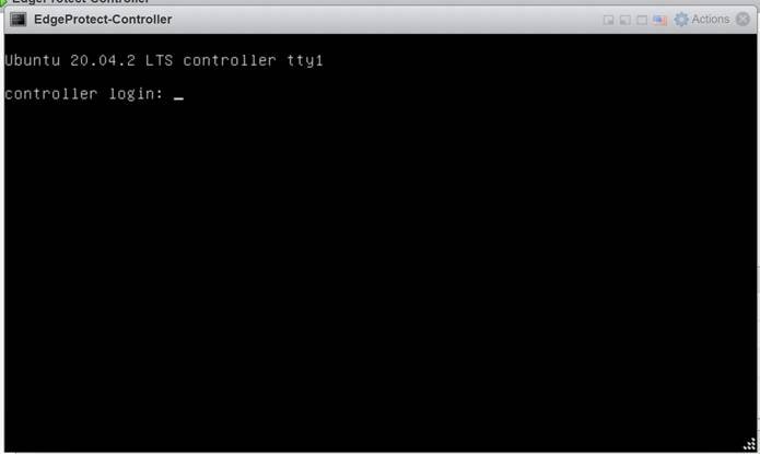
Log on using the credentials provided by your Cisco sales engineer.
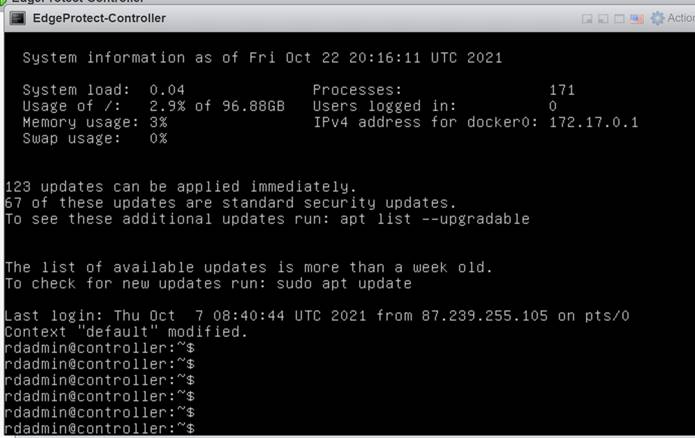
Discover the name of the controller interfaces by running the command ip add, as this may vary per installation.
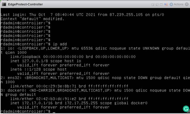
Look for the interface that begins with “ens.” In this example, we see “ens32.” This information will be needed to configure the network settings.
Change directories to the /etc/netplan:
cd /etc/netplan
Find the yaml file by running the ls command.

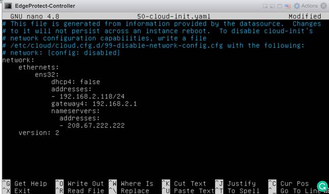
Edit the yaml file to reflect the static IP address for the controller with the default gateway and your DNS servers. In this example, we will set the IP address to 192.168.2.118/24 with a default gateway of 192.168.2.1 and the Cisco Umbrella® DNS server of 208.67.222.222.
sudo nano 50-cloud-init.yaml
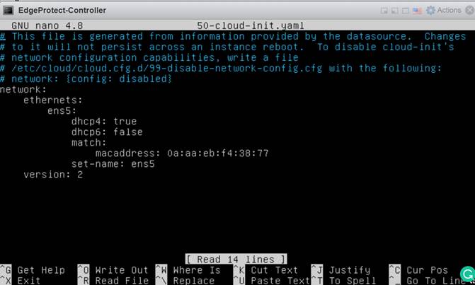
This is what it looks like before you edit it.
Below is the newly configured yaml file, with the correct interface name (ens32) and network settings.
Press “Control + X” to exit, and then press “Enter” to confirm the save.
Apply the new network setting using the following command:
sudo netplan apply

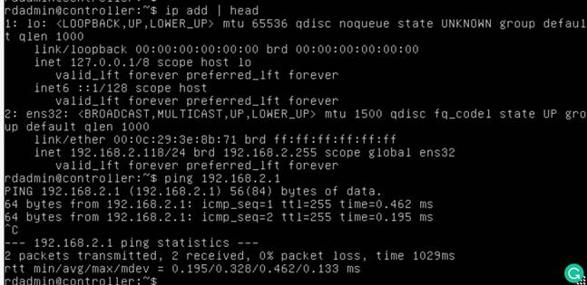
Validate that the configuration took effect by running the command ip addr | head again and validating that the interface is configured correctly. Also make sure that your network is reachable by pinging a known valid and pingable address such as your default gateway.
Installing the controller software on the VM.
Download the controller .tar file using the provided wget command. A link to the .tar file will be provided in a separate email:
$ wget -O “controller-<version x_y_z>.tar.gz” “https://<DOWNLOAD LINK>”
File can also be copied using SCP onto the VM if direct internet access is not available.
1. Copy the .tar file to /tmp/ with $ cp controller-<version x_y_z>.tar.gz /tmp/.
|
$ cd /tmp $ tar –xvf controller<version x_y_z>.tar.gz |
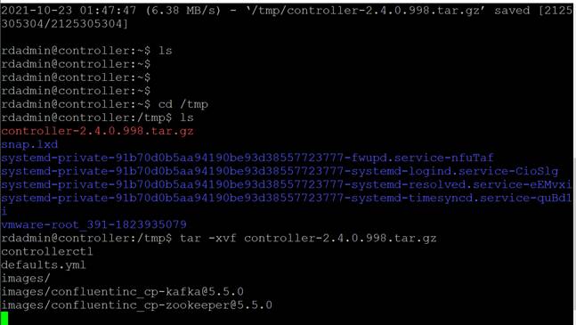
Run the deployment script:
$ ./scripts/deploy.sh
Note
The deployment process will run a set of validation tests to confirm that the minimum requirements are met and that no errors were encountered.
Follow the steps below to configure the controller. At the end of this process, you will be able to connect to the controller management system with your web browser: http://<controller_hostname> or http://<controler_ip>.nip.io
To access the controller, a valid hostname is required that is resolvable via DNS. If you do not have access to create a resolvable hostname, the nip.io service can be used, but you must manually add the client IP to hostname mapping in the client machine’s hosts file that is by default located in C:\Windows\System32\ drivers\etc. Administrator access to the client machine is required to modify the hosts file.
1. Verify that the controller directory exists:
|
$ cd /opt/app/controller $ ls –lah |
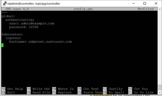
2. Create a file named config.yml in the /opt/app/controller directory and modify the hostname to an applicable URL.
|
$ nano config.yml
|
Use the configuration below as a reference for the config.yml. Copy the example file to config.yml and modify it based on your setup.
Note: Be sure to use the right yaml format and two spaces for indentation.
The hostname MUST be a valid DNS hostname that can be reached from your browser. It is possible to use the nip.io services and set the internal IP or add the URL to your local hostname file with a matching IP. More information on the nip.io service can be found at https://nip.io.
Reference example for config.yml file using the nip.io:
|
--- global: authentication: user: admin@example.com password: 12345
kubernetes: ingress: hostname: 192.168.2.118.nip.io |
Reference example for config.yml file using the hostname:
3. Start the controller service.
$ ./controllerctl start
4. Verify that the controller services are running with the command:
|
$ cd /opt/app/controller $ kubectl get pods |
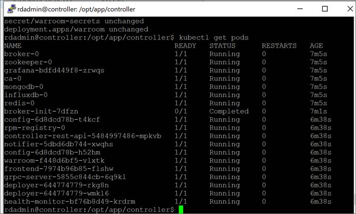
Make sure you are in the correct namespace. If not, run:
sudo kubectl config set-context --current --namespace controller
5. Open your browser and use the URL set in hostname: http://<controller-hostname> or http://<controller_ip>.nip.io
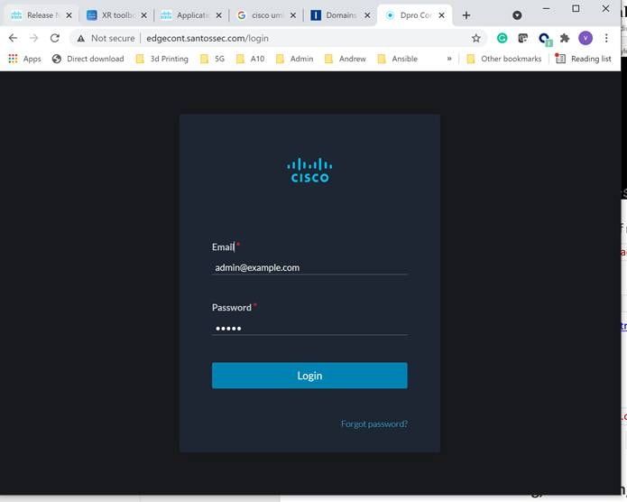
6. Log in with the default user admin@example.com and password 12345 or with the user and password configured in the config.yml file.
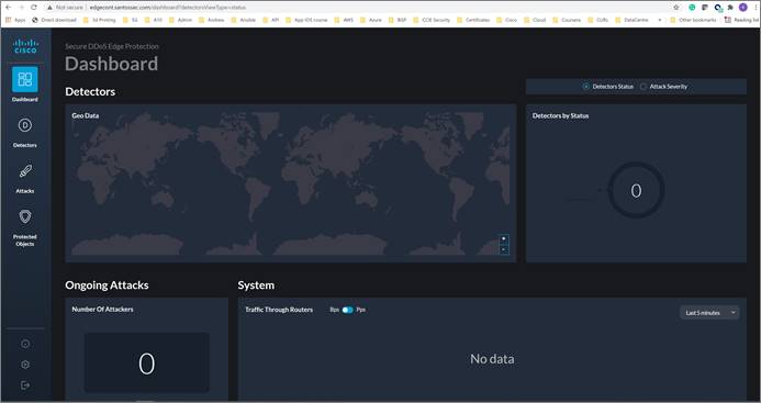
Controller installation is now complete.
By default, the controller is provided with a 30-day evaluation license.
To add or view the license, go to Settings ![]() (bottom left) and then click on the licensing tab.
(bottom left) and then click on the licensing tab.
To obtain a new license, reach out to your Cisco sales engineer and provide them with the controller MAC address:
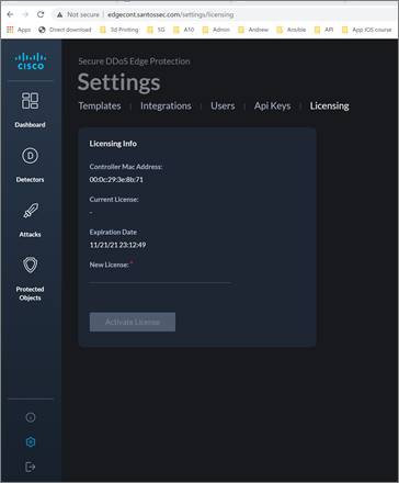
To add an emulator detector or a real detector, follow the same steps. Differences include using either the controller’s IP address and SSH credentials or using the router’s IP addresses and credentials.
Prior to adding an emulator detector, the emulator JSON file may need to be edited with the correct emulator filename.
To find an available emulator file, go to the following directory on your controller CLI.
|
$ cd /opt/app/controller/rpm $ ls |

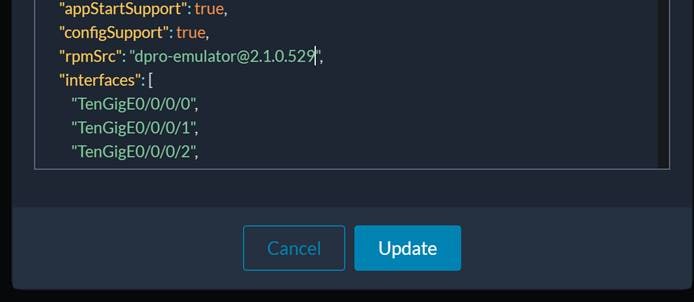
Copy the name of the “dpro-emulator…” In this case, it is dpro-emulator@2.1.0.529.
Go to Settings ![]() (bottom left) and then click on the “Templates” tab. Then click on the
(bottom left) and then click on the “Templates” tab. Then click on the ![]() on the right-hand side of the emulator default.
on the right-hand side of the emulator default.

Select “Edit JSON.”
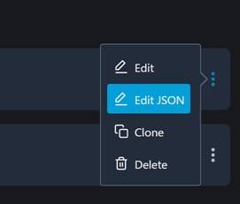
Scroll down through the file until you reach the line that starts with “rpmSrc.”
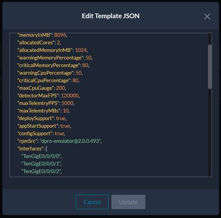
Edit the line with the correct file name capture in the rpm directory. Then click “Update.”
Click on the “Detectors” icon ![]() and then click on the plus sign
and then click on the plus sign ![]() on the top-right side.
on the top-right side.
Then select “Add Detector.”

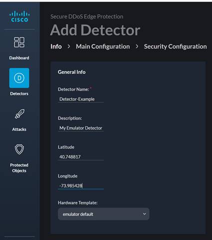
On the Info page, fill in the fields with the appropriate information. In this example, we use the following:
● Detector Name: Detector-Example
● Description: My Emulator Detector
● Latitude: 40.748817
● Longitude: -73.985428
● Hardware Template: emulator default
Click on the “Main Configuration” tab.
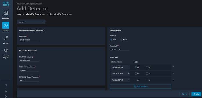
Use the IP address of the controller for the IP Address, NETCONF Server IP, and the Exporter IP. Also use the SSH username and password of your controller, as this is an emulator.
Uncheck the TenGigE0/0/0/2 rx box and then click “Create.”

After one to two minutes, you should see the emulator detector up.

The process is now complete to add the emulator detector.
● Cisco Secure DDoS Edge Protection on DevNet: https://developer.cisco.com/docs/secure-ddos-edge-protection
● Cisco Secure DDoS Edge Protection AAG: https://www.cisco.com/c/en/us/products/collateral/security/secure-ddos-edge-protection-aag.pdf
● Cisco Secure DDoS webpage: www.cisco.com/go/secure-ddos
● Edge Protection Support email alias: secure-ddos-edge-protection@external.cisco.com
 Feedback