Deployment Guide for Cisco Office-in-a-Box with VMware Horizon View
Available Languages
NOTICE ALL STATEMENTS, INFORMATION, AND RECOMMENDATIONS IN THIS MANUAL ARE BELIEVED TO BE ACCURATE BUT ARE PRESENTED WITHOUT WARRANTY OF ANY KIND, EXPRESSED OR IMPLIED. USERS MUST TAKE FULL RESPONSIBILITY FOR THEIR APPLICATION OF ANY PRODUCTS.
THE SOFTWARE LICENSE AND LIMITED WARRANTY FOR THE ACCOMPANYING PRODUCT ARE SET FORTH IN THE INFORMATION PACKET THAT SHIPPED WITH THE PRODUCT AND ARE INCORPORATED HEREIN BY THIS REFERENCE. IF YOU ARE UNABLE TO LOCATE THE SOFTWARE LICENSE OR LIMITED WARRANTY, CONTACT YOUR CISCO REPRESENTATIVE FOR A COPY.
The Cisco implementation of TCP header compression is an adaptation of a program developed by the University of California, Berkeley (UCB) as part of UCB's public domain version of the UNIX operating system. All rights reserved. Copyright © 1981, Regents of the University of California.
NOTWITHSTANDING ANY OTHER WARRANTY HEREIN, ALL DOCUMENT FILES AND SOFTWARE OF THESE SUPPLIERS ARE PROVIDED "AS IS" WITH ALL FAULTS. CISCO AND THE ABOVE-NAMED SUPPLIERS DISCLAIM ALL WARRANTIES, EXPRESSED OR IMPLIED, INCLUDING, WITHOUT LIMITATION, THOSE OF MERCHANTABILITY, FITNESS FOR A PARTICULAR PURPOSE AND NONINFRINGEMENT OR ARISING FROM A COURSE OF DEALING, USAGE, OR TRADE PRACTICE.
IN NO EVENT SHALL CISCO OR ITS SUPPLIERS BE LIABLE FOR ANY INDIRECT, SPECIAL, CONSEQUENTIAL, OR INCIDENTAL DAMAGES, INCLUDING, WITHOUT LIMITATION, LOST PROFITS OR LOSS OR DAMAGE TO DATA ARISING OUT OF THE USE OR NABILITY TO USE THIS MANUAL, EVEN IF CISCO OR ITS SUPPLIERS HAVE BEEN ADVISED OF THE POSSIBILITY OF SUCH DAMAGES.
Access Registrar, Aironet, AsyncOS, Bringing the Meeting to You, Catalyst, CCDA, CCDE, CCDP, CCENT, CCIE, the CCIE logo, CCIP, CCNA, CCNP, CCSP, CCVP, Cisco, the Cisco logo, Cisco Eos, Cisco IOS, Cisco Lumin, Cisco Nexus, Cisco Press, Cisco Store, Cisco StadiumVision, Cisco Systems, the Cisco Systems logo, Cisco Systems Capital, Cisco TelePresence, Cisco Unity, Cisco WebEx, Collaboration Without Limitation, EtherFast, EtherSwitch, Event Center, Fast Step, Follow Me Browsing, FormShare, GigaDrive, HomeLink, Internet Quotient, IOS, iPhone, iQuick Study, IronPort, the IronPort logo, LightStream, Linksys, MediaTone, MeetingPlace, MeetingPlace Chime Sound, MGX, Network Registrar, Networkers, Networking Academy, PCNow, PIX, PowerPanels, ProConnect, ScriptShare, SenderBase, SMARTnet, Spectrum Expert, StackWise, The Fastest Way to Increase Your Internet Quotient, TransPath, WebEx, the WebEx logo, and Welcome to the Human Network are registered trademarks; Changing the Way We Work, Live, Play, and Learn is a trademark of Cisco Systems, Inc. and/or its affiliates in the United States and certain other countries.
All other trademarks mentioned in this document or website are the property of their respective owners. The use of the word partner does not imply a partnership relationship between Cisco and any other company. (0809R)
Deployment Guide for Cisco Office-in-a-Box with VMware Horizon View
Copyright © 2014 Cisco Systems, Inc. All rights reserved.
About the Author
 Tony Banuelos, Technical Marketing Engineer, Services Routing Group, Cisco
Tony Banuelos is a technical marketing engineer for the Services Routing group, and is responsible for the Cisco UCS E-Series and the on-boarding of virtual applications like VDI. He is also responsible for Cisco Unified Communications services that run on Cisco Integrated Services Routers (ISRs).
Introduction
The modern workplace continues to evolve, and improved mobility is essential. New bring-your-own-device (BYOD) and virtual desktop infrastructure (VDI) initiatives try to meet the need for an increasingly agile, productive, and collaborative workforce. Most VDI adopters have found that deploying VDI at the branch or remote office is a challenge. When virtual desktops are centralized so that users access them across the WAN, the user experience is poor, and the business continuity must rely on the WAN. Cisco® Office-in-a-Box offers a way to easily collapse enterprise branch office or retail store IT services into a single box. These services include VDI where the virtual desktops are hosted locally on a Cisco Unified Computing System™ (Cisco UCS®) E-Series server. Cisco UCS E‑Series servers provides an excellent user experience (LAN-based connectivity) and removes reliance on the WAN for business continuity.
This guide shows how to deploy a VMware Horizon View VDI solution to a Cisco next-generation WAN branch office. This guide explains what the benefits are, how to deploy the solution that combines the Cisco Integrated Services Router Generation 2 (ISR G2) platform with Cisco UCS E-Series servers, and where to find additional information to make the deployment a success.
What Problems Does Cisco Office-in-a-Box Solve?
For the mobile branch office or the standard branch office, bandwidth and latency requirements for VDI come at a premium cost. When you host end-user VDI virtual machines and applications on the local Cisco UCS E-Series server, all mission-critical applications run on site. When these applications run on site, you need not depend on the WAN to deliver critical services. Also, the user experience is greatly improved because access to the VDI session remains within the local office. Now with Horizon View Agent Direct-Connection, the branch user can access a virtual desktop directly, without a connection to the VMware Horizon View connection server. In the case of a data-center-to-branch-office deployment model, the administration of the VDI pool for the branch can be managed centrally through the VMware Horizon View Connection server, but users do not require network connectivity to the connection server to access their hosted desktops. The solution can be delivered within a single Cisco ISR G2 box, which greatly reduces the number of devices that must be at the branch office or retail store to deliver the required services. One box means that on-site management is simpler, and the box can be managed remotely. Two deployment models are supported with VMware Horizon View 5.2. One model is fully distributed, where the VDI management infrastructure and VDI sessions are hosted within the Cisco UCS E-Series server. In the second model, The VDI management infrastructure is centralized at the data center, but VDI sessions are distributed across branch offices hosted in Cisco UCS E-Series servers.
Which Organizations Benefit from Cisco Office-in-a-Box?
Cisco Office-in-a-Box can help organizations that are considering VDI to centralize desktop services. These organizations want to take advantage of the many benefits that VDI offers but do not want to upgrade their WAN to support VDI sessions, or they do not want to rely on WAN connectivity for users to access mission-critical applications.
Cost Effectiveness of Cisco Office-in-a-Box
The Cisco Office-in-a-Box solution provides a way to collapse all services that businesses require into a single box, which results in easier management of services, a much smaller device footprint on site, and lower TCO. This product is part of a multiphased approach of the Cisco VDI Cloud connector strategy to address business continuity and end-user experience. The Cisco UCS E-Series servers and the Cisco ISR G2 are built for enterprise-grade performance with a service life expectancy longer than that of commercially available servers and routers. Also, the Cisco ISR G2 and Cisco UCS E-Series solutions are covered under one Cisco SMARTnet® services contract, which provides expert technical support, flexible hardware coverage, and smart, proactive device diagnostics. Your IT staff has anytime access to Cisco engineers in the Technical Assistance Center (TAC) and an extensive range of resources, tools, and training.

Cisco Office-in-a-Box: How Does It Work?
The Cisco ISR G2 platform runs Cisco IOS® Software, which delivers an array of IT services such as these:
● Network routing
● IP PBX (Cisco Unified Communications Manager Express/Survivable Remote Site Telephony
[Cisco Unified SRST])
● Public switched telephone network (PSTN) connectivity
● WAN acceleration (Cisco Wide Area Application Services [Cisco WAAS])
● Remote access
● Network Address Translation (NAT)
● Cisco IOS firewall
● DHCP
The Cisco UCS E-Series x86 server modules can be inserted into Cisco ISR G2 platforms and can deliver additional services. (See the Cisco UCS E-Series data sheet for a platform compatibility matrix.) The Cisco UCS E-Series supports VMware ESXi 5.0 and 5.1, which allows you to virtualize multiple applications and services. One such service is the VMware Branch Office Desktop. The Cisco UCS E160D server module can support up to 48 GB of memory, and it runs on a 6-core Intel processor with hyperthreading support, which makes it a 12-core server. Depending on the Cisco ISR G2 platform, you can insert more Cisco UCS E-Series modules if more computing power is necessary. Additional modules can expand the virtual desktop solution or add applications such as video surveillance, digital signage, or virtualized Cisco applications like Cisco Virtual WAAS (vWAAS).
The Cisco ISR G2 motherboard and the Cisco UCS E-Series blades interconnect through a backplane 1 Gigabit Ethernet switch, which allows for virtual data traffic to traverse the router services and set policies. The Cisco ISR G2 supports 2 or 3 Gigabit Ethernet ports. One of these ports can be used to connect to an Internet telephony service provider (ITSP) connection to provide Internet connectivity to the virtual desktops, and access to the Internet can be managed through policies set on the router. Also, firewall services can be turned on to prevent incoming attacks from the Internet.
A second Gigabit Ethernet port on the router can be used for management. The Cisco UCS E-Series server supports the Cisco Integrated Management Controller (a BMC feature) to allow configuration, administration, and monitoring of server resources via a web-based GUI. The Cisco UCS E-Series blades have been validated by VMware for its Branch Office Desktop through the Rapid Desktop deployment program. The VMware Rapid Desktop deployment solution allows easy deployment and configuration of a VMware Horizon View Branch Office Desktop solution and delivers the benefits and services of Cisco ISR G2 technologies within a single box. (VMware Horizon View was formerly known as VMware View.)
A third Gigabit Ethernet port on the router can be used for voice services. The Cisco ISR G2 supports Cisco Unified Communications Manager Express, which is an IP PBX application and supports Cisco IP phones or analog phones using Cisco analog voice/WAN interface card (VWIC) modules. For PSTN, access to the Cisco ISR G2 supports a variety of PSTN access VWIC modules (T1 PRI, T1 CAS, FXO, and BRI) and supports Session Initiation Protocol (SIP) trunking to SIP service providers.
For more information about Cisco Unified Communications Manager Express, visit: http://www.cisco.com/en/US/products/sw/voicesw/ps4625/index.html.
Also, the Cisco ISR G2 platforms support Ethernet switch service modules that insert into a service module slot to provide network access to VDI clients and other network devices, such as IP phones. For more information about the Cisco ISR G2, visit: http://www.cisco.com/en/US/prod/collateral/routers/ps10536/data_sheet_c78-553980_ps10537_Products_Data_Sheet.html.
Where Cisco Office-in-a-Box Fits in the Deployment
Cisco Office-in-a-Box with VMware Horizon View can be centrally managed or fully distributed depending on how an organization needs to manage its VDI solution and whether the remote offices are connected back to the headquarters’ data center.
Figure 1 shows a fully distributed VMware Horizon View solution.

With a fully distributed VDI deployment, each remote office hosts a VMware Horizon View management infrastructure that consists of a VMware Horizon View connection server, Active Directory (AD) server, vCenter/View composer server, and SQL Express server. Table 1 lists virtual machine roles and configurations. Figure 2 shows the logical grouping of the required virtual machines.
Table 1. Virtual Machine Roles and Configurations
| Virtual Machine Role |
Virtual Machine Specification |
Notes |
| Microsoft Active Directory Domain Controller |
1 virtual CPU (vCPU) with 2048 MB of RAM and Microsoft Windows Server 2008 R2 64-Bit Standard Edition |
Microsoft Active Directory domain controller 1 |
| VMware vCenter VMware Horizon View Composer Microsoft SQL Server 2008 R2 Express |
2 vCPUs with 2048 MB of RAM and Microsoft Windows Server 2008 R2 64-Bit Standard Edition |
VMware vCenter and Composer and Microsoft SQL services |
| View Connection Manager |
2 vCPUs with 2048 MB of RAM and Microsoft Windows Server 2008 R2 64-Bit Standard Edition |
VMware Horizon View Connection Manager 1 |
| Atlantis ILIO |
2 vCPUs (1 reserved) with 12 GB of RAM |
Atlantis ILIO storage optimization virtual machine |
| Virtual Desktop |
1 vCPU with 1500 MB of RAM and Microsoft Window 7 |
Virtual desktop virtual machine |
Note: The CPU and RAM allocation for the virtual desktops is based on a medium workload profile. We recommend that performance testing be done based on applications that users will be running during normal peak business hours to identify the virtual desktop resource allocation and the virtual machine density per Cisco UCS E‑Series server.

All virtual machines share the direct-attached storage (DAS) of the Cisco UCS E-Series blade.
Figure 3 shows a centralized VMware Horizon View management with distributed hosted virtual desktops.

With central VDI management, only the desktop primary image (template or primary VM/snapshot) must reside on the Cisco UCS E-Series DAS to create desktop pools on the Cisco UCS E-Series server. Create the desktop primary image with Horizon View Agent Direct-Connection for branch users to access their hosted virtual desktops directly so they do not depend on the WAN connection to reach the VMware Horizon View connection server to access the hosted virtual desktops. Persistent pools (full clones) and nonpersistent pools (linked clones) are supported. Use Cisco WAAS to provision nonpersistent (linked clones) pools. During the creation of a nonpersistent pool, VMware provisioning and management traffic that flows on TCP port 902 between the View composer server and the ESXi VDI hosting node (Cisco UCS E-Series server) contains large data blocks and is very chatty across the WAN. Cisco WAAS can optimize this traffic and help ensure a successful pool creation.
A Cisco WAAS solution provides a 99 percent reduction ratio of TCP 902 provisioning traffic and increases the apparent bandwidth available for the branch, which allows users at the branch office to continue using the WAN. After a VMware Horizon View VDI pool is created, Cisco WAAS can continue to optimize the access of centrally based applications across the WAN, like backup and restore tools.
To optimize VMware management and provisioning traffic, use this Cisco WAAS sample configuration: (Note: This configuration must be applied at the data center Cisco WAAS and the branch Cisco WAAS appliances.)
1. Create “class-map type” and label it VMware.
2. Enter the global policy map Cisco WAAS configuration.

3. Configure the class-map type VMware for full optimization.

Figure 4 is an example of the optimization that is achieved when a linked-clone pool is created. Figure 5 shows the logical grouping of the virtual machines that are hosted on Cisco UCS E-Series server.


At the branch, the Cisco UCS E-Series server hosts the primary desktop image from where a pool of desktops would be provisioned using the central VMware Horizon View management tools. The VMware Horizon View management infrastructure is the same infrastructure used to provision and manage VDI pools that are based in the campus or data center.
Requirements, Solution, and Benefits
This sample of requirements, solutions, and benefits can help you decide whether to move forward with a Cisco Office-in-a-Box deployment.
Requirement: VDI solution for 10 to 25 users at the branch office or retail office
Solution: Cisco UCS E-Series with Cisco ISR G2 provides the network, computing, and storage platform to locally host and manage VDI sessions without user-experience degradation due to WAN link traffic saturation or WAN outage.
Benefits:
● Mission-critical applications are not reliant on the WAN.
● VDI sessions are local to the users, resulting in an excellent user experience.
● VDI data traffic can be managed so that packets traverse the router interfaces via the backplane to apply security policies and determine how each virtual machine or user accesses applications.
● There is a single device to manage at each remote site, with the ability to manage all onboard applications, unified communications, security, and network access remotely.
Basic VDI Concepts: Understanding the Terminology
The concept of VDI technology is to abstract the operating system of an end-user computing platform and host that operating system on a centralized computing server. The centralized server must have sufficient computational resources to host and run multiple instances of the operating system. (A virtual desktop instance is a single OS instance on the centralized server.) After the centralization of the operating system is achieved, end users are provided with the necessary software client to connect to their assigned virtual desktop instance over the network. When the desktop of an end user is centralized and the user can connect to that desktop across the network, the user can access the desktop from anywhere on any type of device. Also, the data that is running within the desktop is protected. The data is not stored on the local device, but it is stored safely on the central storage system that can be backed up and accessed at any time.
Deploying Cisco Office-in-a-Box
Cisco Office-in-a-Box relies on Cisco ISR and Cisco UCS E-Series service modules to deliver the necessary computing resources to host a VMware Horizon View VDI solution. Table 2 lists the required specifications of a 6-core Cisco UCS E-Series and a 4-core Cisco UCS E-Series service module to support a maximum of 25 VDI sessions and 15 VDI sessions, respectively.
Table 2. Cisco UCS E-Series Configuration for VDI
| Feature |
Cisco UCS E140D, Cisco UCS E140DP |
Cisco UCS E160D, Cisco UCS E160DP |
| CPU |
Intel Xeon E5-2418L 2.0-GHz quad-core processor |
Intel Xeon E5-2428L 1.8-GHz 6-core processor |
| DRAM |
48 GB RAM |
48 GB RAM |
| Hard-disk drive (HDD) |
Up to three (Cisco UCS E140D or E160D) or two (Cisco UCS E140DP or E160DP):
● 10,000-rpm SAS: 900 GB
● 10,000-rpm SAS SED: 600 GB
● SAS SSD SLC: 200 GB
See Note |
Up to three (Cisco UCS E140D or E160D) or two (Cisco UCS E140DP or E160DP):
● 10,000-rpm SAS: 900 GB
● 10,000-rpm SAS SED: 600 GB
● SAS SSD SLC: 200 GB
See Note |
| Supported Cisco ISRs |
Cisco UCS E140D and E140DP: Cisco 2921, 2951, 3925, 3925E, 3945, 3945E, and 4451-X |
Cisco UCS E160DP and E160DP: Cisco 3925, 3925E, 3945, 3945E, and 4451-X |
| PCIe |
Cisco UCS E140DP and E160DP: Four 1 Gigabit Ethernet or one 10 Gigabit Ethernet and Fibre Channel over Ethernet (FCoE) |
Cisco UCS E140DP and E160DP: Four 1 Gigabit Ethernet or one 10 Gigabit Ethernet and FCoE |
The Cisco UCS E-Series storage configuration depends on how many VDI sessions you intend to host on the Cisco UCS E-Series server and the type of workload the branch users will be exercising on each virtual machine. A three-drive SAS (900 GB, 10K-rpm) RAID 5 configuration was tested successfully for a 25-VDI session configuration at a medium-workload profile. The medium-workload profile consists of a basic Microsoft Office suite, printing, PDF reading, web-browsing, Microsoft Exchange email, and creating and saving documents. The medium workload profile does not include video or high graphics applications, which is part of the expert user workload profile.
Managing Horizon View Agent Direct-Connection on the Branch Hosted Virtual Desktop Primary Image
The Horizon View Agent Direct-Connection software is installed with the VMware Horizon View Agent 5.3 software. Depending on the release date of your VMware Horizon View Agent 5.3 software, the Horizon View Agent Direct-Connection plug-in may be a separate installation file. The VMware Horizon View Agent software is installed to the hosted virtual desktop primary image that will be used to create the VDI pool on the Cisco UCS E-series server. The difference in the Horizon View Agent Direct-Connection software, compared with older VMware Horizon View Agent software, is the ability to allow VMware Horizon View clients to directly connect to the hosted virtual desktop without having to authenticate with the VMware Horizon View connection server first. A VMware Horizon View client device can point directly to the hosted virtual desktop IP address or fully qualified domain name (FQDN) and log in to the hosted virtual desktop using Microsoft Windows local credentials or cached credentials. The ability to fall back or always directly connect to the locally hosted virtual desktop allows VMware VDI users to access their virtual desktops even if the WAN connection is down and the VMware Horizon View connection server is not reachable. The branch users are always able to connect to their desktop no matter the state of the WAN connection. The status and management of the remote hosted virtual desktops resumes at the central VMware Horizon View connection server once the WAN connection is back up.
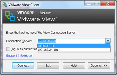
In order to automate the process of selecting either the VMware Horizon View connection server across the WAN or the user-assigned virtual desktop that is locally running in Cisco UCS E-Series, the VMware Horizon View client software can be modified to present the alternative authentication server addresses. The following screen shots show an example of how to configure VMware Horizon View client software registry in a Windows 7 thick client or Windows embedded thin client in order to list the VMware Horizon View connection server address and the locally assigned VMware Horizon View hosted virtual desktop address.
1. Open “regedit” using the Windows start menu

If in your environment you have VMware soft Horizon View [[CORRECT?]] clients installed either on full-blown Windows or on a thin client with Windows embedded, you may use the registry key BrokerHistory to add multiple existing connection brokers.
2. You can create the key under [HKEY_CURRENT_USER\Software\VMware, Inc.\VMware VDM\Client]. However, because this is a USER registry key you will need to merge the registry changes during logon time trough scripts or GPO

3. After you creat this key the VMware Horizon View client automatically lists the available servers for login.
Atlantis ILIO Deployment Option
For high-density virtual desktop deployments or expert-user workload profiles (with high I/O operations per second [IOPS] workloads), we recommend that you install Atlantis ILIO technology on the Cisco UCS E-Series server to boost IOPS performance using SAS 10K-rpm hard drives. Atlantis ILIO has the following benefits. You can:
● Deploy up to 35 high-performance virtual desktops on a single Cisco E-Series server module.
● Lower the cost per virtual desktop using Atlantis ILIO with SAS disks.
● Deliver a better-than-PC user experience.
For more Atlantis ILIO information, see: http://www.atlantiscomputing.com/products/.
Installing Cisco Office-in-a-Box
First, an administrator must install VMware ESXi on the Cisco UCS E-Series service module. The Cisco UCS E-Series management tool, the Cisco Integrated Management Controller, has multiple options on how to install an operating system on the server. This procedure explains how to mount an ESXi image on the available SD card using the “host image mapping” capability on the Cisco UCS E-Series server and how to start the installation of ESXi off the mounted image. An FTP or HTTP server is required to host the ESXi installation files in bootable ISO format.
1. Log in to the Cisco Integrated Management Controller.

The default username is admin and the password is password.
2. In the Server tab, click Host Image Mapping.

The Host Image Mapping screen opens.

3. In the URL field, enter the full image name including the extension. Click Download. When the download is complete, click Map Image to Host.

4. In the Server tab, click BIOS and update the boot order so that CDROM is the highest priority. (Host image map acts as a virtual CDROM when it is mounted.)

5. Launch the KVM console for the server and reload server. From the Server tab, click Summary > Launch KVM Console > Power Cycle Server.
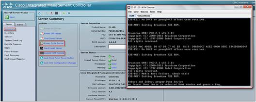
The server boots from the VMware ESXi bootable image.
6. Follow the VMware ESXi installation wizard.

7. After the ESXi installation is complete, unmap the ESXi boot image from the server to prevent a new fresh installation. Click Unmap Image. (Deleting the image is optional.)

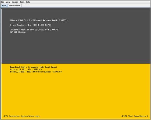
The VMware ESXi installation is complete.
8. Reload the router and configure VMware ESXi for network access.
To install VMware Horizon View using the fully distributed model, VMware offers the VMware Rapid Desktop Appliance solution that enables quick and easy provisioning of the entire VDI solution on a partner-certified solution. The Cisco UCS E-Series server has been validated by VMware and is available using VMware Horizon View 5.1 or 5.2. The Cisco UCS E-Series node requires VMware vSphere/ESXi 5.0 or later.

For information on the VMware Rapid Desktop Appliance solution, see:
http://www.vmware.com/solutions/desktop/rapid-desktop.html.
To install a VMware Horizon View solution with central management and distributed VDI sessions, VMware Horizon View 5.2 must be installed at the headquarters or data center site. For installation guide and system requirements, see: http://pubs.vmware.com/view-52/topic/com.vmware.ICbase/PDF/horizon-view-52-installation.pdf.
The Cisco UCS E-Series server requires VMware vSphere/ESXi 5.1, and the server must be added as a host to the data center VMware vCenter. We recommend that each Cisco UCS E-Series server be staged at headquarters with the appropriate VMware ESXi installation and desktop primary image (virtual machine template) that will be used for VDI pool creation. Staging the Cisco UCS E-Series server prevents the need for transferring large files across the WAN. After the Cisco UCS E-Series server is installed and running at the remote office with connectivity back to the data center, the administrator adds the Cisco UCS E-Series VMware ESXi host to vCenter so that the Cisco UCS E-Series server can participate as a resource platform for desktop pool creation. Using the VMware Horizon View management application, an administrator creates a desktop pool by selecting the desktop primary image hosted on the Cisco UCS E-Series server as the template for the pool. Then the administrator selects the Cisco UCS E-Series computing resource as the hosting node for the pool. The pool can be created as full clones of the primary image or as linked clones. In VMware Horizon View, full clone pools deliver persistent desktop pools where each individual desktop virtual machine is dedicated to an entitled user. Linked-clone pools deliver nonpersistent desktop pools where a group of users are entitled to the pool of linked-clones desktops and are connected to any desktop that is available in the pool. With linked clones, no user data or personalization of the desktop is saved after a user logs out of the VDI session.
To create a VDI pool using VMware Horizon View, follow these steps:
Notes: This example shows linked clones. If you plan to test with Atlantis ILIO, first install Atlantis ILIO on your Cisco UCS E-Series server. See “Atlantis ILIO Installation and Configuration.”
1. Log in to the VMware Horizon View management console, and click Pools and Add.
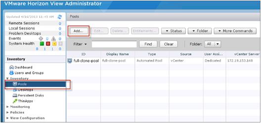
2. Click Type, select Automated Pool, and click Next.

3. Click User Assignment, select Dedicated and Enable automatic assignment, and click Next.

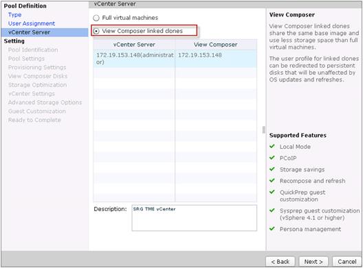
4. Click vCenter Server and select View Composer linked clones.
5. Click Pool Identification. Name your VDI pool, and click Next.

6. Click Pool Settings. Keep the pool settings defaults and click Next. For information about pool settings and how to manage them, see the VMware Horizon View Administration Guide

7. Click Provisioning Settings. Enter a naming pattern for the new VDI virtual machines and the number of virtual machines to create.

8. Click View Composer Disks. Keep the default values, and click Next.

9. Click Next through Storage Optimization.
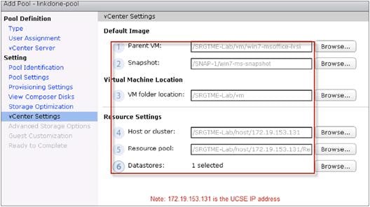
10. Click vCenter Settings. Select the parent virtual machine (the virtual machine template) and snapshot. For the resource pool, select the Cisco UCS E-Series server. For storage, select the Cisco UCS E-Series DAS.
11. Click Advanced Storage Options. Keep the default values, and click Next.

12. The AD domain should be automatically selected, so leave AD container set to the default.
You can use VMware QuickPrep or Microsoft Sysprep to tailor each created virtual machine for use (computer name, domain registration). This example uses Sysprep using a prepared vCenter Windows customization template. See the vSphere Virtual Machine Administration guide to learn more about customization templates.

13. Click Next.
14. Verify settings, and click Finish. The virtual machine pool is now created.
Atlantis ILIO Installation and Configuration
A preconfigured Atlantis ILIO installation for deployment on the Cisco UCS E-Series server is being developed and will be available soon.
To install and configure Atlantis ILIO, follow these steps:
1. Import the Atlantis ILIO Persistent VDI v3.2 Open Virtualization Format (OVF).
2. Configure the Atlantis ILIO virtual machine with these configuration settings:
| Storage utilized for Atlantis ILIO appliance |
5 GB |
| Storage allocated by Atlantis ILIO for the desktops |
All available storage from local disks (3 x 900-GB SAS disk in RAID 5) |
| Memory allocated for the appliance |
10 GB |
| vCPUs allocated |
2 vCPUs, with reservation of 1 vCPU |
3. Power on the Atlantis ILIO virtual machine and log in on the console
(username: poweruser, password: poweruser).
4. Use the in-console setup wizard to set up networking, host name, time zone, etc.
a. Use DHCP or static for the first interface.
b. Enter the host name for this virtual machine.
c. Enter the correct time zone.
d. Configure keymap. (Select Don’t touch keymap unless you know what you are doing.)
e. Before you click Next, press Ctrl-C. The advanced configuration file for Atlantis ILIO opens. Use the editor to change VMDATA_CACHE_ON: True to VMDATA_CACHE_ON: False. Press Ctrl-X to save the file to /etc/ilio/config.yml. Select yes to overwrite.
f. Continue with the configuration wizard. Select Persistent as the deployment option, Local Disk as the Storage Type, and /dev/sdb as the data disk.
You might get a message that says that the resources might not be sufficient. Ignore the message and continue the setup.
5. Select NFS as the data store type to mount to ESXi.
6. Create a data store in vSphere on the Cisco UCS E-Series server using the IP address information from step 4a. The mount path is /exports/ILIO_VirtualDesktops.
7. Use your standard virtual desktop provisioning tools to provision virtual desktops in the Atlantis ILIO data store.
Atlantis ILIO Test Results
Iometer
Iometer is an I/O subsystem measurement and characterization tool for single and clustered systems. Iometer was developed by the Intel Corporation and announced at the Intel Developers Forum (IDF) on February 17, 1998. Since then it has been widely adopted within the industry.
Meanwhile, Intel has discontinued work on Iometer, and it was given to the Open Source Development Lab (OSDL). In November 2001, a project was registered at SourceForge.net, and an initial drop was provided. In February 2003, the project was relaunched and is driven by an international group of individuals who are continuously improving, porting, and extending the product. Table 3 lists Iometer test specifications, and Figure 6 shows an Iometer test on Atlantis ILIO.
Table 3. Iometer Specifications Used for Testing
| Iometer VDI Workload |
|
| Transfer size |
4 K |
| Write-read ratio |
80:20 |
| Random-sequential ratio |
80:20 |
| Size of the test disk |
10 GB |
| Number of outstanding IOs |
64 |

Login VSI
Overall desktop performance was determined by using Login VSI 3.6 with the medium no-flash workload to measure response times. The Login VSI medium workload includes Word, Outlook, Excel, PowerPoint, Internet Explorer, BullZip PDF Printer, and 7-Zip. When you use the Login VSI Pro product, you can choose to test VDI deployments with a various preconfigured workloads or a custom workload.
Atlantis Computing considers Login VSI medium to be a lighter workload with fewer IOPS per desktop than a typical production VDI environment. Therefore, Atlantis Computing recommends that you create a custom workload that closely emulates the production VDI environment with the actual image that will be used in the VDI deployment.
Summary of the Login VSI medium workload:
● Use Outlook to browse 10 messages.
● Use Internet Explorer and leave one instance open (BBC.co.uk), and browse to one instance.
● Browse to Wired.com and Lonelyplanet.com.
● Use one instance of Word to measure response time and one instance to review and edit a document.
● Use BullZip PDF Printer and Acrobat Reader to print the Word document to PDF.
● Use Excel to open a very large randomized sheet.
● Use PowerPoint to review and edit a presentation.
● Use the command-line version of 7-Zip to compress the output of the session.
For more information, visit: http://www.LoginVSI.com/workloads.
Login VSI Test Configuration
In this test, Login VSI 3.6 Dynamic with a 30-second logon interval was used to establish the maximum density. Login VSI Dynamic works by taking a baseline of the first 15 Login VSI sessions (1858 milliseconds in our test). Then it uses a calculation to determine when the dynamic response time threshold is reached, which represents the maximum density that the server can support with acceptable user experience. (In this test, VSImax was not reached, which indicates that the system was not yet CPU or storage starved.)
At the point where the response time hits 4000 ms, Login VSI determines that you have reached the Login VSImax, or the maximum number of desktops that can be supported by on that particular server.
Test Parameter Configuration
The Microsoft Windows Base Template that is used for the testing has these characteristics:
| OS |
Windows 7 |
| Format of the virtual machine |
VMware ESX-based virtual machine |
| Virtual hard disk size |
70 GB thick provisioned, used space 33.59 GB |
| RAM used |
1024 MB |
| CPUs |
1 vCPU |
The Atlantis ILIO Virtual Appliance uses these host resources:
| Storage utilized for Atlantis ILIO appliance |
5 GB |
| Storage allocated by Atlantis ILIO for the desktops |
60 GB (accommodates 35 Windows 7 VMs) |
| Memory allocated for the appliance |
10 GB |
| CPU allocated |
2 vCPU (1.999 GHz) |
Test Results
The blue line in Figure 7 shows the average response time across all of the virtual desktops. The tested configuration supported 35 virtual desktops without reaching the VSImax score. The response time performance was well under the threshold of 4000 ms, with an average of less than 2000 ms for the entire test run. Therefore, the maximum density for the tested architecture is more than 35 desktops when more memory is available.
The user experience stayed very consistent, even when the session density increased.

Additionally, boot-time testing of a single virtual desktop showed a consistent boot time from shutdown to login prompt between 15 and 20 seconds, which is faster than that of most physical PCs.
Conclusion
The Cisco Office-in-a-Box solution with VMware Horizon View delivers a branch-office desktop solution that saves OpEx, TCO, and space and delivers an excellent user experience. By converging all IT services in a single box, the small office or retail store also saves on energy consumption and becomes simpler to manage.
For More Information
Read more about Cisco Office-in-a-Box and the Cisco UCS E-Series server at http://www.cisco.com/go/ucse, or contact your local representative.
 Feedback