Deploying 90W Cisco UPOE+ with Cisco Catalyst 9000 Switches Deployment Guide
Available Languages
Bias-Free Language
The documentation set for this product strives to use bias-free language. For the purposes of this documentation set, bias-free is defined as language that does not imply discrimination based on age, disability, gender, racial identity, ethnic identity, sexual orientation, socioeconomic status, and intersectionality. Exceptions may be present in the documentation due to language that is hardcoded in the user interfaces of the product software, language used based on RFP documentation, or language that is used by a referenced third-party product. Learn more about how Cisco is using Inclusive Language.
This document provides detailed guidelines for deploying the Cisco® Smart Building Solution with the Cisco Catalyst® 9000 switching family and enterprise Internet of Things (IoT) endpoints that use Power over Ethernet (PoE), such as LED lighting fixtures, motorized blinds, cameras, and USB-C dongles. It includes information about the system's architecture, possible deployment models, and configuration required on the Cisco network nodes. It also recommends best practices and potential issues to be aware of when deploying the solution. Vendor-specific information and implementation details are not covered here. Please refer to the vendor-specific documentation and recommendations that are specific to a particular endpoint. The deployment models and configuration recommendations provided in this document are applicable to different types of PoE-powered enterprise IoT endpoints.
The detailed implementation of the Cisco campus network architecture is beyond the scope of this document. For more details on the campus network architecture, refer to the Design Zone for Campus Wired and Wireless LAN.
Audience
This document is intended for system architects; network, computer, and IT design engineers; systems engineers; field consultants; and customers who want to understand how to deploy an indoor IoT infrastructure. It is written with the assumption that the reader is familiar with the basic concepts of IP protocols, switching, routing, and security.
The Cisco Smart Building Solution helps different building systems converge on a single IP network. When the lighting and other building systems are connected via Cisco Catalyst 9000 switches, they can be monitored and managed together by the enterprise Cisco DNA Center. The Catalyst 9000 switches installed in the wiring closet can power endpoints in spaces such as audio privacy rooms, conference rooms, team rooms, sections of a floor, etc. The switches are available in multiple form factors and port densities to address different design models. They are capable of providing PoE up to 90W on each port based on the IEEE 802.3bt standards. The specific Catalyst 9000 switch models that support PoE up to 90W are covered later in “What is Cisco UPOE+?”
Two deployment models are typically used: a distributed deployment model and a centralized deployment model. In the centralized model, the IoT endpoints connect directly to the access switches residing in the wiring closet. In the distributed model, the IoT endpoints such as lights connect directly to the Cisco Catalyst Digital Building Series Switches deployed in the ceiling space. In the distributed model, the Digital Building Series switches further connect to enterprise access switches in the wiring closet. This document focuses on the centralized deployment model, in which the IoT endpoints are connected directly to the Catalyst 9000 switches.
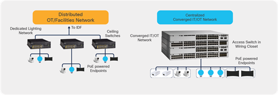
Comparison of the distributed and centralized deployment models
2. What is Cisco UPOE+?
Cisco UPOE+ combines the latest IEEE 802.3bt PoE standard with support for all previous IEEE standards and Cisco UPOE®. With the advent of 90W delivered by Cisco UPOE+, smart building transformation has accelerated by incorporating several measures to safely, efficiently, and cost-effectively deliver power and data using a common network structure. For detailed information on 90W Cisco UPOE+ and IEEE 802.3bt, please refer to the IT and OT convergence white paper.
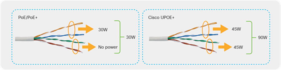
Cisco UPOE+ uses the same cabling standard as PoE. However, instead of delivering power over two of the twisted pairs, it provides the capability to source up to 90W of power by using all four twisted pairs of standard Ethernet cabling (Category 5e or better). It does this by using two Power Sourcing Equipment (PSE) controllers to power both the signal pairs and the spare pairs. Cisco UPOE+ assures a minimum of 71W of power to the Powered Device (PD). Cisco recommends the use of a 22-gauge cable to efficiently carry the power.
Complete details on the 802.3bt standards can be found in the IEEE 802.3bt-2018 document.
Architectural differences between PoE/PoE+ and Cisco UPOE+
Table 1 summarizes the differences between PoE, PoE+, Cisco UPOE and UPOE+.
Table 1. PoE, PoE+, Cisco UPOE, and UPOE+ comparison
|
|
PoE |
PoE+ |
Cisco UPOE |
Cisco UPOE+ |
| Minimum cable type |
Category 5e |
Category 5e |
Category 5e |
Category 5e |
| IEEE standard definition |
802.3af |
802.3at |
Cisco proprietary |
802.3bt |
| Maximum power per PSE port |
15.4W |
30W |
60W |
90W |
| Maximum power per PSE port |
15.4W |
30W |
60W |
90W |
| Maximum power to PD |
12.95W |
25.5W |
51W |
71.3W |
| Twisted pairs used |
2 pairs |
2 pairs |
4 pairs |
4 pairs |
| Distance |
Under 100 m |
|||
| Performance |
No impact on network performance of 10/100/1000 Mbps links to the PD |
|||
For 802.3bt Type 4 installations specific to lighting and applications that are concerned with maximum power transmission efficiency and low data speed installs (i.e., 1gbps or less), Cisco recommends 22AWG conductors in the cable with a minimum of Cat 5e cable. For IEEE 802.3bt Type 4 installations requiring higher data speeds, it is recommended to use Cat 6a with 23AWG or larger conductors
Other options that comply with the National Electric Code (NEC):
• Cables with 24AWG conductors rated at 60 ℃, in bundle sizes of 37 or less
• Cables with 23AWG conductors rated at 60 ℃, in bundle sizes of 61 or less
• Cables with 24AWG conductors rated at 75 ℃, in bundle sizes of 91 or less
• Cables with 23AWG conductors rated at 75 ℃, in bundle sizes of 192 or less
Catalyst 9000 switches are purpose-built for enterprise networks. The switches come in both fixed and modular form factors to meet different port densities and address different deployment models. Within the Catalyst 9000 family of switches, the following series support PoE capabilities.
Within the above list of switches, the Catalyst 9300 and 9400 Series support Cisco UPOE+, providing power up to 90W.
2.1. 90W Cisco UPOE+ use cases
Traditionally, IT and OT had different and specific roles in the system network, but lately they have been in synergy and are increasingly merging. Additionally, numerous endpoints are now entering the network, such as USB-C dongles, digital signage, motorized shades, intelligent sensors, touch-screen PCs, badging systems, emergency alert systems, and high-definition security cameras, and the list is ever growing.
Daisy-chaining the PoE lights greatly reduces cost by using fewer ports, since more lights can be connected on a single switch port. Connecting PoE pass-through desktop switches really simplifies overall cabling and is ideal for space-constrained areas. PoE-powered USB-C dongles for charging laptops as well as providing data connectivity on the same cable have the potential to replace the existing power bricks. Finally, the PoE-powered IoT ecosystem is also seeing an addition of new high-power endpoints such as desktop monitors, UHD cameras, minibars, HVAC, etc. creating great use cases for 90W UPOE+. Cisco’s integration of 90W UPOE+ line cards in its Catalyst 9400 Series modular switches as well as Catalyst 9300 Series fixed switches is making all of the use cases above a reality.
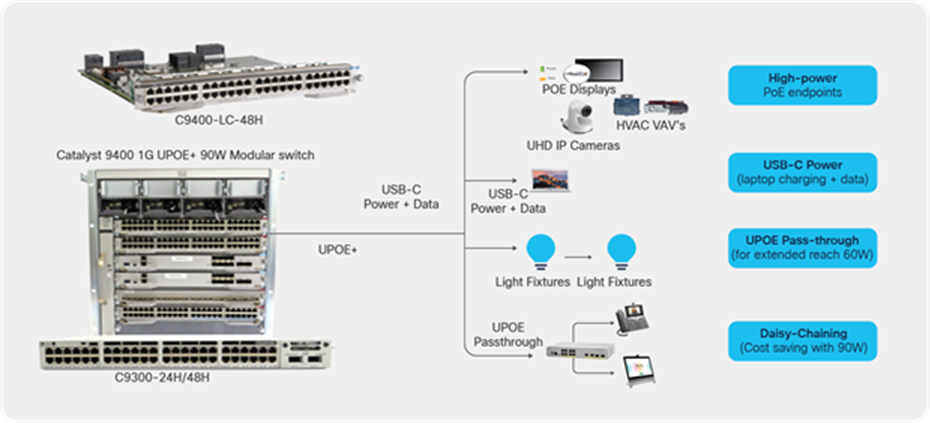
The 90W UPOE+ standard is driving new use cases
This section provides an overview of the Smart Building Solution deployment using 90W-capable switches in a centralized deployment model.
Different network topologies can be designed based on your requirements. In this deployment we will cover the initial installation followed by a description of how it can be deployed in a campus network architecture.
Figure 4 shows an example of the network topology. It uses the centralized deployment model, in which the switches are in a wiring closet. At the access layer, Catalyst 9300 or 9400 Series switches can be used to support PoE up to 90W. Catalyst 9300 Series switches can be deployed standalone or in StackWise®-480 mode, depending on the port density and requirements. The deployment model can be a 3-tier architecture with access, distribution, and core layer, or a 2-tier architecture with access and distribution/core layers. In the distribution/core layer, the Catalyst 9400, 9500, or 9600 Series can be used to provide IP connectivity to the IoT endpoints. These switches can be deployed in either standalone or StackWise virtual mode, depending on the requirements.
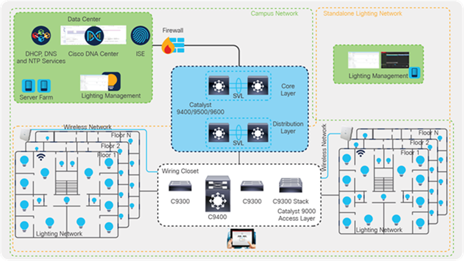
Network topology
In this deployment guide, Catalyst 9300 Series switches have been used at the access layer in standalone and StackWise-480 mode. At the distribution/core layer, Catalyst 9500 Series switches are used. Specific models are outlined in Table 2 of this document. Shared services such as Dynamic Host Configuration Protocol (DHCP)/DNS, Cisco DNA Center, and Identity Services Engine (ISE) are located in the data center. Additionally, the lighting management software is within the data center.
The components of the topology are a mix of Cisco products and IoT endpoints such as third-party LED lighting endpoints, Cisco and third-party cameras, Cisco IP phones, and PoE-capable USB-C dongles that can power and provide data connectivity to laptops and PCs. The tables below list these components.
Table 2. Cisco components
| Cisco product |
Software release |
Description |
Role |
| Catalyst 9300 Series switches |
17.3.1 |
The 9300 Series switches are used in the access layer. The C9300-24H is the specific model used in this topology. |
Access layer |
| Catalyst 9500 Series switches |
17.3.1 |
The 9500 Series switches are configured in StackWise Virtual mode and are used in the core layer. C9500-24Q is the specific model used in this topology. |
Distribution/core layer |
| Cisco DNA Center |
2.1.2.3 |
Cisco DNA Center is the network management and command center used for automation, assurance, and policy control. |
Management |
| Cisco Identity Services Engine (ISE) |
2.7 P2 |
Cisco ISE streamlines security policy management. It enables control of access across wired, wireless, and VPN connections. |
Security |
Table 3. Third-party components
| Third-party product |
Purpose |
Description |
| DNS server |
Provides IP addresses and DNS service to all endpoints. |
Microsoft Windows Server (2016) |
| DHCP server |
Provides dynamic IP addresses to the endpoints. |
Catalyst 9000 switch/Microsoft Windows Server (2016) |
| 90W PoE LED lights |
Lighting endpoints. |
90W LED lights |
| Virtualization software for Cisco UCS® |
Used to host management software (VMs) to discover and manage lighting fixtures. |
Lighting management software |
| USB-C dongles |
Used for data and power management of laptops. |
90W USB-C dongles (USB-C to Ethernet) |
| Laptops |
Endpoints connected to PoE-powered USB-C dongles. |
Laptops with USB-C ports |
| Management and control software |
Discovers and controls lighting infrastructure. |
Lighting discovery and management software |
The network-powered IoT endpoints should be deployed on a separate logical network (VLAN) based on the endpoint type and requirements. For example, a lighting network should be deployed in its own dedicated network, as the light fixtures would need to talk only to their controller. When you have multiple third-party PoE lights, we recommended separating them into different VLANs to make sure that the control software from each vendor does not interfere with the other lighting endpoints.
The table below summarizes the logical networks (VLANs) that are configured to segregate the traffic on the access switches.
Table 4. VLAN segmentation
| VLAN |
Purpose |
Network/mask |
| 10 |
VLAN for light fixtures for vendor 1 |
172.16.10.0/24 |
| 20 |
VLAN for cameras |
172.16.20.0/24 |
| 30 |
VLAN for light fixtures for vendor 2 |
172.16.30.0/24 |
| 40 |
Data VLAN |
172.16.40.0/24 |
| 100 |
Management VLAN |
192.168.100.0/24 |
Note: The VLANs shown above are the ones used in this deployment guide. VLAN numbering and subnets will be based on your requirements.
Cisco Catalyst 9000 switches support various industry-standard open programmable protocols such as NETCONF, RESTCONF, Google gNMI, etc. to be used to interface with external automation software toolchains. Cisco Catalyst 9000 supports the IETF-based YANG data modeling language to automate network configuration and to monitor network and system functions. The APIs support Remote Procedure Calls (RPCs) for communication using various industry-standard encoding formats, including XML, JSON, and Google gRPC.
To gather PoE statistics using APIs, the following YANG model is supported on the Catalyst 9000 switches:
Cisco-IOS-XE-poe-oper.yang
More information on the YANG model can be found at poe-oper Model. A complete list of supported YANG models for Cisco IOS® XE is located at Github.
The ecosystem of 90W IoT endpoints is continually expanding. We continue to see the evolution of PoE-powered USB-C dongles that can charge laptops and provide data connectivity at the same time. Similarly, lighting infrastructure is leveraging higher PoE power to daisy-chain multiple lights via a single switch port. For this deployment guide, we have used PoE-powered USB-C dongles and lighting endpoints that are 802.3bt compliant. In this section, we take a brief look at the specifications and characteristics of the PoE-powered IoT endpoints.
Power consumption of the switch and heat dissipation numbers can be derived using the Cisco Power Calculator.
USB-C dongle for PoE and data connectivity
A PoE-powered USB-C dongle provides PoE and data connectivity to a laptop over a single Ethernet connection. The endpoint (laptop in this case) is transparent to these changes, while the switch port provides required PoE and network connectivity.
There is no difference in how you configure the access port when using a USB-C dongle, other than enabling additional PoE capabilities such as Perpetual and Fast PoE. The configuration for the switch port looks like the one shown below.
| interface GigabitEthernet3/0/11 description Data-VLAN switchport access vlan 40 switchport mode access spanning-tree portfast power inline port perpetual-poe-ha power inline port poe-ha device-tracking attach-policy IPDT_POLICY end |
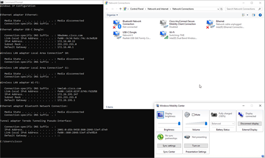
Once the laptop is connected to the switch port, it starts to draw power to charge while getting data connectivity at the same time. The following is a snapshot of a Lenovo laptop that is connected to the Catalyst 9300 Series switch port via a USB-C dongle.
| *Dec 22 17:43:06.775: %ILPOWER-5-DETECT: Interface Gi3/0/11: Power Device detected: IEEE PD *Dec 22 17:43:07.756: %ILPOWER-5-POWER_GRANTED: Interface Gi3/0/11: Power granted *Dec 22 17:43:07.756: %ILPOWER-5-PWRGOOD_SPARE_PAIR: Interface Gi3/0/11: spare pair power good *Dec 22 17:43:11.995: %LINK-3-UPDOWN: Interface GigabitEthernet3/0/11, changed state to up *Dec 22 17:43:12.995: %LINEPROTO-5-UPDOWN: Line protocol on Interface GigabitEthernet3/0/11, changed state to up |
The snapshot below shows the power negotiation between the PD (USB-C dongle) and PSE (Catalyst 9300 Series switch).
| C9300-Stack#sh power inline gigabitEthernet 3/0/11 detail Interface: Gi3/0/11 Inline Power Mode: auto Operational status (Alt-A,B): on,on Device Detected: yes Device Type: Ieee PD Connection Check: SS IEEE Class (Alt-A,B): 8 Physical Assigned Class (Alt-A,B): 8 Discovery mechanism used/configured: Ieee and Cisco Police: off
Power Allocated Admin Value: 90.0 Power drawn from the source: 90.0 Power available to the device: 90.0 Allocated Power (Alt-A,B): 90.0
Actual consumption Measured at the port(watts) (Alt-A,B): 60.4 Maximum Power drawn by the device since powered on: 66.5
Absent Counter: 0 Over Current Counter: 0 Short Current Counter: 0 Invalid Signature Counter: 0 Power Denied Counter: 0
Power Negotiation Used: None LLDP Power Negotiation --Sent to PD-- --Rcvd from PD-- Power Type: - - Power Source: - - Power Priority: - - Requested Power(W): - - Allocated Power(W): - -
Four-Pair PoE Supported: Yes Spare Pair Power Enabled: Yes Four-Pair PD Architecture: Shared |
USB-C dongle providing power and network connectivity
90W lighting fixtures
Multiple vendors have developed network gateways that can daisy-chain multiple light fixtures that connect to a single port of an access switch to leverage the 90W that is available on the port. This helps build a scalable lighting network within a campus network. In this section, we will go through the configuration that is needed on the Catalyst 9300 Series switch for initial installation of the lighting network.
Light fixture installation
The lighting vendor will provide a recommendation for installation and cabling between the light and the Cisco switch. For 802.3bt Type 4 installations specific to lighting and applications that are concerned with maximum power transmission efficiency and low data speed installs (i.e., 1gbps or less), Cisco recommends 22AWG conductors in the cable with a minimum of Cat 5e cable. For installs that need higher Ethernet speeds, either today or in the future, Cat6A cable is recommended.
Initial installation of the Cisco Catalyst 9300 Series switch
The switch by default comes with a preloaded image that can be accessed via the console cable. The switch can be upgraded to the required image by following the software upgrade guide.
Configuring the Cisco Catalyst 9300 Series UPOE+ switch for initial installation
This section covers the basic configuration and network topology needed for the initial installation of the light fixtures.
Smart Building Solution initial setup in the wiring closet with Cisco Catalyst 9300 Series switches
The configuration below is required on the switch so that LED lights can be assigned an IP address and be discovered by the respective third-party control software.
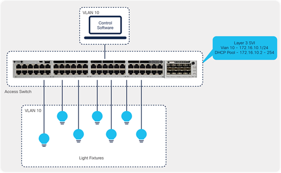
● Define a VLAN that can be used for the lighting network.
| vlan 10 name Lighting-VLAN |
● Enable Link Layer Discovery Protocol (LLDP) on the switch.
| lldp run |
Light fixtures have to communicate with the controller to perform automated and sensor operations and firmware upgrades. This communication occurs over IP on the Ethernet network; hence each light fixture should be assigned an IP address. To assign the IP address dynamically, the Catalyst 9300 Series switch can act as a DHCP server.
● Configure a DHCP server on the Catalyst 9300 Series switch.
| ip dhcp pool LED_LIGHTS network 172.16.10.0 255.255.255.0 default-router 172.16.10.1 ip dhcp excluded-address 172.100.100.1 |
In scenarios where the requirement is to maintain the same IP address for an endpoint connected to a switch port, port-based address allocation can be used on Catalyst 9000 switches so that the same IP address is assigned to the endpoint connected to the interface, regardless of interface bounce or endpoint replacement.
| ip dhcp pool LED_LIGHTS network 172.16.10.0 255.255.255.0 default-router 172.16.10.1 ip dhcp excluded-address 172.100.100.1 ip dhcp server use subscriber-id client-id |
DHCP uses the subscriber ID configured on the interface to generate the client ID. If no subscriber ID is configured, the client ID is automatically generated based on the short name of the interface. The client ID already present in the message is ignored.
Once the light fixtures get an IP address, they can be discovered by the control software. Additional settings and firmware upgrades should be possible from the respective third-party control software.
As soon as the lighting endpoint is connected to the switch port, the power is granted to the PD based on the requested class.
| *Dec 22 11:21:45: %LINK-3-UPDOWN: Interface GigabitEthernet1/0/14, changed state to down *Dec 22 11:21:46: %SYS-5-CONFIG_I: Configured from console by console *Dec 22 11:21:48: %ILPOWER-5-DETECT: Interface Gi1/0/14: Power Device detected: IEEE PD *Dec 22 11:21:50: %ILPOWER-5-POWER_GRANTED: Interface Gi1/0/14: Power granted *Dec 22 11:21:50: %ILPOWER-5-PWRGOOD_SPARE_PAIR: Interface Gi1/0/14: spare pair power good *Dec 22 11:21:53: %LINK-3-UPDOWN: Interface GigabitEthernet1/0/14, changed state to up |
In this case, we have more than one light in a daisy chain that is connected to port G1/0/14. We can see below that the PD has requested Class 8.
| C9300#sh power inline gigabitEthernet 1/0/14 detail Interface: Gi1/0/14 Inline Power Mode: auto Operational status (Alt-A,B): on,on Device Detected: yes Device Type: Ieee PD Connection Check: SS IEEE Class (Alt-A,B): 8 Physical Assigned Class (Alt-A,B): 8 Discovery mechanism used/configured: Ieee and Cisco Police: off
Power Allocated Admin Value: 90.0 Power drawn from the source: 90.0 Power available to the device: 90.0 Allocated Power (Alt-A,B): 90.0
Actual consumption Measured at the port(watts) (Alt-A,B): 83.5 Maximum Power drawn by the device since powered on: 83.5
Absent Counter: 0 Over Current Counter: 0 Short Current Counter: 0 Invalid Signature Counter: 0 Power Denied Counter: 0
Power Negotiation Used: IEEE 802.3bt LLDP LLDP Power Negotiation --Sent to PD-- --Rcvd from PD-- Power Type: Type 2 PSE Type 2 PD Power Source: Primary PSE Power Priority: low critical PD 4PID: 0 0 Requested Power(W): 71.3 71.3 Allocated Power(W): 71.3 71.3 Requested Power ModeA(W): 0.0 0.0 Allocated Power ModeA(W): 0.0 0.0 Requested Power ModeB(W): 0.0 0.0 Allocated Power ModeB(W): 0.0 0.0 PSE Powering Status: 4 pair SS PD Ignore PD Powering Status: Ignore SS PD PSE Power Pair ext: Both Alternatives Ignore DS Class Mode A ext: SS PD Ignore DS Class Mode B ext: SS PD Ignore SS Class ext: Class 8 Class 8 PSE Type ext: Type 4 PSE Ignore PSE Max Avail Power: 71.3 0.0 PSE Auto Class Supp: No No PD Auto Class Req: No No PD Power Down Req: No No PD Power Down Time(sec): 0 0
Four-Pair PoE Supported: Yes Spare Pair Power Enabled: Yes Four-Pair PD Architecture: Shared |
| C9300-Stack#sh power inline upoe-plus gigabitEthernet 3/0/11
Device IEEE Mode - BT
Codes: DS - Dual Signature device, SS - Single Signature device SP - Single Pairset device
Interface Admin Type Oper-State Power(Watts) Class Device Name State Alt-A,B Allocated Utilized Alt-A,B ----------- ------ ---- ------------- --------- --------- ------- ----------- Gi3/0/11 auto SS on,on 90.0 64.8 8 Ieee PD |
5. 90W Deployment in a campus network architecture
In an earlier section, we looked at how 90W endpoints such as light fixtures and USB-C dongles can be configured for initial installation and verification.
Once the endpoints are verified and validated, they can be migrated to an existing campus infrastructure. This section provides more details on how to design the endpoints’ subnet, controller software, and centralized DHCP/DNS server.
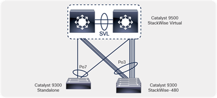
The access switches in the wiring closet (Cisco Catalyst 9300 Series standalone and stack) connect to a production network distribution/core switch with separate logical networks for light fixtures.

Cisco campus network architecture with Catalyst 9000 switches
In this topology, we have used Catalyst 9300 Series switches (C9300-24H/48H) in the access layers, both in standalone and StackWise-480 mode.
Catalyst 9500 Series switches (9500-24Q) are configured for StackWise Virtual mode and are acting as the distribution/core layer for this deployment guide.
Shared services such as Cisco DNA Center, ISE, and third-party lighting management software are connected to the data center switch in its own specific subnet.
5.2. Configuring DNS/DHCP services
This section covers dynamic IP addressing for 90W IoT endpoints such as light fixtures.
During the preliminary tests, the DHCP server for light fixtures is configured on a Catalyst 9300 Series switch. When this environment is migrated to a campus network architecture, DHCP addressing will also be migrated to a centralized DHCP server that manages multiple DHCP pools across the network.
In this deployment guide, the DHCP server is connected to the data center switch and is serving multiple IP pools across the campus network.
Table 5. IPv4 DHCP address pool configured on the Windows DHCP server
| DHCP pool |
Excluded IP |
Purpose |
| 172.16.10.0/24 |
172.16.10.1 |
DHCP pool for light fixtures from third-party vendor 1 |
| 172.16.20.0/24 |
172.16.20.1 |
DHCP pool for camera VLAN |
| 172.16.30.0/24 |
172.16.30.1 |
DHCP pool for light fixtures from third-party vendor 2 |
| 172.16.40.0/24 |
172.16.40.1 |
DHCP pool for data network |
| 192.168.100.0/24 |
192.168.100.1 |
DHCP pool for management network |
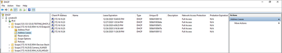
DHCP pools defined on the Windows server
Note: There may be multiple requirements from third-party vendors on how the IoT endpoints are discovered within the network. For example, a third-party lighting vendor may require a custom DHCP option so that lighting endpoints can communicate with the management software for discovery, management, and firmware upgrade operations. Necessary options have to be predefined in the DHCP pool for the discovery to work.
5.3. Campus network core/aggregation configuration
The UPOE+ access switches (Catalyst 9300 Series standalone and stack) are connected to the campus network distribution/core switches in a converged campus/large-scale deployment. A detailed description of the implementation of the campus network architecture is beyond the scope of this document.
In this guide, Catalyst 9500 Series switches are deployed in StackWise Virtual mode to provide campus network core, distribution, and Layer 3 routing functionalities for lighting and other 90W PoE endpoints that are connected across multiple access layer switches.
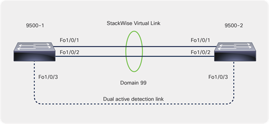
5.3.1. Cisco StackWise Virtual
Cisco StackWise Virtual is a network system virtualization technology that pairs two switches into one virtual switch. Switches in a Cisco StackWise Virtual solution simplify operational efficiency with a single control and management plane, scale system bandwidth with a distributed forwarding plane, and assist in building resilient networks using the recommended network design. Cisco StackWise Virtual allows two physical switches to operate as a single logical virtual switch.
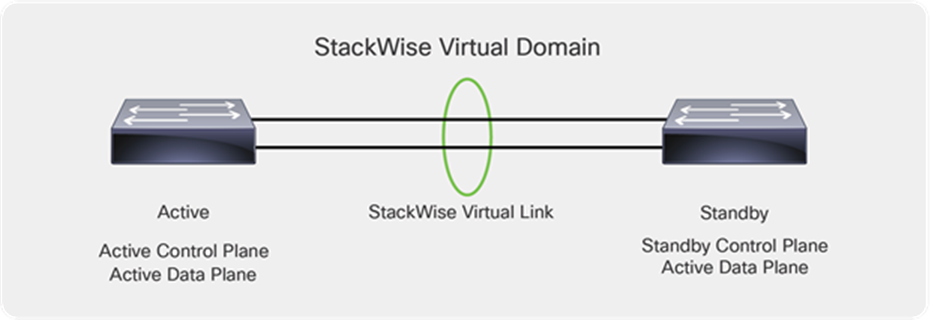
Catalyst 9500 Series switches deployed with StackWise Virtual
Within a StackWise Virtual domain, one device is designated as the StackWise Virtual active switch, and the other is designated as the StackWise Virtual standby switch (Figure 9). All control plane functions are centrally managed by the StackWise Virtual active switch, including:
● Management (Simple Network Management Protocol [SNMP], Telnet, Secure Shell [SSH] Protocol, etc.)
● Layer 2 protocols (Bridge Protocol Data Units [BPDUs], Protocol Data Units [PDUs], Link Aggregation Control Protocol [LACP], etc.)
● Layer 3 protocols (routing protocols, etc.)
● Software data path
Prerequisites for StackWise Virtual
● All the switches in the Cisco StackWise Virtual solution should be the same switch model.
● All the switches in the Cisco StackWise Virtual solution should be running the same license level.
● All the switches in the Cisco StackWise Virtual solution should be running compatible software versions.
Both of the Catalyst 9500 Series switches have been configured to operate as a StackWise Virtual pair.
The steps below outline the configuration that is required to convert two standalone 9500 Series switches to a StackWise Virtual pair.
Cisco StackWise Virtual configuration
● Configure the StackWise Virtual domain on 9500-1 and 9500-2.
| stackwise-virtual domain 99 |
● Configure the StackWise Virtual link.
| interface FortyGigabitEthernet1/0/1 stackwise-virtual link 1 interface FortyGigabitEthernet1/0/2 stackwise-virtual link 1 |
● Configure StackWise Virtual dual-active detection. This has to be configured on a different port than the StackWise Virtual link ports.
| interface FortyGigabitEthernet1/0/3 stackwise-virtual dual-active-detection |
● Save the configuration and reload the switch.
This step will convert the standalone switches to the StackWise Virtual domain once the switches come back online after the reload.
| C9500-Core-SVL#sh stackwise-virtual Stackwise Virtual Configuration: -------------------------------- Stackwise Virtual : Enabled Domain Number : 99
Switch Stackwise Virtual Link Ports ------ ---------------------- ------ 1 1 FortyGigabitEthernet1/0/1 FortyGigabitEthernet1/0/2 2 1 FortyGigabitEthernet2/0/1 FortyGigabitEthernet2/0/2 |
5.3.2. Configuring Layer 2 and Layer 3 services
This section defines the implementation of Layer 2 and Layer 3 logical interfaces on the Catalyst 9500 Series switch.
Below is the topology from the core/distribution layer to the access layer.
Distribution/core to access topology
● Configure VLANs, which must be created along with port assignments on the Catalyst 9500 Series switch.
| Vlan 10,20,30,40,100 |
The Catalyst 9500 Series switch in StackWise Virtual mode is acting as the gateway for the lighting VLAN and other 90W IoT endpoints in this deployment.
Configure a Layer 3 Switched Virtual Interface (SVI) for the 90W endpoints that are connected on the access switch. We recommend segmenting the VLANs based on the endpoint types. In this deployment guide, we have used VLAN 10 for the lighting network for vendor 1, VLAN 20 for the camera/surveillance network, VLAN 30 for the lighting network for vendor 2, VLAN 40 for data connectivity, and VLAN 100 for management connectivity across the site.
| interface Vlan10 ip address 172.16.10.1 255.255.255.0 ! interface Vlan20 description Camera ip address 172.16.20.1 255.255.255.0 ! interface Vlan30 ip address 172.16.30.1 255.255.255.0 ! interface Vlan40 description Data ip address 172.16.40.1 255.255.255.0 ! interface Vlan100 description Management ip address 192.168.100.1 255.255.255.0 |
Note: When migrating the lighting or any 90W IoT endpoints from a smoke test to a converged campus network, remove the SVIs of any VLANs that you may have created on wiring closet access switches. SVIs for these endpoints are configured at core/aggregation switches to provide Layer 3 services to the lighting network.
Create port-channel interfaces on the Catalyst 9500 Series switch to the wiring closet switches (Catalyst 9300 Series standalone and stack), as shown in the topology. Configure the links as trunks and allow the lighting VLANs, management VLAN, and other IoT endpoint VLANs on the trunk links.
Make sure the port channel has at least one interface from each physical switch of the StackWise Virtual pair.
● Below is the physical interface and port-channel configuration on the Catalyst 9500 Series switch to the 9300 Series standalone switch:
| interface FortyGigabitEthernet1/0/7 description Connection to C93-Standalone For 1/1/1 switchport trunk allowed vlan 10,11,20,30,40,100 switchport mode trunk channel-group 7 mode active ! interface FortyGigabitEthernet2/0/7 description Connection to C93-Standalone For 1/1/2 switchport trunk allowed vlan 10,11,20,30,40,100 switchport mode trunk channel-group 7 mode active ! interface Port-channel7 switchport trunk allowed vlan 10,11,20,30,40,100 switchport mode trunk end |
When connecting a Catalyst 9300 Series stack to the 9500 Series distribution/core, make sure that uplinks are distributed across active, standby, and member so that there is always redundancy during an active switch failover or when performing software upgrades using the Extended Fast Switch Upgrade feature.
Below, we have uplinks connected from all switches in the stack to the distribution/core. The number of uplinks has to be decided based on the bandwidth that would be needed from access to distribution/core.
● Below is the physical interface and port-channel configuration on the Catalyst 9500 Series switch to the 9300 Series stack switch:
| interface FortyGigabitEthernet1/0/8 description Connection to C93-Stack-SW1 For 1/1/1 switchport trunk allowed vlan 10,20,30,40,100 switchport mode trunk channel-group 3 mode active ! interface FortyGigabitEthernet1/0/9 description Connection to C93-Stack-SW2 For 2/1/1 switchport trunk allowed vlan 10,20,30,40,100 switchport mode trunk channel-group 3 mode active ! interface FortyGigabitEthernet1/0/10 description Connection to C93-Stack-SW3 For 3/1/1 switchport trunk allowed vlan 10,20,30,40,100 switchport mode trunk channel-group 3 mode active ! interface FortyGigabitEthernet1/0/11 description Connection to C93-Stack-SW4 For 4/1/1 switchport trunk allowed vlan 10,20,30,40,100 switchport mode trunk channel-group 3 mode active ! interface FortyGigabitEthernet2/0/8 description Connection to C93-Stack-SW1 For 1/1/2 switchport trunk allowed vlan 10,20,30,40,100 switchport mode trunk channel-group 3 mode active ! interface FortyGigabitEthernet2/0/9 description Connection to C93-Stack-SW2 For 2/1/2 switchport trunk allowed vlan 10,20,30,40,100 switchport mode trunk channel-group 3 mode active ! interface FortyGigabitEthernet2/0/10 description Connection to C93-Stack-SW3 For 3/1/2 switchport trunk allowed vlan 10,20,30,40,100 switchport mode trunk channel-group 3 mode active ! interface FortyGigabitEthernet2/0/11 description Connection to C93-Stack-SW4 For 4/1/2 switchport trunk allowed vlan 10,20,30,40,100 switchport mode trunk channel-group 3 mode active ! interface Port-channel3 switchport trunk allowed vlan 10,20,30,40,100 switchport mode trunk end |
5.3.3. DHCP relay agent
In a campus network architecture, IoT endpoints and the DHCP server are typically not located in the same subnet. A centralized DHCP server that resides in a shared environment serves multiple subnets on the access switches.
The gateway for these IoT endpoints resides on the Catalyst 9500 Series switches, which are operating in StackWise Virtual mode, as outlined in Figure 9. The gateways on the Catalyst 9500 Series have to relay these DHCP messages to the centralized DHCP server.
The configuration below shows how to enable a relay agent on the Catalyst 9500 Series switches:
| interface Vlan10 ip helper-address 172.16.99.53 ! interface Vlan20 ip helper-address 172.16.99.53 ! interface Vlan30 ip helper-address 172.16.99.53 ! interface Vlan40 ip helper-address 172.16.99.53 ! interface Vlan100 ip helper-address 172.16.99.53 |
Enable required routing on the 9500 Series switches to make sure the endpoint subnets have reachability to the shared services and lighting management subnets that reside in the data center network, as outlined in Figure 7.
In this deployment guide, we have used Open Shortest Path First (OSPF) as the interior gateway protocol to propagate local routes and learn remote routes from the data center switch.
| router ospf 10 log-adjacency-changes network 172.16.10.0 0.0.0.3 area 0 network 172.16.20.0 0.0.0.3 area 0 network 172.16.30.0 0.0.0.3 area 0 network 172.16.40.0 0.0.0.3 area 0 network 172.16.40.0 0.0.0.3 area 0 |
5.4. Campus network access configuration
This section covers the necessary configuration required on the access switches. Create different VLANs based on the types of endpoints located in the network.
● Define VLANs that can be used for the endpoint network.
| vlan 10 name Lighting-VLAN1 vlan 20 name Camera-VLAN vlan 30 name Lighting-VLAN2 vlan 40 name Data-VLAN vlan 100 name Management-VLAN |
● Enable LLDP on the switch.
| lldp run |
Autoconf or manual templates, as outlined in the “Autoconf to scale endpoint configurations” section, can be used to scale the configuration of the access ports on Catalyst 9300 Series standalone or stack switches. Below is the minimum configuration that is required on the switch port so that any 90W IoT endpoint that is connected to the downlink port can get an IP address from the DHCP server and be discovered by its controller.
| interface GigabitEthernet1/0/10 switchport access vlan < End Point Vlan > switchport mode access device-tracking attach-policy IPDT_POLICY power inline port perpetual-poe-ha power inline port poe-ha spanning-tree portfast |
The Cisco Catalyst 9000 switching platforms have many integrated security features that can provide threat defense capabilities for mitigating man-in-the-middle attacks and protecting the critical network infrastructure. This section details the switch configurations for basic Layer 2 security features that can be enabled to secure the network. These are optional features that can be enabled to secure the network.
Rogue DHCP servers can be detrimental to the security and usability of the network if not protected against properly. Rogue DHCP servers attack the network by assigning unrouteable IP addresses to clients, causing them to lose connectivity. They can also be used to issue malicious DNS servers. Users then looking to go to real websites will be sent to fake copies of these sites to steal credentials or information.
DHCP snooping is a tool used to combat rogue DHCP servers. It works by assigning one or more ports as trusted, meaning these ports lead to legitimate DHCP servers. The switch will then build a database of the untrusted hosts with leased IP addresses, MAC addresses, switch ports, and VLANs. Traffic being sent from these untrusted hosts will be filtered of any DHCP server messages, blocking any attempt to create a malicious DHCP server.
Perform the following steps on the Cisco Catalyst 9300 Series switch to configure IP DHCP snooping:
● Configure the required port as a DHCP snooping trusted port. This is usually the uplink port to the core.
| interface Port-channel7 ip dhcp snooping trust |
● Enable IP DHCP snooping globally and for the required VLANs
| ip dhcp snooping ip dhcp snooping information option ip dhcp snooping vlan 10-40 |
To prevent loops in Layer 2 networks, we use Spanning Tree Protocol (STP), but this can also hurt the network if it is not protected.
PortFast can be used on the switch ports where a single workstation or server is connected to allow the devices to connect to the network immediately, instead of waiting for the port to transition from the listening and learning states to the forwarding state. PortFast causes a switch port to enter the spanning tree forwarding state immediately, bypassing the listening and learning states.
In STP, a root bridge is elected. This decides which ports will be put in a forwarding or blocking state. If a device is added with a lower priority than the current root bridge, it will take over, causing a topology change and possibly blocking traffic from a wanted path. BPDU Guard is a protocol designed to solve this problem. When enabled, if a switch sees BDPU traffic coming from a port, it will automatically set it to the “errdisabled” state so that no traffic can pass.
We recommend enabling PortFast and BPDU Guard on the ports that are connected to lighting endpoints, as no BPDUs are expected on those ports.
● Enable PortFast and BPDU Guard using the command-Line Interface (CLI) as shown below:
| interface GigabitEthernet1/0/9 spanning-tree portfast spanning-tree bpduguard enable |
ARP cache poisoning is a malicious tool used to stage man-in-the middle attacks. It works by sending a forged Address Resolution Protocol (ARP) packet with the IP address of another device and the MAC address of itself to poison the host’s ARP cache. This means traffic destined for the legitimate device will instead be sent to the attacker. The attacker can then forward the traffic to its intended destination, making it look as if the traffic was never interrupted.
Dynamic ARP Inspection (DAI) is a tool that can be used to mitigate this threat. DAI uses the DHCP snooping database for IP-to-MAC address bindings. DAI then intercepts all ARP packets and drops any packet in which the IP-to-MAC address binding is not valid.
● Configure the uplink ports to be trusted:
| interface Port-channel7 ip arp inspection trust |
● Enable ARP Inspection per VLAN:
| ip arp inspection vlan 123 |
Storm control prevents traffic on a LAN from being disrupted by a broadcast, multicast, or unicast storm on one of the physical interfaces. A LAN storm occurs when packets flood the LAN, creating excessive traffic and degrading network performance. Errors in the protocol-stack implementation, mistakes in network configurations, or users issuing a denial-of-service attack can cause a storm.
With storm control, the port blocks traffic when the rising threshold is reached. The port remains blocked until the traffic rate drops below the falling threshold (if one is specified) and then resumes normal forwarding.
An action can be taken when a storm is detected. The default is to filter out the traffic and not to send traps.
● Select the shutdown keyword to error-disable the port during a storm.
● Select the trap keyword to generate an SNMP trap when a storm is detected.
| interface GigabitEthernet1/0/9 storm-control broadcast level pps 5k storm-control multicast level pps 5k storm-control action trap |
6.5. Port access control lists
PACLs filter incoming traffic on Layer 2 interfaces using Layer 3 information, Layer 4 header information, or non-IP Layer 2 information. The PACL feature uses standard or extended IP ACLs or named MAC-extended ACLs that you want to apply to the port.
The ports on which lights are connected should be able to filter packets based on specific Layer 4 port numbers so that unwanted traffic doesn't reach the light. PACLs, in this scenario, filter specifically the port numbers that third-party control software uses to communicate with lights.
To configure a PACL, do the following on the Catalyst 9300 Series switch:
Configure the IP access list to permit incoming traffic only for Layer 4 port numbers specific to communication between the lights and SCM.
| ip access-list extended 101 permit udp any any eq 5683 permit udp any eq bootpc any eq bootps permit udp any eq bootps any eq bootpc permit udp any any eq 9761 permit udp any eq snmp any eq snmp permit icmp any any |
Note: The network administrator will need to Identify the ports that need to be open from the IoT endpoint to the controller for this feature to be used. The port numbers are used to build the port ACL, which allows communication from the endpoint only to these specific ports. This adds an extra layer of security by limiting the endpoint to talking only to the controller in the network.
PoE enables the switch to provide power through the copper wire to an endpoint. This capability is referred to as inline power. The specification for PoE calls for two devices: the Power Sourcing Equipment (PSE) and the powered device (PD).
Terminology details
Power Sourcing Equipment (PSE): A device that provides power through a twisted-pair Ethernet connection. The switch is the PSE.
Powered Device (PD): A device powered by a PSE (for example, lights, IP phones, IP cameras, and wireless access points).
We support two major types of PoE: Perpetual PoE and Fast PoE. Certain restrictions apply to both. These are:
● Configuration of Fast PoE or Perpetual PoE has to be done before any endpoint is physically connected. Alternatively, you can do a manual shut/no-shut of the ports drawing power.
● Power to the ports will be interrupted in the event of a microcontroller (MCU) firmware upgrade, and the ports will be back up immediately after the upgrade.
● Perpetual and Fast PoE are not supported with Cisco StackPower. Hence, StackPower is not recommended in deployments where the endpoint is not expected to lose power during switch reboots.
● If the PD doesn’t support LLDP, the user can configure with either static or 2-event to receive required power as per the PD specification.
Note: Both Perpetual PoE and Fast PoE can be enabled together. But to enable Fast PoE, Perpetual PoE must be enabled first.
Perpetual PoE provides uninterrupted power to connected PDs even when the PSE is rebooting. This feature assists with maintaining power to the endpoint during a switch reload, unexpected crash, or software upgrade. This capability is critical in environments where the PD has to remain powered up all the time. We recommend enabling this feature on the switch port where the PD is connected.
Configuring Perpetual PoE:
| C9300#configure terminal C9300(config)#int C9300(config)#interface gi2/0/11 C9300(config-if)#power inline port perpetual-poe-ha |
Note: Power to the ports will be interrupted in case of an MCU firmware upgrade, and ports will be back up immediately after the upgrade.
When there is an unexpected power outage or failure, Fast PoE assists with restoring power to the PD within 25 seconds from the time that power is restored. This feature remembers the last power drawn from a particular PSE port and provides power to the PD without waiting for Cisco IOS to boot up. We recommend enabling Perpetual PoE and Fast PoE on the access ports where the PDs are connected.
Note: Configuring Fast PoE requires that Perpetual PoE be configured first.
Configuring Fast PoE:
| C9300#configure terminal C9300(config)#int C9300(config)#interface gi2/0/11 C9300(config-if)#power inline port perpetual-poe-ha C9300(config-if)#power inline port poe-ha |
By default, all PoE ports are treated as low priority. In scenarios where load shedding happens due to a power supply failure or insufficient power, all the ports are treated with equal priority. To preserve power for critical IoT endpoints, their respective switch ports can be configured with high priority. There are two allowed modes of priority: high and low. Setting port priority for switch ports allows the switch to determine which ports have a higher priority for PoE than others. This guarantees that ports with high priority will not lose power in load-shedding scenarios.
Below is the CLI command used to configure port priority on the interface:
| interface gi2/0/11 power inline port priority high |
Using the show power inline priority command shows the port priority for each port:
| stack-power stack Powerstack-1 mode power-shared strict C9300#show stack-power Power Stack Stack Stack Total Rsvd Alloc Sw_Avail Num Num Name Mode Topolgy Pwr(W) Pwr(W) Pwr(W) Pwr(W) SW PS -------------------- ------ ------- ------ ------ ------ ------ ----- ----- Powerstack-1 SP-PSS Stndaln 715 0 705 10 1 1 C9300#show power inline priority Interface Admin Oper Admin State State Priority ---------- ------ ---------- ---------- Gi1/0/1 auto off high Gi1/0/2 auto on high Gi1/0/3 auto off high Gi1/0/4 auto off high Gi1/0/5 auto on high Gi1/0/6 auto on high Gi1/0/7 auto on high Gi1/0/8 auto on high Gi1/0/9 auto on high Gi1/0/10 auto power-deny low Gi1/0/11 auto on high Gi1/0/12 auto on high Gi1/0/13 auto on high Gi1/0/14 auto off high Gi1/0/15 auto on high Gi1/0/16 auto off high Gi1/0/17 static off high Gi1/0/18 auto off high Gi1/0/19 auto off high Interface Admin Oper Admin State State Priority ---------- ------ ---------- ---------- Gi1/0/20 auto off high Gi1/0/21 auto off high Gi1/0/22 auto off high Gi1/0/23 auto off high Gi1/0/24 auto off high |
8. Autoconf to scale endpoint configurations
Configuring each individual port on the switch for 90W IoT endpoints is cumbersome and ineffective. These configurations can be applied dynamically using interface templates. The Autoconf feature permits hard binding between an end device and an interface. Autoconf falls under the umbrella of the Cisco Smart Operations solution. Smart Operations is a comprehensive set of capabilities that can simplify and improve LAN switch deployment and help organizations deliver operational excellence and scale services on the network.
The Autoconf feature automatically applies the necessary configurations on the device ports to enable the efficient performance of each directly connected end device using a set of interface configurations that are configured inside an interface template.
Autoconf is disabled by default in global configuration mode. When you enable Autoconf in global configuration mode, it is enabled by default at the interface level. The built-in template configurations are applied based on the end devices detected on all the interfaces.
| autoconf enable |
Use the access-session inherit disable autoconf command to manually disable Autoconf at the interface level, even when Autoconf is enabled at the global level.
| interface GigabitEthernet1/0/19 access-session inherit disable autoconf |
Autoconf uses the Device Classifier to identify the end devices that are connected to a port. The Autoconf feature uses the device classification information gleaned from Cisco Discovery Protocol, LLDP, DHCP, MAC addresses, and the organizationally unique identifier (OUI) that is identified by the Device Classifier.
Autoconf provides the following built-in templates:
● AP_INTERFACE_TEMPLATE
● DMP_INTERFACE_TEMPLATE
● IP_CAMERA_INTERFACE_TEMPLATE
● IP_PHONE_INTERFACE_TEMPLATE
● LAP_INTERFACE_TEMPLATE
● MSP_CAMERA_INTERFACE_TEMPLATE
● MSP_VC_INTERFACE_TEMPLATE
● PRINTER_INTERFACE_TEMPLATE
● ROUTER_INTERFACE_TEMPLATE
● SWITCH_INTERFACE_TEMPLATE
● TP_INTERFACE_TEMPLATE
Note: By default, built-in templates are not displayed under the running configuration. The built-in templates are displayed in the running configuration only if you edit them.
You can manually create templates that can detect an endpoint. The template that is selected is based on parameter map information applied to an interface. This information can be based on the following criteria:
● End device type
● MAC address
● OUI
● Platform type
● User role
● Username
Below, we have configured a user-defined template that can be used for the lighting endpoints. You can customize this to meet the needs of the respective IoT endpoint.
| template LED1-autoconf storm-control broadcast level pps 3k storm-control multicast level pps 3k storm-control action trap spanning-tree portfast spanning-tree bpduguard enable switchport access vlan 10 switchport mode access load-interval 30 |
This user-defined template can be verified by using the commands below:
| C9300#sh template interface source user all Building configuration...
Template Name : LED1-autoconf Template Definition : storm-control broadcast level pps 3k storm-control multicast level pps 3k storm-control action trap spanning-tree portfast spanning-tree bpduguard enable switchport access vlan 10 switchport mode access load-interval 30 |
The Autoconf feature provides one built-in parameter map (BUILTIN_DEVICE_TO_TEMPLATE) with the following configuration:
| Parameter-map name: BUILTIN_DEVICE_TO_TEMPLATE Map: 10 device-type regex "Cisco-IP-Phone" Action(s): 20 interface-template IP_PHONE_INTERFACE_TEMPLATE Map: 20 device-type regex "Cisco-IP-Camera" Action(s): 20 interface-template IP_CAMERA_INTERFACE_TEMPLATE Map: 30 device-type regex "Cisco-DMP" Action(s): 20 interface-template DMP_INTERFACE_TEMPLATE Map: 40 oui eq "00.0f.44" Action(s): 20 interface-template DMP_INTERFACE_TEMPLATE Map: 50 oui eq "00.23.ac" Action(s): 20 interface-template DMP_INTERFACE_TEMPLATE Map: 60 device-type regex "Cisco-AIR-AP" Action(s): 20 interface-template AP_INTERFACE_TEMPLATE Map: 70 device-type regex "Cisco-AIR-LAP" Action(s): 20 interface-template LAP_INTERFACE_TEMPLATE Map: 80 device-type regex "Cisco-TelePresence" Action(s): 20 interface-template TP_INTERFACE_TEMPLATE Map: 90 device-type regex "Surveillance-Camera" Action(s): 10 interface-template MSP_CAMERA_INTERFACE_TEMPLATE Map: 100 device-type regex "Video-Conference" Action(s): 10 interface-template MSP_VC_INTERFACE_TEMPLATE Map: 110 device-type regex "Cisco-CAT-LAP" Action(s): 10 interface-template LAP_INTERFACE_TEMPLATE |
You can also manually create policy maps, parameter maps, and templates. When a trigger is created based on specific user information, the associated template will be assigned to the port.
Customer mappings can be defined under the BUILTIN template to match the IoT or lighting endpoints, and then the user-defined templates can be applied as soon as the endpoint is connected to the network.
| parameter-map type subscriber attribute-to-service BUILTIN_DEVICE_TO_TEMPLATE 120 map oui eq "50.0b.91" template LED1-autoconf 130 map oui eq "04.91.62" template LED2-autoconf |
You will see the user-defined options applied to the default BUILTIN template.
| C93-Standalone#show parameter-map type subscriber attribute-to-service all Parameter-map name: BUILTIN_DEVICE_TO_TEMPLATE Map: 10 device-type regex "Cisco-IP-Phone" Action(s): 20 interface-template IP_PHONE_INTERFACE_TEMPLATE Map: 20 device-type regex "Cisco-IP-Camera" Action(s): 20 interface-template IP_CAMERA_INTERFACE_TEMPLATE Map: 30 device-type regex "Cisco-DMP" Action(s): 20 interface-template DMP_INTERFACE_TEMPLATE Map: 40 oui eq "00.0f.44" Action(s): 20 interface-template DMP_INTERFACE_TEMPLATE Map: 50 oui eq "00.23.ac" Action(s): 20 interface-template DMP_INTERFACE_TEMPLATE Map: 60 device-type regex "Cisco-AIR-AP" Action(s): 20 interface-template AP_INTERFACE_TEMPLATE Map: 70 device-type regex "Cisco-AIR-LAP" Action(s): 20 interface-template LAP_INTERFACE_TEMPLATE Map: 80 device-type regex "Cisco-TelePresence" Action(s): 20 interface-template TP_INTERFACE_TEMPLATE Map: 90 device-type regex "Surveillance-Camera" Action(s): 10 interface-template MSP_CAMERA_INTERFACE_TEMPLATE Map: 100 device-type regex "Video-Conference" Action(s): 10 interface-template MSP_VC_INTERFACE_TEMPLATE Map: 110 device-type regex "Cisco-CAT-LAP" Action(s): 10 interface-template LAP_INTERFACE_TEMPLATE Map: 120 oui eq "50.0b.91" Action(s): 120 interface-template LED1-autoconf Map: 130 oui eq "04.91.62" Action(s): 130 interface-template LED2-autoconf |
As you can see below, as soon as the endpoint is connected to the network, Autoconf assists with applying the interface template dynamically based on the user-defined mappings.
| C9300#sh template interface binding all
Template-Name Source Method Interface ------------- ------ ------ -------- IP_CAMERA_INTERFACE_TEMPLATE Built-in dynamic Gi1/0/12 LED1-autoconf USER dynamic Gi1/0/9 Gi1/0/10 mud-mab USER static Gi1/0/13 |
9. Using MUD to classify and secure the network
The Manufacturer Usage Description (MUD) is an embedded software standard defined by the IETF that allows IoT device makers to advertise device specifications, including the intended communication patterns for their device when it connects to the network. The network can then use this intent to author a context-specific access policy, so the device functions only within those parameters. In this manner, the MUD becomes the authoritative identifier and enforcer of policy for devices on the network.

Core MUD solution
The MUD solution consists of three components at its core:
● A URL that an IoT device emits when it connects to the network.
● An internet-hosted file that this URL points to. This file contains an abstracted policy that describes the level of communication access that the IoT device needs to perform its normal function.
● A core process that receives the URL from the IoT device, retrieves the file from the MUD file server, and establishes appropriate access controls in the network for that IoT device.
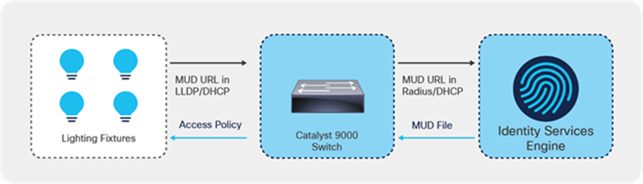
Cisco’s MUD process flows
The figure above shows the MUD process.
● When an IoT device first connects to a network access point, it sends a MUD URL embedded in either the LLDP, DHCP, or 802.1X request.
● The network access device, which for Cisco deployments is restricted to Catalyst switches for now, extracts the URL, encapsulates it in a RADIUS packet, and sends it to the Authentication, Authorization, and Accounting (AAA) server. (When the MUD URL is embedded in a DHCP packet, some networks may instead forward the entire DHCP packet to the AAA server.)
● The AAA server, which for Cisco deployments is the ISE, then passes this URL on to the MUD controller, which is also hosted on the ISE for now.
● The MUD controller then contacts the internet-hosted MUD file server of the manufacturer that this URL points to over HTTPS.
● After verifying that the MUD file was produced by the device manufacturer, the MUD file corresponding to that device is sent to the MUD controller. This file, which is a YANG data model represented as a JSON object, contains abstracted communication intent for the IoT device in question.
● The MUD controller translates this abstract intent to a context-specific policy, which is passed on to the AAA server (ISE).
● The ISE then enforces the policy on the network in the form of PACLs for the point of that IoT device's connection.
● Based on the manufacturer’s stated intent, access to the device is then provided.
9.2. Endpoint requirements for MUD
The endpoint should be capable of sending a MUD URL embedded in either the LLDP, DHCP, or 802.1X request. When enabling MUD functionality on the switch, make sure the third-party lighting vendor is capable of sending the MUD URL.
9.3. MUD configuration on the switch
Below is an outline of the configuration that is required on the switch to enable MUDs. In this case, the lighting fixture is sending the MUD URL via the LLDP TVL 127.
| C93-Standalone#sh device-sensor cache interface g1/0/9 Device: 500b.9100.9116 on port GigabitEthernet1/0/9 ---------------------------------------------------------------------------- Proto Type:Name Len Value Text DHCP 52:option-overload 3 34 01 01 4.. DHCP 54:server-identifier 6 36 04 AC 10 63 35 6.,.c5 DHCP 6:domain-name-servers 10 06 08 AC 10 63 35 AC 1A CA ..,.c5,.J 35 5 DHCP 3:routers 6 03 04 AC 10 0A 01 ..,... DHCP 1:subnet-mask 6 01 04 FF FF FF 00 ...... DHCP 50:requested-address 6 32 04 AC 10 0A 14 2.,... DHCP 0:<unknown> 2 00 00 .. DHCP 255:end 5 FF 03 32 04 AC ..2., DHCP 55:parameter-request-list 7 37 05 01 03 06 0F E5 7.....e DHCP 51:lease-time 6 33 04 00 0A 8C 00 3...^L. DHCP 53:message-type 3 35 01 03 5.. LLDP 0:end-of-lldpdu 2 00 00 .. LLDP 127:organizationally-specific 68 FE 42 00 00 5E 01 68 74 74 .B..^.htt 70 73 3A 2F 2F 6D 75 64 2E ps://mud. 69 67 6F 72 2D 74 65 63 68 igor-tech 2E 63 6F 6D 2F 6D 75 64 2F .com/mud/ 69 67 6F 72 2D 6E 65 74 77 igor-netw 6F 72 6B 6E 6F 64 65 2D 6D orknode-m 75 64 66 69 6C 65 2D 76 31 udfile-v1 2E 6A 73 6F 6E .json LLDP 8:management-address 16 10 0E 07 06 50 0B 91 00 91 ....P.^Q.^Q 16 02 00 00 00 01 00 ....... LLDP 7:system-capabilities 6 0E 04 00 80 00 80 ...^@.^@ LLDP 6:system-description 17 0C 0F 49 67 6F 72 20 4E 6F ..Igor No 64 65 20 58 2E 58 2E 58 de X.X.X LLDP 5:system-name 19 0A 11 49 67 6F 72 20 4E 65 ..Igor Ne 74 77 6F 72 6B 20 4E 6F 64 twork Nod 65 e LLDP 4:port-description 3 08 01 31 ..1 LLDP 3:time-to-live 4 06 02 00 B4 ...4 LLDP 2:port-id 4 04 02 07 31 ...1 LLDP 1:chassis-id 9 02 07 04 50 0B 91 00 91 16 ...P.^Q.^Q. |
● Enable a change of authorization from RADIUS:
| aaa server radius dynamic-author client < radius server – ISE > server-key < key > server-key < key > |
● Enable the Device Sensor to track based on LLDP or DHCP. The Device Sensor configuration is based on Identity Based Networking Services (IBNS) 2.0.
| device-sensor notify all-changes access-session attributes filter-list list mud lldp dhcp access-session accounting attributes filter-spec include list mud access-session monitor |
● Enable LLDP on the switch so that the switch can form an LLDP session to the lighting endpoint.
| lldp run |
● Configure IBNS 2.0 policy to trigger MAC Authentication Bypass (MAB) on the interface.
| policy-map type control subscriber mud event session-started match-all 10 class always do-until-failure 10 authenticate using mab |
● Configure the interface template to scale the configuration of multiple lighting endpoints.
Spanning tree PortFast is a requirement, as the MAB can time out before the port STP changes to the Forward state. Below is the minimum template configuration required for MUD to work.
| template LED1-mud spanning-tree portfast switchport access vlan 10 switchport mode access mab access-session port-control auto service-policy type control subscriber mud |
● Set the RADIUS server preshared key.
| radius server AAA address ipv4 <ISE acting as RADIUS> auth-port 1645 acct-port 1646 key < key > |
● Apply the template to the interface.
| interface GigabitEthernet1/0/24 source template Igor-mud |
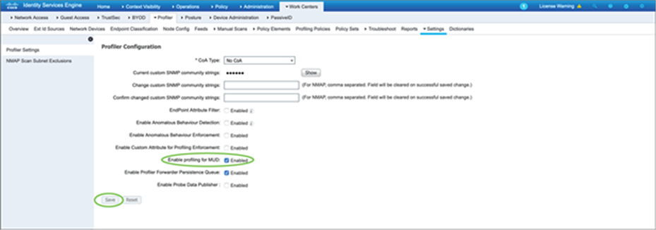
9.4. Configure ISE to classify MUD
Profiling for MUD has to be enabled on the ISE for MUD functionality. It can be enabled in Work Centers à Settings.
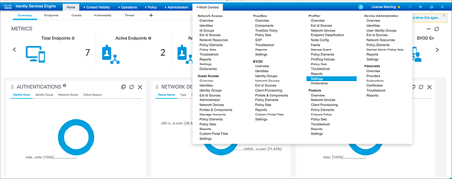
Check “Enable profiling for MUD” and click Save.
Once the endpoint (lighting endpoint in this case) is connected, it will pass the MAB authentication based on the policy that has been defined on the switch.
| C9300#sh access-session interface g1/0/13 details Interface: GigabitEthernet1/0/13 IIF-ID: 0x10FCC723 MAC Address: 500b.9100.3e43 IPv6 Address: fe80::520b:91ff:fe00:3e43 IPv4 Address: Unknown User-Name: 50-0B-91-00-3E-43 Device-type: Un-Classified Device Device-name: Unknown Device Status: Authorized Domain: DATA Oper host mode: multi-auth Oper control dir: both Session timeout: N/A Common Session ID: 156110AC000000AC842E5B83 Acct Session ID: 0x00000005 Handle: 0x070000a2 Current Policy: mud
Server Policies:
Method status list: Method State mab Authc Success |
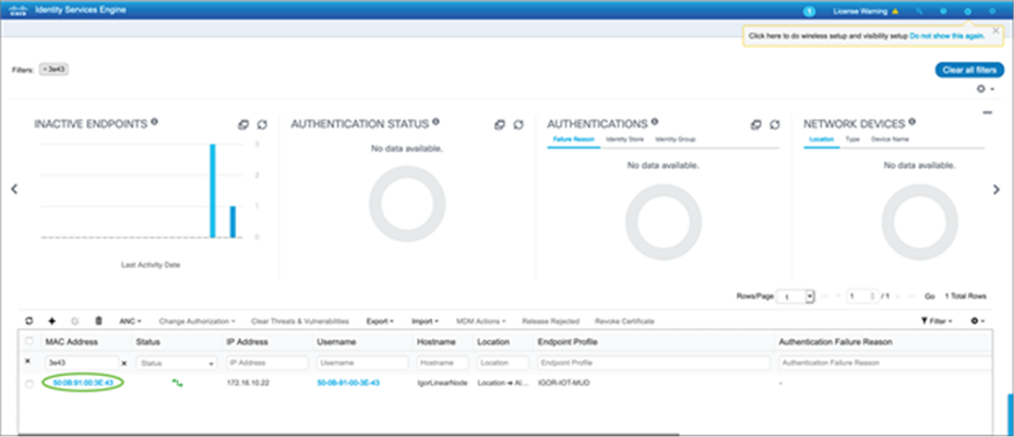
The endpoint will be seen as active and authenticated on ISE in Context Visibility à Endpoints.
9.5. Policy profiling using ISE
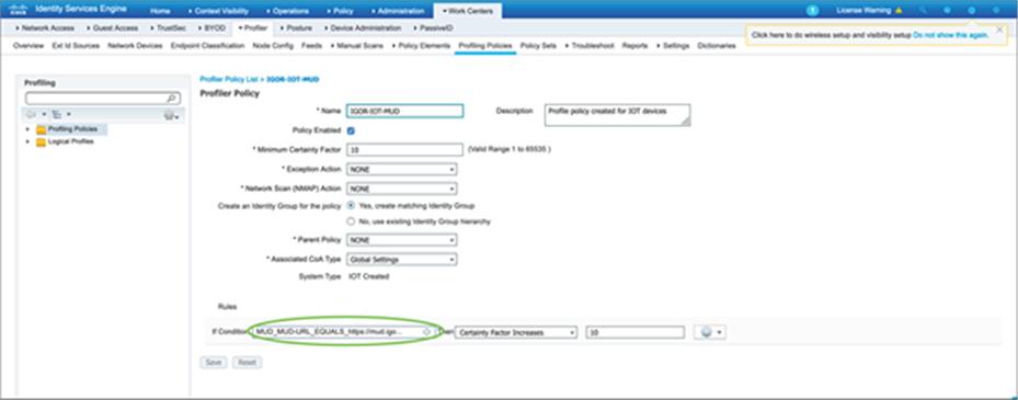
Now that ISE can see and authenticate the client, you can create a profiling policy that matches the MUD URL sent by the lighting fixture. This can be done in Work Centers à Profiler à Profiling Policies.
9.6. Authorization policy using ISE
Authorization policy can be configured in ISE that can dynamically push an ACL to the port where the lighting fixture is connected. This helps limit the communication from the lighting fixture to the control software and other required services that the lighting fixture needs to communicate with. This policy can be defined to a highly granular level, up to limiting access to specific Layer 4 ports, depending on the third-party vendor requirements.
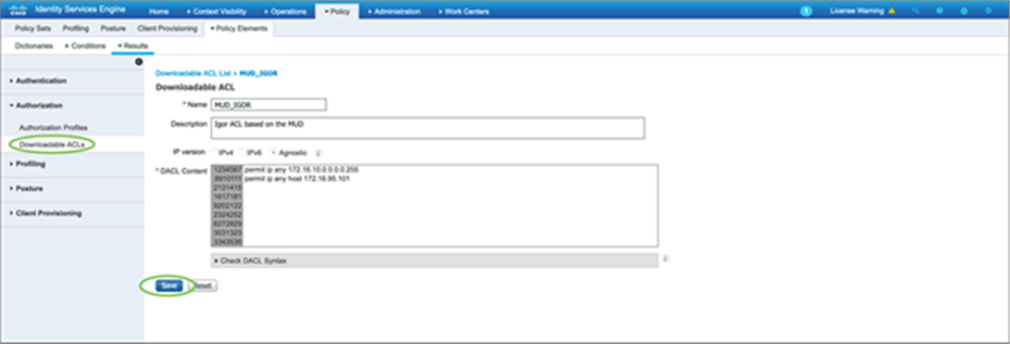
Create an authorization policy that can use the downloadable ACL that was defined earlier.
Enable the authorization policy so that the lighting fixture is authenticated via MAB and a dynamic ACL can be pushed to the Catalyst 9300 Series switch to limit the access by the lighting fixture based on the custom-defined ACL parameters.
| C93-Standalone#sh access-session interface g1/0/13 details Interface: GigabitEthernet1/0/13 IIF-ID: 0x11A479C8 MAC Address: 500b.9100.3e43 IPv6 Address: fe80::520b:91ff:fe00:3e43 IPv4 Address: Unknown User-Name: 50-0B-91-00-3E-43 Device-type: Un-Classified Device Device-name: Unknown Device Status: Authorized Domain: DATA Oper host mode: multi-auth Oper control dir: both Session timeout: N/A Common Session ID: 156110AC000000AB842C1B9A Acct Session ID: 0x00000004 Handle: 0x4a0000a1 Current Policy: mud
Server Policies: ACS ACL: xACSACLx-IP-MUD-5fd16ceb
Method status list: Method State mab Authc Success |
| C93-Standalone# sh ip access-lists xACSACLx-IP-MUD-5fd16ceb Extended IP access list xACSACLx-IP-MUD-5fd16ceb 1 permit ip any 172.16.10.0 0.0.0.255 2 permit ip any host 172.16.95.101 C93-Standalone# |
10. Cisco DNA Center for day-0, day-N operations
Cisco DNA Center has various capabilities built in that help with network design, automation, assurance, provisioning, maintenance, and much more for your devices. In this section, we will cover a few of the various functionalities that Cisco DNA Center allows.
10.1. Cisco DNA Center for day-0 provisioning
This section describes how to provision the Catalyst 9300 Series switch via Cisco DNA Center. There are multiple ways to provision the switch. Here we are going to look at how Plug and Play (PnP) helps with day-0 provisioning.
● For PnP to work successfully, you need a DHCP server with option 43 enabled. Option 43 is used to locate the PnP server, which resides on Cisco DNA Center. For our setup, the DHCP server has already been preconfigured with option 43. This DHCP server assigns an IP address to the switch in addition to providing the location of the Cisco DNA Center (PnP server).
● By default, PnP discovery happens on VLAN 1. Since the management network that we are using in this design is VLAN 100, we have changed the PnP startup VLAN to 100 on the Catalyst 9500 Series switch. The PnP startup VLAN can be changed using the command below:
| pnp startup-vlan 100 |
● Once the switch is powered on initially, the Catalyst 9300 Series switch learns about the PnP server and establishes a secure connection with it.
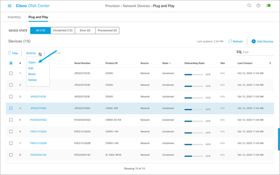
1. The device will be seen in Cisco DNA Center in the Provision section under Plug and Play:
2. On the Plug and Play tab, select the device or devices that need to be claimed.
3. From the Actions menu, select Claim:
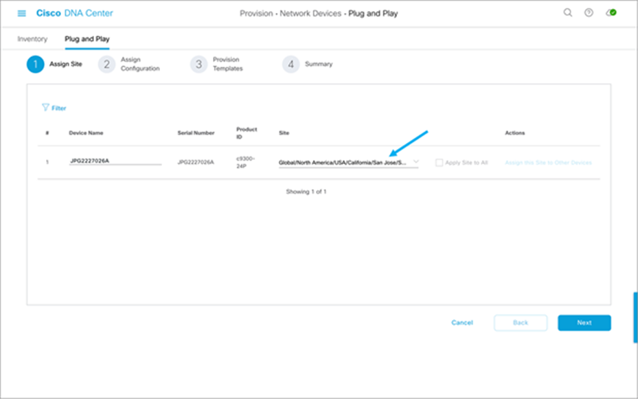
4. Set the Device Name and select the site to which the device is to be assigned, then click Next:
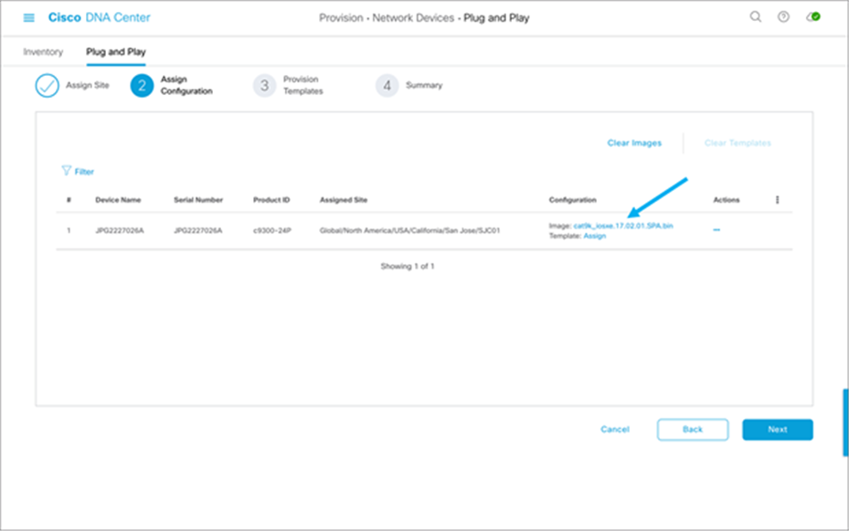
5. Select the software image and/or the template you wish to assign to the device, then click Next:
6. You may check the day-0 configuration by clicking “Preview Day-0 Config,” then click Continue.
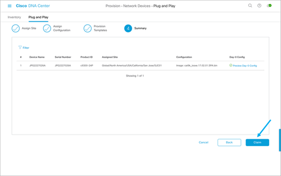
7. Verify that the device is claimed.
More details and workflows regarding PnP using Cisco DNA Center can be found in the Network Device Onboarding Deployment Guide.
10.2. Software update via Cisco DNA Center
The software image of the switch can be updated using Cisco DNA Center. The image must be downloaded and loaded into the Cisco DNA Center repository beforehand and marked as the Golden Image. Once that is done, the task of updating the image simply involves clicking a few buttons. The steps are as follows:
1. Go to the Inventory of devices within Cisco DNA Center.
2. Select the devices that are to be updated.
3. After selecting the devices, click the Action menu, choose Software Image, and then Update Image.
4. Decide when to update the image (it can be updated now or scheduled for a later time). Then click Next.
5. Select when to activate the image.
6. Verify the checks that will be performed for validation.
7. Verify the checks and activation timing. Then click Confirm.
10.3. Device discovery after initial installation
This section applies if the device has already been installed and needs to be integrated into Cisco DNA Center. To get Assurance benefits via Cisco DNA Center, NETCONF needs to be configured on the access switches to which the PoE devices are connected. Cisco DNA Center pushes the required telemetry configuration to the switch for PoE Assurance after the device is discovered successfully.
1. Enable NETCONF on the switch prior to discovery.
| Netconf-yang |
2. Navigate to the Discovery section.
3. Either choose Add Discovery or edit an existing discovery.
4. Add NETCONF into discovery.
5. Verify the successful integration of NETCONF between the Catalyst 9300 Series switch and Cisco DNA Center.
6. Verify that the following NETCONF telemetry (subscriptions 500 and 501) was pushed to the Catalyst 9300 Series switch:
| C9300#show run | sec telemetry telemetry ietf subscription 500 encoding encode-tdl filter tdl-uri /services;serviceName=ios_oper/poe_port_detail source-address 192.168.100.2 stream native update-policy periodic 60000 receiver ip address 172.16.99.97 25103 protocol tls-native profile sdn-network-infra-iwan telemetry ietf subscription 501 encoding encode-tdl filter tdl-uri /services;serviceName=ios_oper/poe_module source-address 192.168.100.2 stream native update-policy periodic 60000 receiver ip address 172.16.99.97 25103 protocol tls-native profile sdn-network-infra-iwan |
11. Cisco DNA Center for PoE assurance
Cisco DNA Center allows for easy viewing and assessment of real-time analytical data of the connected PoE devices. Information includes the PoE device operational state, PoE powered device power distribution, various PoE insights, and power load distribution (see Figure 14).
POE Assurance dashboard
11.1. PoE operational state distribution
Within the PoE Assurance dashboard, you can see various information for the PoE devices. For example, by clicking the View Details link in the PoE Operational State Distribution section, you see the states of the various PoE endpoints connected to your switch (see Figure 15). You can view a timeline of when and where a fault occurred with an endpoint, view information on which devices are connected to which Catalyst 9300 Series switches, and view various PoE data such as allocated power and power consumed by the PoE endpoint (see Figure 16).
POE Operational State Distribution timeline
PoE Operational State Distribution details
11.2. PoE powered device distribution
Another section within the PoE Assurance dashboard is PoE Powered Device Distribution. By clicking View Details in this section, you can view the PoE endpoint power distribution on the switches (see Figure 17). You can also view how many devices are within which allocated power segments, allowing for an easy view and assessment of power load distribution.
PoE Powered Device Distribution graph
Within the PoE Insights section of the POE Assurance dashboard, you can also see a graphical view of the various PoE endpoints that are connected to your switch (see Figure 18). You can see the various device types and their power state, allowing for easy troubleshooting of vendor-specific endpoints.
A view of the different PoE endpoint types
Power load management on the Catalyst 9300 Series switches can also be easily managed and assessed via Cisco DNA Center. Within the Power Load Distribution dashboard, you can view a timeline of power consumption as a percentage per Catalyst 9300 Series device (see Figure 19). Furthermore, you can see an exact percentage of power load and the total power budget per switch (see Figure 20).
Power load distribution on Catalyst 9300 Series switches
Power load distribution per switch
11.5. PoE port verification on switch
With the help of Cisco DNA Center, verification of which ports are currently powering PoE devices is made simple. In Cisco DNA Center, you can see a graphical representation of which ports on the Catalyst 9300 Series are powered on and supplying PoE to endpoints. Furthermore, you can view the port speed, PoE status, and much more in the details for each port on this page (see Figure 21).
View of which switch ports have PoE enabled
12. Troubleshooting PoE on Catalyst 9000 switches
This section covers the basic troubleshooting steps for resolving PoE issues seen on Catalyst 9000 switches.
Troubleshooting of PoE endpoints is made simpler with a GUI with the help of Cisco DNA Center. You can view an instance of a PoE endpoint and see the various data specific to that device (see Figure 22). You can view the various issues related to the device, and Cisco DNA Center will also help you resolve those issues by recommending possible resolutions to the particular issues and allowing you to resolve them within Cisco DNA Center by giving you the option to push particular CLI commands to the Catalyst 9300 Series switch (see Figure 23).
Furthermore, you get a timeline view of when major events occurred to the PoE endpoint, how critical they were, the reason for the failure, and much more (see Figure 22).
PoE endpoint health
Resolutions to PoE device issue
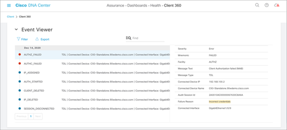
Reason for PoE device failure
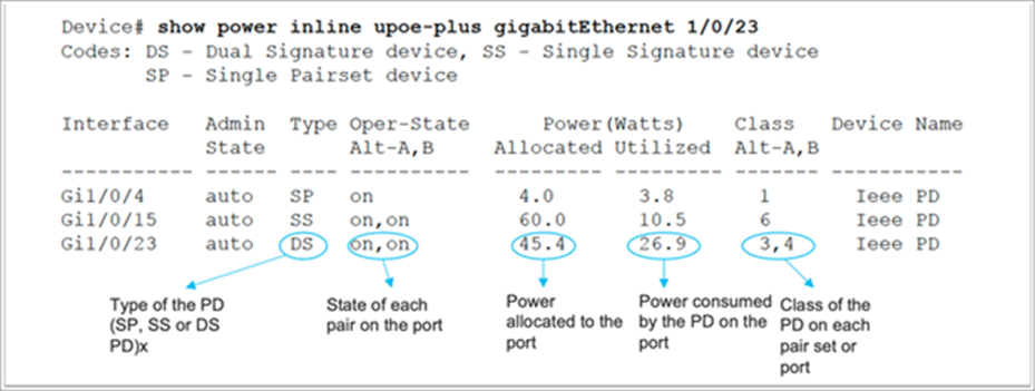
Displaying 802.3bt relevant information
A show power inline upoe-plus command has been added to display the 802.3bt relevant information. The output will show 802.3bt-specific information such as PD type, state of each pair on the port, power allocated to the port, and power consumed by the PD.
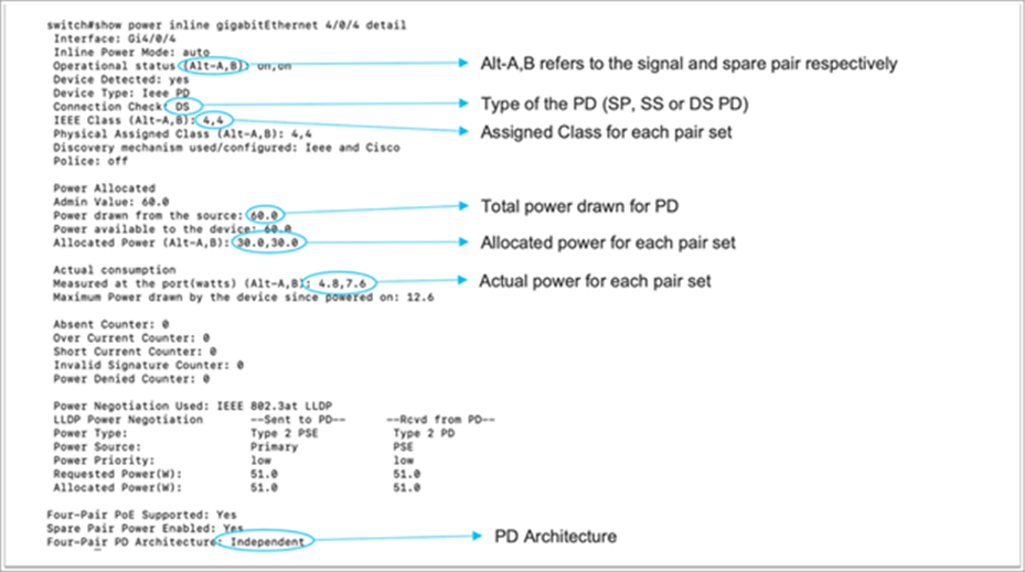
For more detail information, the show power inline detail command can be used:
PoE power-on self-test (POST)
The POST performs a PoE controller functionality test to check the chip accessibility, firmware download, and health status of the PSE.
| C9K#show post Stored system POST messages: Switch 1 --------- **snip** POST: Inline Power Controller Tests : Begin <++ PoE related test POST: Inline Power Controller Tests : End, Status Passed <++ Desirable outcome |
This test is run only during the bootup of the switch. For any failed status in POST results, contact Cisco TAC for further troubleshooting.
PoE diagnostics
With online diagnostics, you can test and verify the hardware functionality of a device while the device is connected to a live network. Online diagnostics contain packet-switching tests that check different hardware components and verify the data path and control signals. Online diagnostics detect problems related to components such as:
● PoE hardware components
● Interfaces
● Solder joints and board integrity
A TestPoE diagnostic test can be used to detect hardware problems. These can be run on demand. This is a disruptive test and is off by default. Do not start this diagnostic test during normal switch operation unless recommended/assured by TAC. This test can be run if you experience PoE controller issues with a port, and it can be run only as an on-demand test.
| C9300#diagnostic start switch 1 test DiagPoETest <++ 1 is switch number, use respective switch number in question Diagnostic[switch 1]: Running test(s) 8 may disrupt normal system operation and requires reload Do you want to continue? [no]: yes << use with caution, this is disruptive test C9348U-1# *Mar 7 06:28:39 CET: %DIAG-6-TEST_RUNNING: switch 1: Running DiagPoETest{ID=8} ... *Mar 7 06:28:39 CET: %DIAG-6-TEST_OK: switch 1: DiagPoETest{ID=8} has completed successfully
C9300#show diagnostic result switch 1 test DiagPoETest Current bootup diagnostic level: minimal Test results: (. = Pass, F = Fail, U = Untested) 11) DiagPoETest ---------------------> . <++ expected result is pass "." |
For any PoE-related issues, gather the output from the following show tech-support command:
| C9300#show tech-support poe | redirect flash:showtechpoe9400.txt |
Controller port error
A port error reported by the PoE controller is detected by the Cisco switch. Controller errors have some common variants.
| %ILPOWER-3-CONTROLLER_PORT_ERR: Controller port error, Interface Te3/0/1: Power Controller reports power Imax error detected |
An Imax error occurs when a PoE-capable port on the switch draws more power than it negotiated. Additionally, some third-party devices might have an excessive surge in current when first connected to a PoE port, which could trigger an Imax error.
Please make sure that attached PDs are IEEE compliant.
ILPOWER_POWER_DENY error
| %ILPOWER-5-IEEE_DISCONNECT: Interface Gi1/0/1: PD removed %ILPOWER-7-DETECT: Interface Gi1/0/1: Power Device detected: IEEE PD %ILPOWER-5-ILPOWER_POWER_DENY: Interface Gi1/0/1: inline power denied. Reason: insufficient power |
This error means that there is not enough power remaining in the switch to supply the PoE port. This is likely due to total inline power being greater than available power. Verify power budgeting, and install more power supplies if needed. Changing power supply redundancy from redundant to combined will also help. For stacked systems, consider StackPower to pool total power across switches.
Controller POST error
| %ILPOWER-3-CONTROLLER_POST_ERR: Inline Power Feature is disabled on this switch because Power On Self Test (POST) failed on this switch. |
This error means the switch decided to shut off PoE because the POST for the switch failed. Verify the PoE controller functionality test to learn the health status of the PSE.
The table below summarizes the high-level features validated as part of this deployment guide.
Table 6. Features covered in this guide
| Role |
Test |
|
| Access layer |
UPOE+ negotiation |
✓ |
| Interface template |
✓ |
|
| Autoconf |
✓ |
|
| Distribution/core |
DHCP relay |
✓ |
| SVL failover |
✓ |
|
| PoE |
UPOE+ |
✓ |
| Fast PoE |
✓ |
|
| Perpetual PoE |
✓ |
|
| PoE port priority |
✓ |
|
| Load shedding |
✓ |
|
| Management |
Switch onboarding (PnP) |
✓ |
| Switch upgrade |
✓ |
|
| PoE Assurance |
✓ |
|
| PoE troubleshooting |
✓ |
|
| Security |
DHCP snooping |
✓ |
| BPDU Guard |
✓ |
|
| ARP Inspection |
✓ |
|
| Storm control |
✓ |
|
| Port access list |
✓ |
|
| ISE integration |
✓ |
|
| MUD |
✓ |
|
| 802.3bt 90W capable lights |
802.3bt negotiation |
✓ |
| Light brightness control |
✓ |
|
| Light discovery from management software |
✓ |
|
| Firmware upgrade |
✓ |
|
| Third-party management software |
✘ |
|
| 802.3bt 90W capable USB-C dongle |
802.3bt negotiation |
✓ |
| Network connectivity |
✓ |
The following vendor-specific lighting endpoints have been used in this deployment guide.
● Igor
● Molex
Anker and Bizlink USB-C 90W-capable dongles have also been used in this deployment guide.