Cisco Catalyst 9800 FlexConnect Branch Deployment Guide
Available Languages
Bias-Free Language
The documentation set for this product strives to use bias-free language. For the purposes of this documentation set, bias-free is defined as language that does not imply discrimination based on age, disability, gender, racial identity, ethnic identity, sexual orientation, socioeconomic status, and intersectionality. Exceptions may be present in the documentation due to language that is hardcoded in the user interfaces of the product software, language used based on RFP documentation, or language that is used by a referenced third-party product. Learn more about how Cisco is using Inclusive Language.
- US/Canada 800-553-2447
- Worldwide Support Phone Numbers
- All Tools
 Feedback
 Feedback
This document describes how to deploy a Cisco FlexConnect® wireless branch solution on the Cisco Catalyst™ wireless platform. The Catalyst wireless platform is available in two flavors, the virtual form factor and a hardware appliance.
The virtual form factor can be deployed on any x86 server that supports hypervisor such as VMware ESXi, KVM, etc. To get the list of supported hypervisors and the versions, please refer to the deployment guide of the Catalyst wireless family. The virtual form factor can be deployed on-prem with an enterprise or can be installed on cloud providers such as AWS.
The Catalyst 9800 Wireless Controller is the hardware appliance for the Catalyst wireless family. The Catalyst 9800WC and virtual cloud controller run on the Cisco IOS® XE software base, utilizing the flexibility and modularity available with the platform.
Refer to the following documentation for how to get started on the Catalyst 9800 and cloud-based virtual wireless LAN controller.
The documents cover the features that are supported on the following platforms and releases.
Catalyst wireless platforms
11ac Wave 1 and Wave 2 Access Points - 18xx, 2802, 3802, 4800, 1540, 1560, 1700, 2700, 3700, 1570
11ax Access Points - 9105, 9115, 9117, 9120, 9130
IOS-XE 16.10 and higher.
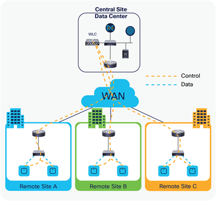
FlexConnect Architecture and Traffic Flow
FlexConnect is a wireless solution for branch office and remote office deployments.
The FlexConnect solution enables the customer to:
● Centralize control and manage the traffic of APs from the data center
● Distribute the client data traffic at each branch office
Advantages of centralizing access point control traffic
● Single pane of monitoring and troubleshooting
● Ease of management
● Secured and seamless mobile access to data center resources
● Reduction in branch footprint
● Increase in operational savings
Advantages of distributing client data traffic
● No operational downtime (survivability) against complete WAN link failures or controller unavailability
● Mobility resiliency within branch during WAN link failures
● Increase in branch scalability; supports branch sizes that can scale up to 100 APs and 250,000 square feet (5000 square feet per AP)
The Cisco FlexConnect solution also supports central client data traffic. The table below defines the supported Layer 2 and Layer 3 security types only for central-switched and local-switched users.
Table 1. L2 security support for centrally and locally switched users
| WLAN L2 security |
Type |
Result |
| None |
N/A |
Allowed |
| WPA + WPA2 |
802.1x |
Allowed |
| CCKM |
Allowed |
|
| 802.1x + CCKM |
Allowed |
|
| PSK |
Allowed |
|
| 802.1x |
WEP |
Allowed |
| Static WEP |
WEP |
Allowed |
| WEP + 802.1x |
WEP |
Allowed |
Table 2. L3 security support for centrally and locally switched users
| WLAN L3 security |
Type |
Result |
| Web authentication |
Internal |
Allowed |
| External |
Allowed |
|
| Customized |
Allowed |
|
| Web pass-through |
Internal |
Allowed |
| External |
Allowed |
|
| Customized |
Allowed |
|
| WEP |
Allowed |
|
| Splash page web redirect |
WEP |
Allowed |
FlexConnect modes of operation
Table 3. Flexconnect modes of operation
| FlexConnect mode |
Description |
| Connected |
FlexConnect is said to be in connected mode when its CAPWAP control plane back to the controller is up and operational, meaning the WAN link is not down. |
| Standalone |
Standalone mode is specified as the operational state the FlexConnect enters when it no longer has the connectivity back to the controller. FlexConnect APs in standalone mode will continue to function with last known configuration, even in the event of power failure and WLC or WAN failure. |
FlexConnect APs are deployed at the branch site and managed from the data center over a WAN link. The maximum transmission unit (MTU) must be at least 500 bytes.
Table 4. FlexConnect WAN Bandwidth and latency requirements
| Deployment type |
WA bandwidth (min) |
WAN RTT latency (max) |
Max APs per branch |
Max clients per branch |
| Data |
64 Kbps |
300 ms |
5 |
25 |
| Data |
640 Kbps |
300 ms |
100 |
1000 |
| Data |
1.44 Mbps |
1 sec |
100 |
1000 |
| Data + voice |
128 Kbps |
100 ms |
5 |
25 |
| Data + voice |
1.44 Mbps |
100 ms |
100 |
1000 |
| Monitor |
64 Kbps |
2 sec |
5 |
N/A |
| Monitor |
640 Kbps |
2 sec |
100 |
N/A |
Note: It is highly recommended that the minimum bandwidth restriction remains 12.8 Kbps per AP, with the round-trip latency no greater than 300 ms for data deployments and 100 ms for data + voice deployments.
Refer to the FlexConnect matrix document in the link below to validate the list of supported features.
Wireless branch network design
The rest of this document highlights the guidelines and describes the best practices for implementing secured distributed branch networks. FlexConnect architecture is recommended for wireless branch networks that meet the following design requirements.
● Branch size that can scale up to 100 APs and 250,000 square feet (5000 square feet per AP)
● Central management and troubleshooting
● No operational downtime
● Client-based traffic segmentation
● Seamless and secured wireless connectivity to corporate resources
● PCI compliant
● Support for guests
Branch customers find it increasingly difficult and expensive to deliver full-featured scalable and secure network services across geographic locations. To support customers, Cisco is addressing these challenges by introducing the FlexConnect deployment mode.
The FlexConnect solution virtualizes the complex security, management, configuration, and troubleshooting operations within the data center and then transparently extends those services to each branch. Deployments using FlexConnect are easier for IT to set up, manage, and, most importantly, scale.
● Increase scalability with 6000 AP support
● Increased resiliency using FlexConnect fault tolerance
● Increase segmentation of traffic using FlexConnect (central and local switching)
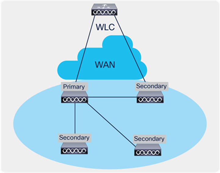
● Ease of management by replicating store designs using different policy profiles and site tags per store while maintaining the same WLAN profile as seen in the figure below
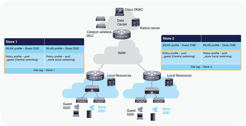
Design replication across stores by mapping different site tags and policy tags
Features addressing branch network design
The rest of the sections in this guide capture feature usage and recommendations to realize the typical branch network design.
Table 5. Features addressing branch network design
| Features |
Highlights |
| New config model on Catalyst wireless family |
Ability to decouple and modularize the configuration entities. This enables you to have the same configuration across different stores by having the same profiles across stores and using a different tag for each store. |
| Fault tolerance |
Improves the wireless branch resiliency and provides no operational downtime. |
| Client limit per WLAN |
Limiting total guest clients on branch network. |
| Auto-convert APs in FlexConnect |
Assigning a site tag that has a flex profile will auto-convert the AP to FlexConnect mode without user intervention. |
| Efficient AP image upgrade |
Reduces downtime when upgrading your branch. Efficient AP upgrade saves WAN bandwidth and enables a branch AP to upgrade at a much faster pace. |
| Guest access |
Continue existing Cisco’s guest access architecture with FlexConnect by having a central switched SSID that is a tunnel to a controller in the DMZ zone. |
| URL ACL |
Ability to support use cases of bring your own device (BYOD) at the branch |
| Backup radius server |
Provides resiliency at the branch due to WAN outage |
| AAA override |
Provides segmentation and polices per user |
Cisco Catalyst wireless config model
This section describes the new config model introduced in the Catalyst wireless platforms.
The new config model goes towards the modularized and reusable model with logical decoupling of configuration entities.
The model introduces the uses of tags and profiles. The below table gives an overview of the tags and profiles used within the new Catalyst wireless products.
Table 6. Tags on Profile on the Catalyst 9800 controller
| Tags and profile |
Highlights |
| WLAN profile |
Creation of WLAN with the corresponding security. Addition of AAA entities and configuring the advanced capabilities of the WLAN. |
| Policy profile |
Defines the policy of the WLAN such as central /local switching, ACL, VLAN mapping for the WLAN, QOS, AAA policy, and export anchor. |
| Policy tag |
Defines the mapping of the WLAN to the policy profile. |
| Flex profile |
Flex profile defines the WLAN to VLAN mapping for flex deployment, ACL mapping, and radius server configuration. |
| AP join profile |
Defines the CAPWAP and AP parameters related to join procedures. |
| RF profile/RF tag |
RF characteristics of the site mapped to an RF tag. |
| Site tag |
Site tags maps the flex profile and the AP join profile. |
| AP tag |
Maps the policy tag, site. and RF tag on to the AP. |
The model follows the design and provision theme.
The design phase involves creating the elements necessary for the wireless networks such as wireless SSID, policy management, RF tagging flex profile, etc. The deployment phase is where the designed elements are provisioned on the AP.
Profiles represent a set of attributes that are applied to the clients associated with the APs. Profiles are reusable entities that can be used across tags. Profiles (used by tags) define the properties of the AP or associated clients.
There are different kinds of profiles depending on the characteristics of the entities they define. These profiles are in turn part of a larger construct called a tag.
A tag’s property is defined by the property of the profiles associated with it. This property is in turn inherited by an associated client/AP. There are various types of tags, each associated with different profiles.
No two types of tags include profiles having common properties. This helps eliminate the precedence amongst the configuration entities to a large extent. Every tag has a default that is created when the system boots up.
WLAN profile
The WLAN profile defines the properties of a WLAN such as profile name, status, WLAN ID, L2 and L3 security parameters, AAA server associated with this SSID, and other parameters that are specific to a particular WLAN.
Policy profile
The policy profile is an entity that comprises of network and switching policies for a client, except for QoS, which constitute the AP policies as well.
The policy profile is a reusable entity across tags. Anything that is a policy for the client applied on the AP/controller is moved to the policy profile — for example, VLAN, ACL, QOS, session timeout, idle timeout, AVC profile, bonjour profile, local profiling, device classification, etc.
The WLAN profile and policy profile are both part of a policy tag and define the characteristics and policy definitions of a set of WLANs. The intent of decoupling the policies from the SSID, even though it is a one-to-one mapping, is to give more flexibility to the admin in configuring site-based policies (local or remote) while keeping the WLAN definition common.
Policy tag
Policy tag constitutes the mapping of WLAN profiles to policy profiles. The policy profile defines the network policies and the switching policies for a client (with the exception of QoS, which constitutes the AP policy as well as the client policy).
A default policy tag with WLAN profiles with a WLAN ID <16 is mapped to a default policy profile.
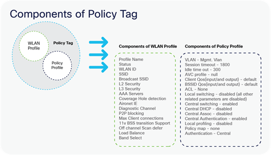
Components of Policy Tag
AP join profile
The following parameters will be part of the AP join profile – CAPWAP IPV4/IPV6, UDP lite, high availability, retransmit config parameters, global AP failover, hyper-location config parameters, Telnet/SSH, 11u parameters, etc. For AP join profile changes, a small subset requires the CAPWAP connection to be reset since these parameters pertain to the characteristics of the AP.
Flex profile
The flex profile contains the remote site-specific parameters — for example, the primary and secondary AP list, the EAP profiles that can be used for the case where AP acts as an authentication server, local radius server information, VLAN-ACL mapping, etc. There is no default flex profile; however, a custom flex profile can be added to the default site tag.
The AP join profile and flex profile are both part of a site tag and define the characteristics of a local or remote site.
Site tag
The site tag constitutes two profiles, the flex profile and the AP join profile. The site tag defines the properties of a site, both central as well as remote (FlexConnect) site. The attributes of a site that are common across the central and remote sites are part of the AP join profile. The attributes that are specific to the flex/remote site are part of the flex profile.
The default site tag constitutes the default AP join profile. There is no default flex profile. The default AP join profile values will be the same as that for the global AP parameters today plus a few parameters from the AP group in today’s configuration like “preferred mode,” 802.11u parameters, location, etc.
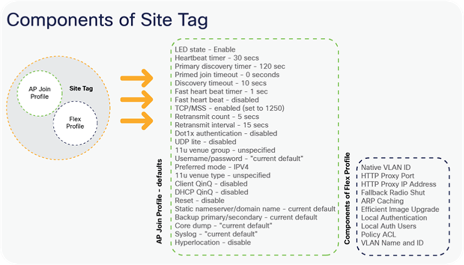
Components of Site Tag
RF profile
By default, there exist two default RF profiles (one for 802.11a and one for 802.11b). RF profiles constitute the RF-specific configurations such as data rates, MCS settings, power assignment, DCA parameters, CHDM variables, and HDX features. One 802.11a RF profile and one 802.11b RF profile can be added to an RF tag.
RF tag
The RF tag constitutes the 11a and 11b RF profiles. The default RF Tag constitutes the default 802.11a RF profile and the default 802.11b RF profile.
The default 11a RF profile and 11b RF profile contain default values for global RF profiles for the respective radios.
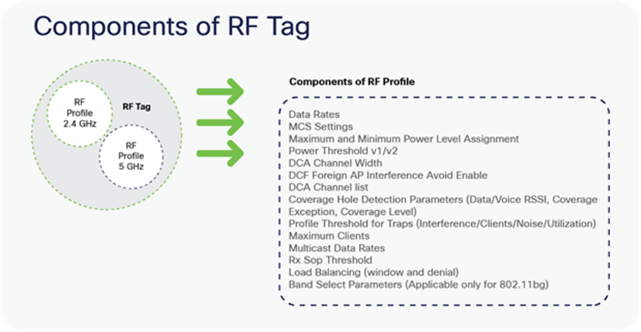
Components of RF Tag
AP tag
Access points are tagged based on the SSIDs and the associated policies they broadcast by associating a policy with the AP, the site it belongs to, and the RF characteristics desired for that access point by mapping the respective tags. Once tagged, the AP gets a list of WLANs to be broadcasted along with the properties of the respective SSIDs, properties of the local/remote site, and the RF properties of the network.
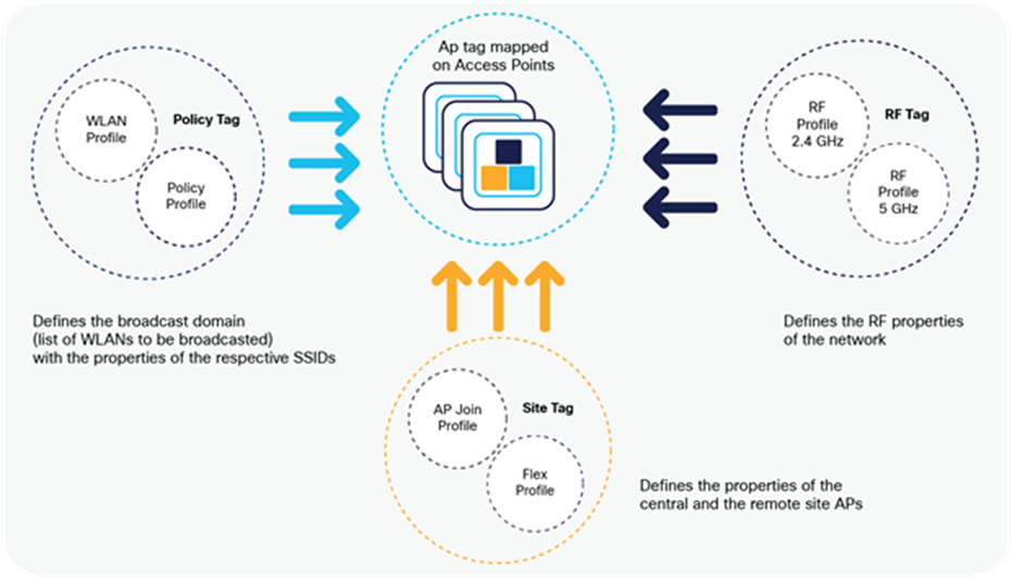
Tags and Profiles association and mapping relationship
There are three different options for an administrator to accomplish the flow of creating profiles and tags:
● Use of the basic wireless setup wizard
● Use of advanced wireless setup wizard
● Manual configuration
Please refer to the controller deployment guide for controller bring-up, SVI creation, and management of GUI access.
The following sections will cover the method and ways a profile and tags can be configured on the Catalyst wireless platforms. An example of a store that has the following deployment model will be used to showcase the configuration model.
A store SSID that has a WPA-PSK security enabled to connect the handhelds used in a store — the SSID would be locally switched.
A guest SSID that is centrally switched.
An enterprise SSID for employees that has dot1x enabled and uses radius server for authentication.
Table 7. Deployment scenario examples
| SSID |
Security |
Switching |
| Store-SSID |
WPA-PSK |
Local |
| Web-auth |
Central |
|
| Enterprise SSID |
Wpa-2/dot1x |
Local |
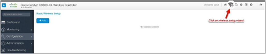
In the basic wireless setup wizard, we will cover the use of creating a store SSID with WP-PSK security.
Procedure
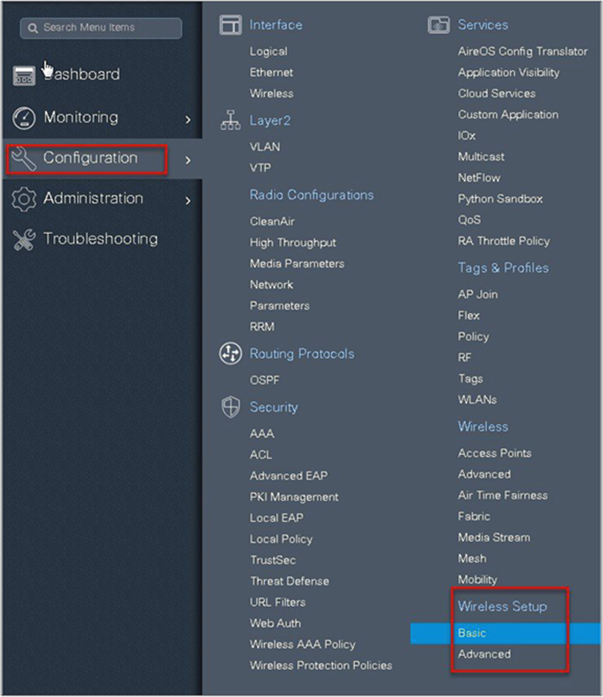
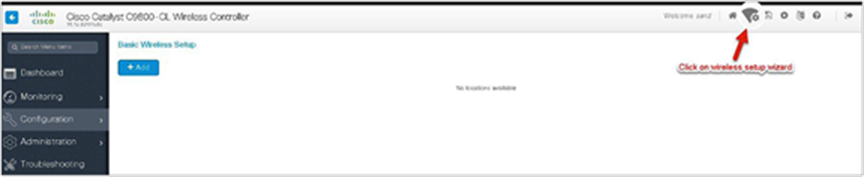
Step 1. Click on the wireless setup wizard.
Step 2. Select the basic setup wizard from the drop-down box and click on “Add.”
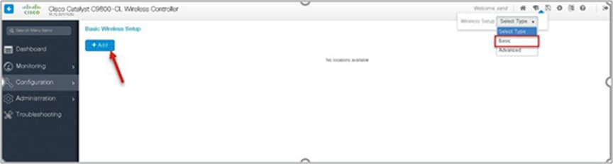
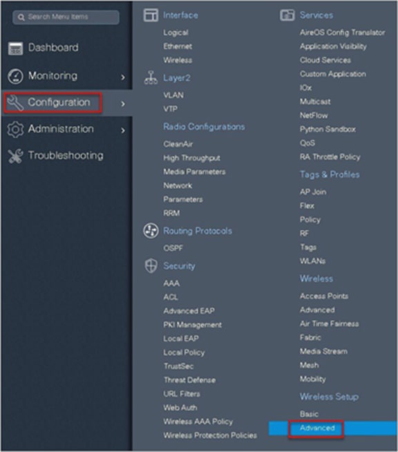
An administrator can also start the wizard by navigating to Configuration > Wireless Setup > Basic.
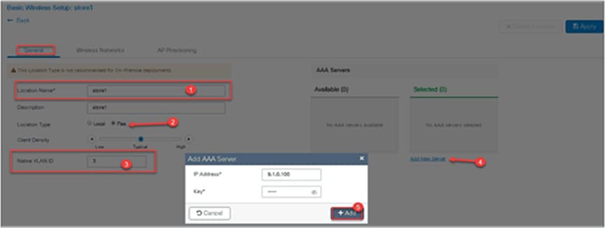
Step 3. Select a name for the remote site, and specify the location type as flex for branch deployments.
The native VLAN ID refers to the native VLAN ID pushed to the AP. The AAA server defines the radius server address pushed to the AP in the branch for local authentication.
To add a new server, click on “Add New server” and specify an IP address and a secret key.
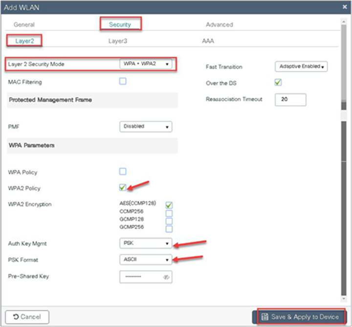
Step 4. Click on the wireless network to create an SSID along with the policy.
To create a new WLAN, click on “Define New.”
Define the security for the WLAN (for reference, an SSID with PSK is created here).

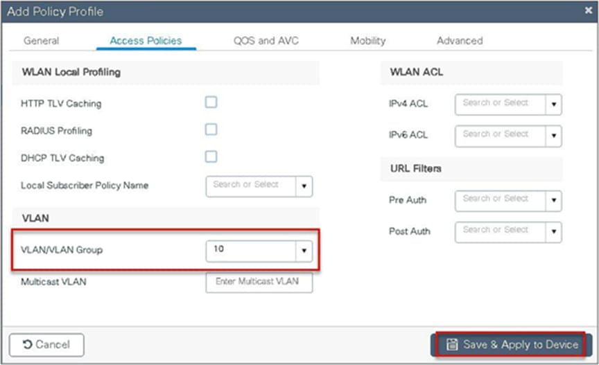
Step 5. Define the policy for the WLAN.
The VLAN/VLAN group defines the VLAN used by the SSID.

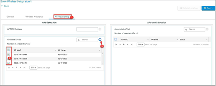
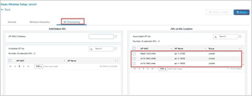
Step 6. Click on the AP provisioning to provision the SSID and policy profile on the selected AP.
Once the AP is provisioned, the AP gets converted to flex mode based on the site tag assigned to the AP.
If the AP is already in flex mode, there is no conversion. If the AP is in local mode, the AP will reboot to boot in FlexConnect mode.
Step 7. Click apply to complete the wizard.
Advanced wireless setup wizard
In this section, the advance config wizard is used to create a guest SSID with web authentication, which would be centrally switched through a WLC at the data center.
Procedure
Step 1. Click on the wireless setup wizard.
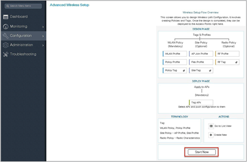
Step 2. Select the advanced option.
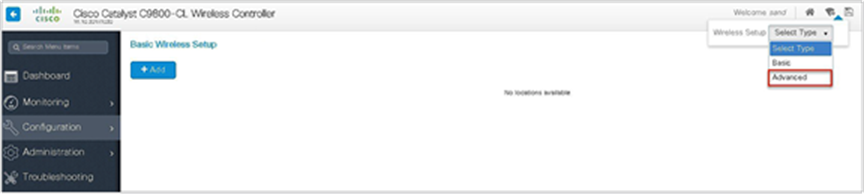
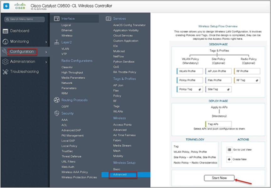
An administrator can also start the wizard by navigating to Configuration > Wireless Setup > Advanced.
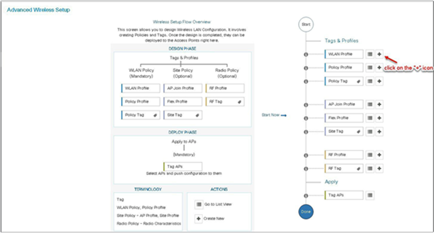
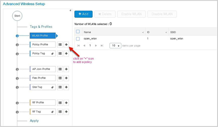
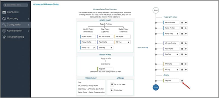
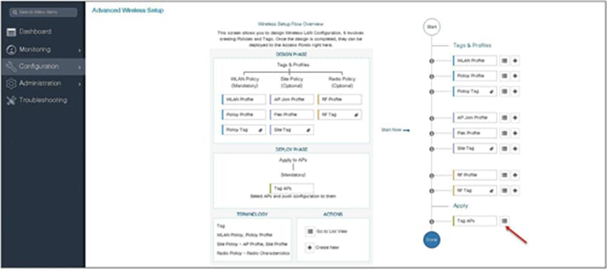
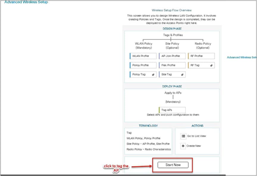
Step 3. The advanced config wizard gives an overview of the flow of tags and policies. Click on the “Start Now” button to start the wizard.
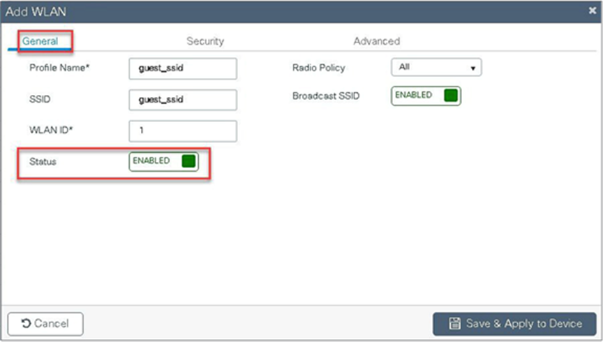
Step 4. Click on the “+” icon to start creating the WLAN.
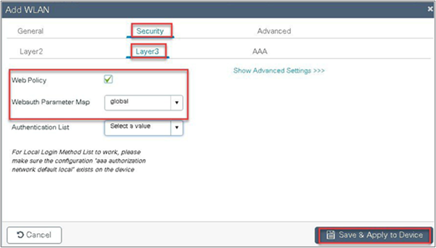
Step 5. Define the SSID name and security type for the WLAN.

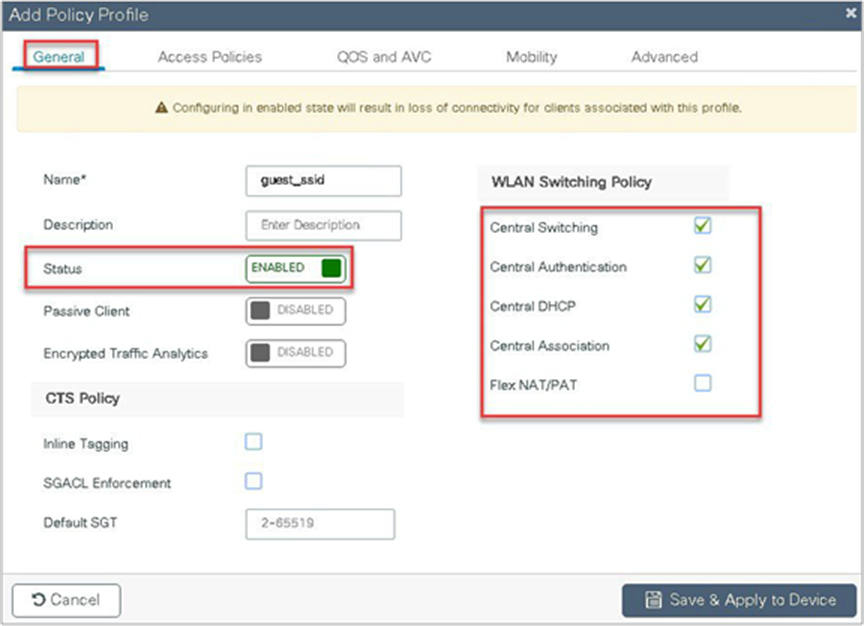
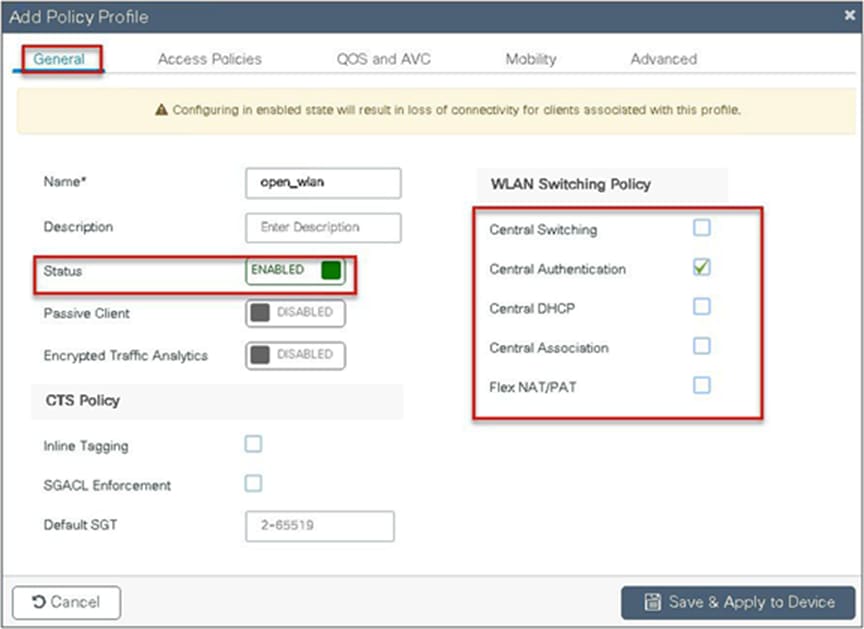
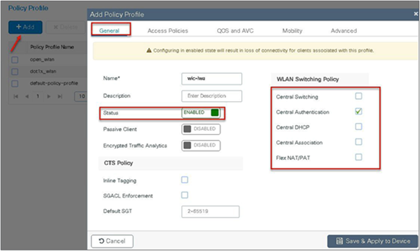
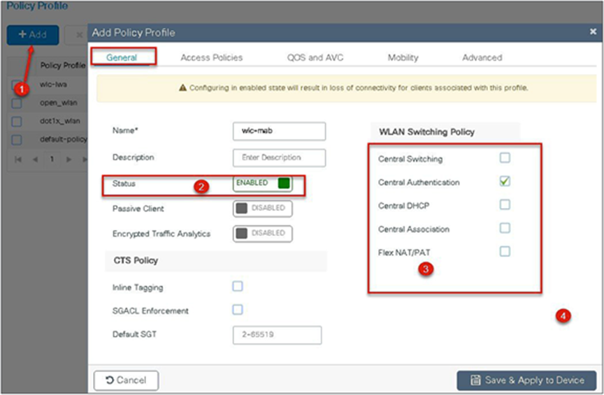
Step 6. Create a policy profile for the SSID.
Define the policy profile to be central switched and central authentication.
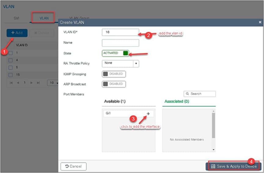
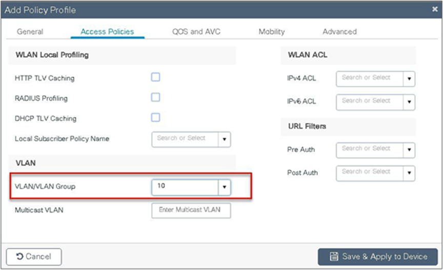
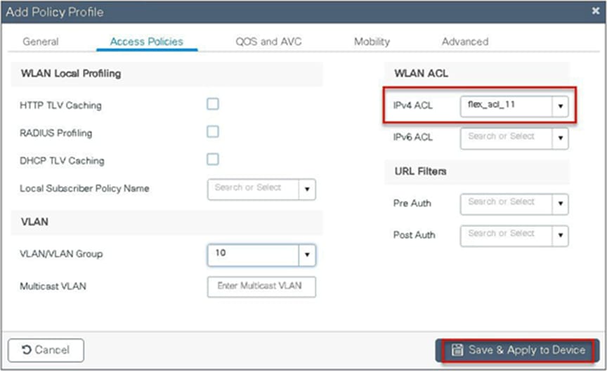
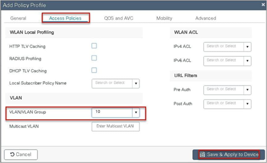
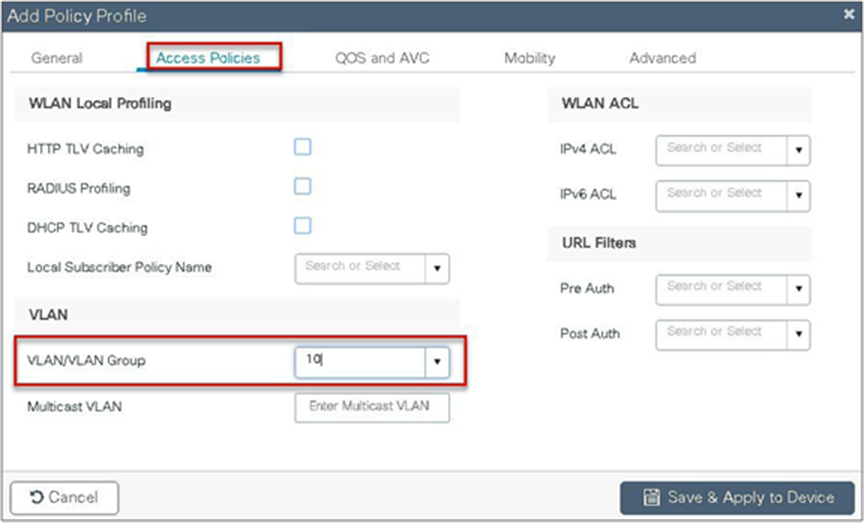
Step 7. Define a VLAN for the SSID under the access policies. In the example below, the VLAN 10 is mapped on the policy profile.
The controller also needs a Layer 2 VLAN or a Layer 3 SVI to be created to centrally switch the traffic from the controller.
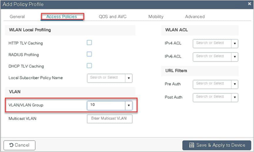
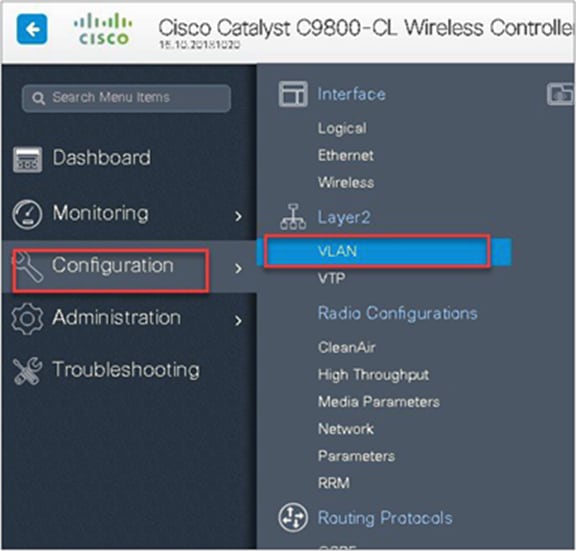
In this example, we create a Layer 2 VLAN on the controller.
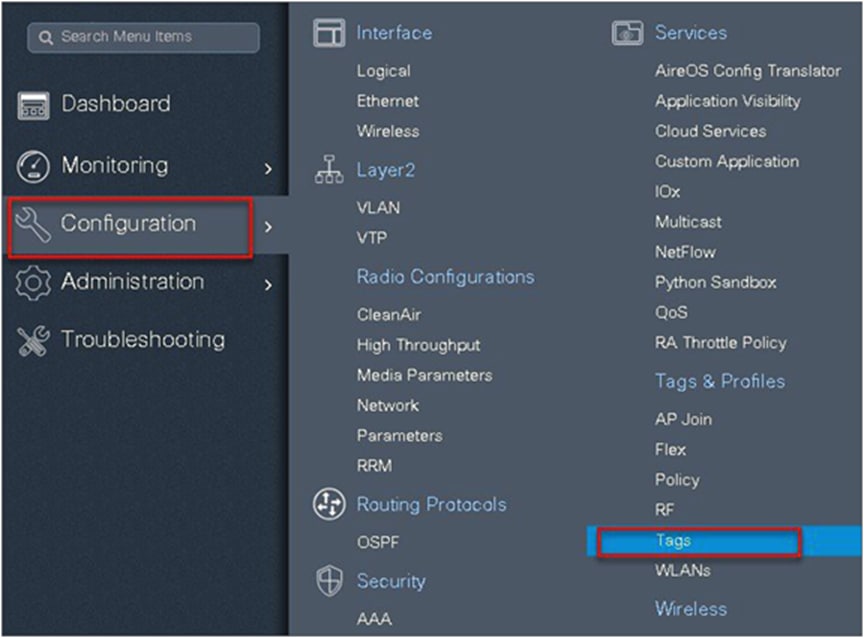
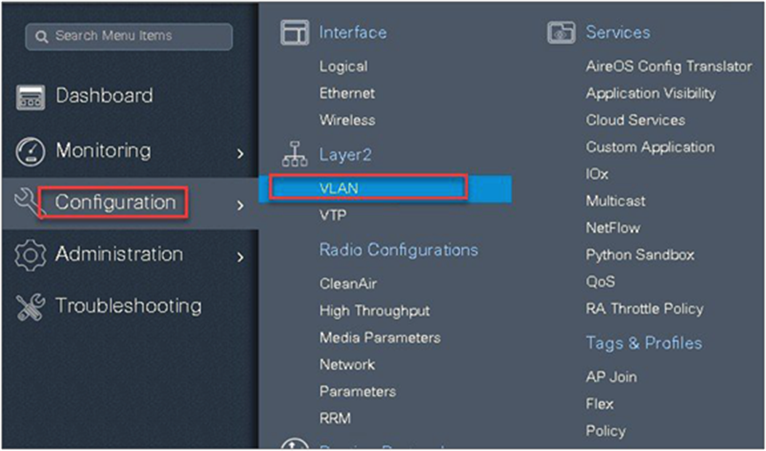
Navigate to Configuration > VLAN.
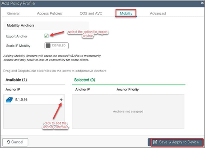
Step 8. An optional attribute to set is the export anchor configuration. Please refer to the mobility deployment guide to set up mobility peers.
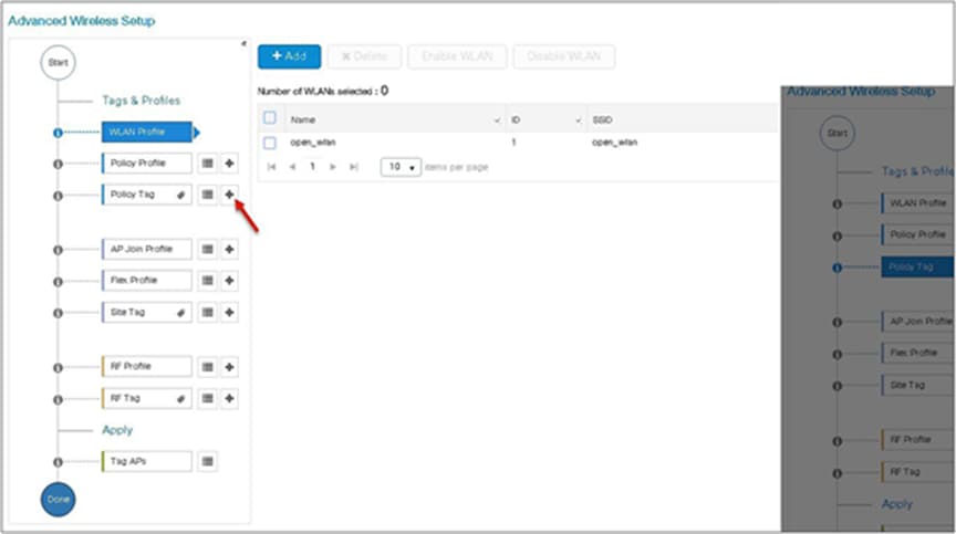
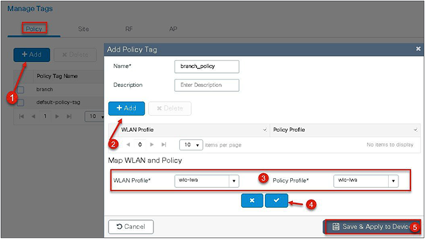
Step 9. Create a policy tag that binds the SSID and policy profile together.
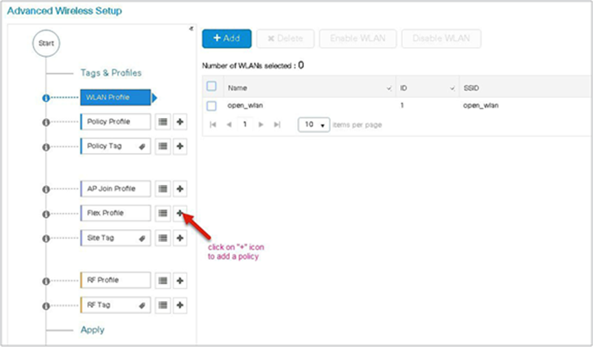
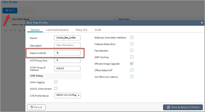
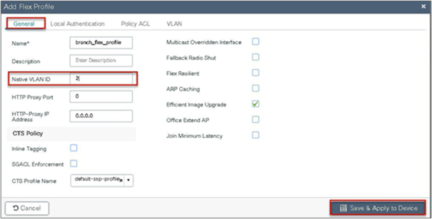
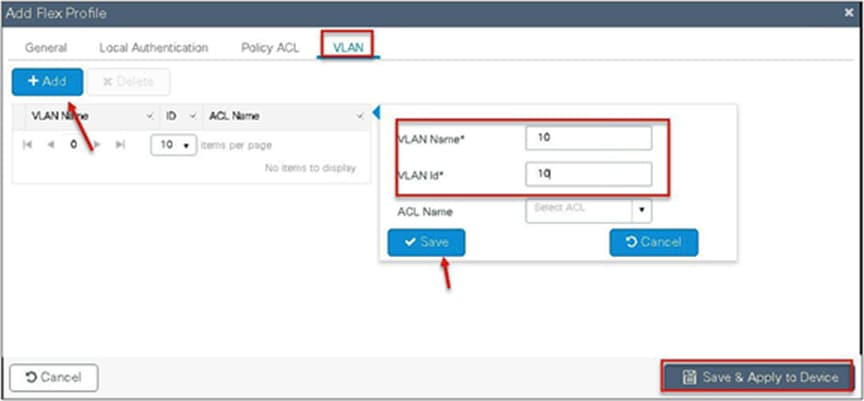
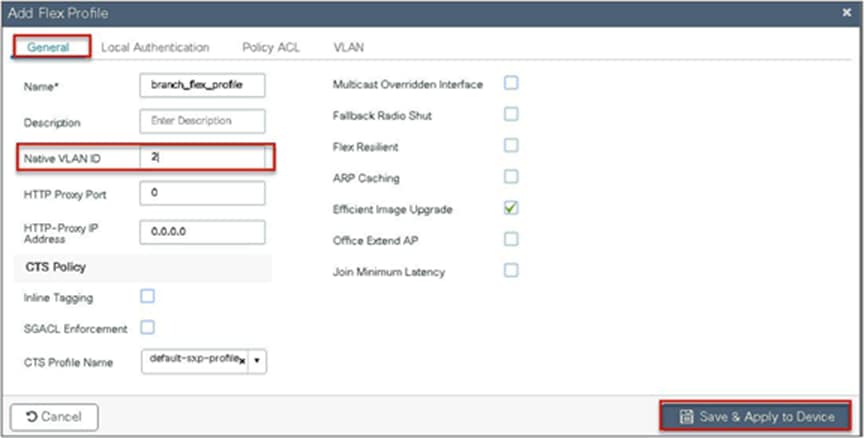
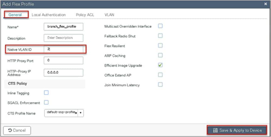
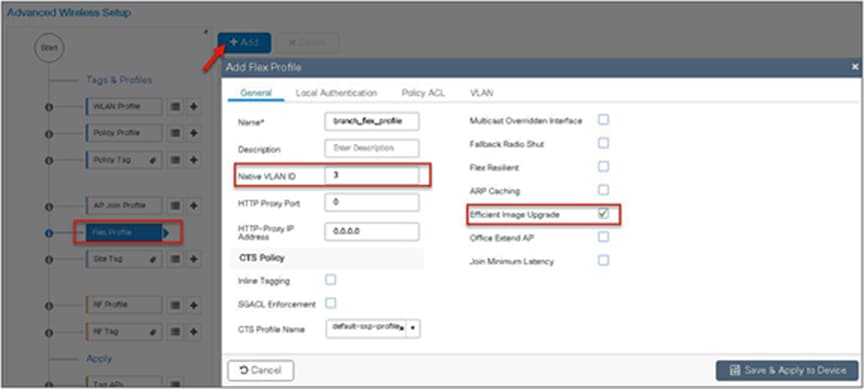
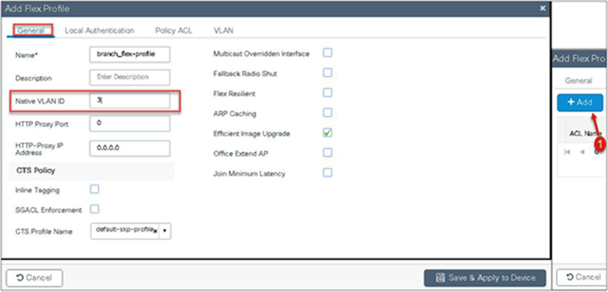
Step 10. Define a flex profile. The flex profile is used for configuring the VLANs on the AP that is used for the local switched SSIDs.
In this example, the guest SSID is centrally switched. In cases where there is a mix of central-switched and local-switched SSIDs, an administrator can create a flex profile and define the VLANs to be used by the local-switched SSIDs.
Step 11. Define the native VLAN for the FlexConnect APs.
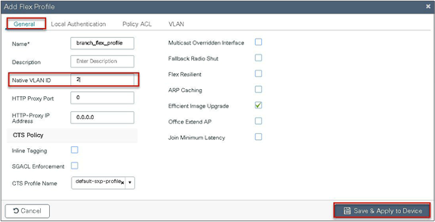
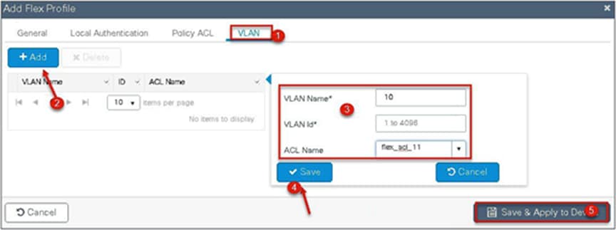
Step 12. Define the VLANS to be used for the local-switched SSID.

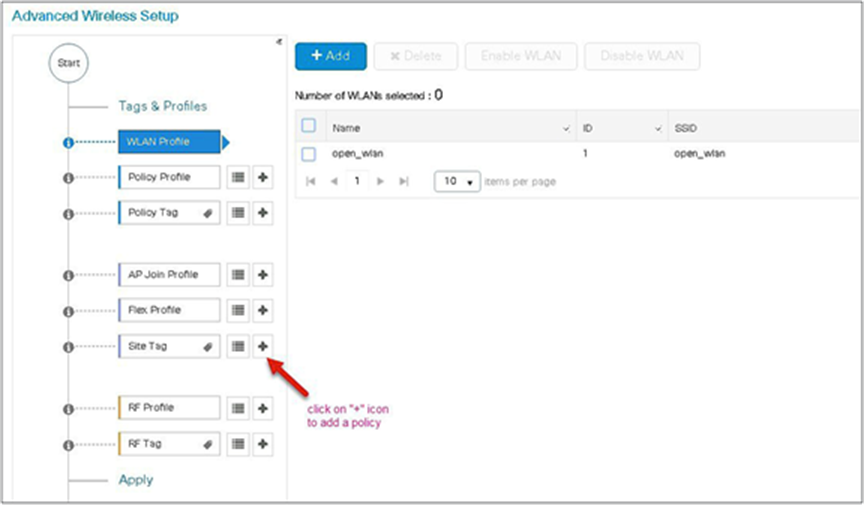
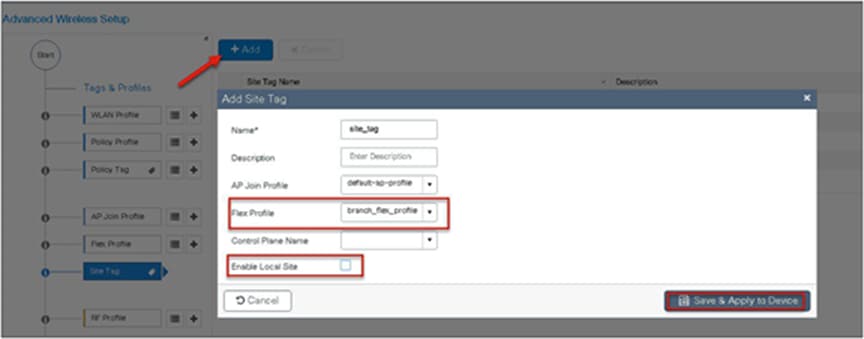
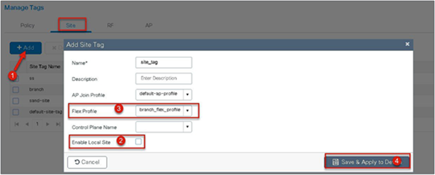
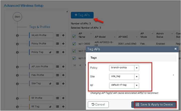
Step 13. Define a site tag that binds the flex profile and a default AP join profile. To add a flex profile on a site tag, uncheck the “Enable Local Site” option.
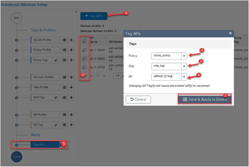
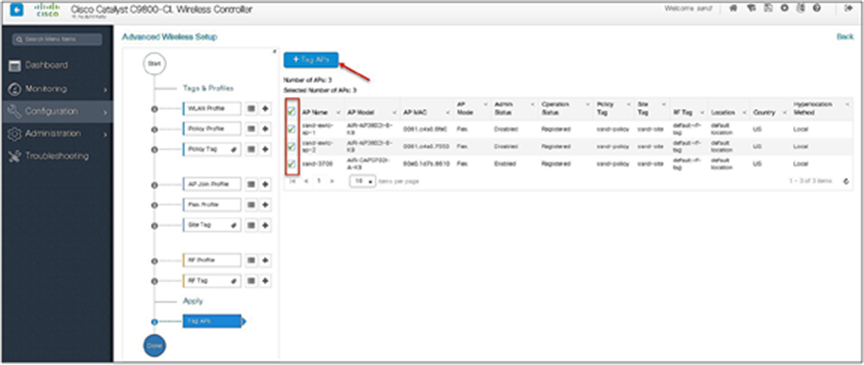
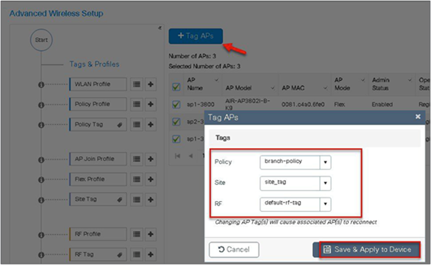
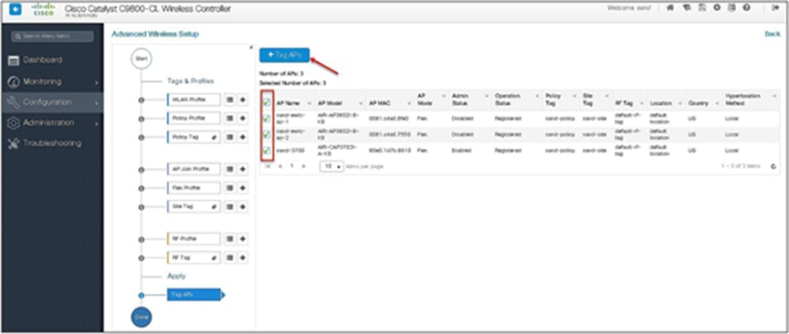
Step 14. The final stage is to provision the policy, site, and RF tag on the AP. Click on “Tag Aps” to select the profiles and have it configured for the AP. In this example, the AP is tagged using a default RF tag.
Once the AP is provisioned with the site tag, the AP gets converted to flex mode based on the site tag assigned to the AP.
If the AP is already in flex mode, there is no conversion. If the AP is in local mode, the AP would reboot to boot in FlexConnect mode.
The assigning of a tag does the auto-conversion of the AP mode based on properties of the tag.
The manual configuration for creating the SSID/tags and profiles is done using the WLC GUI. In this section, we will cover creating an enterprise SSID with dot1x enabled.
The first step in creating an enterprise SSID with dot1x is to define the AAA server for authentication.
Procedure
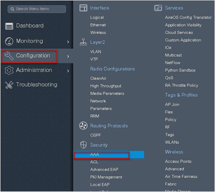
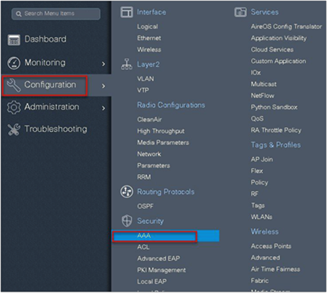
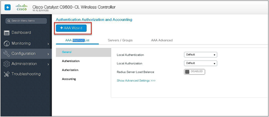
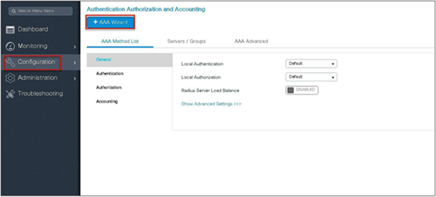
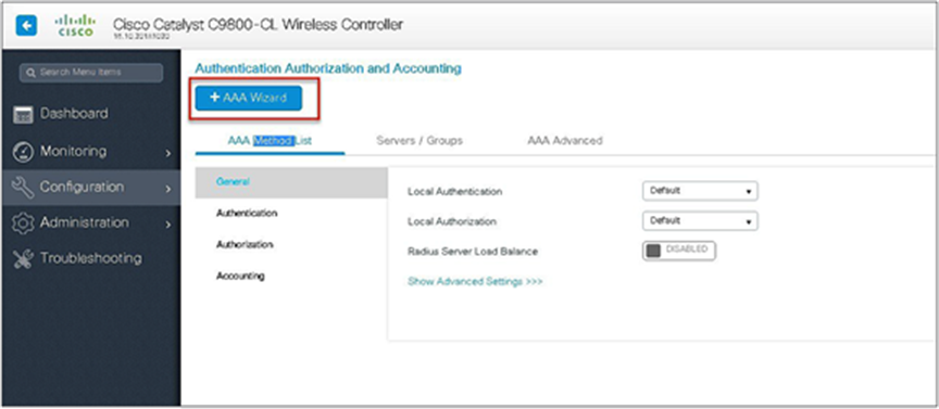
Step 1. Define an AAA server and method list for dot1x, which is mapped to the WLAN. The AAA server is created by navigating to the following:
Configuration > Security > AAA
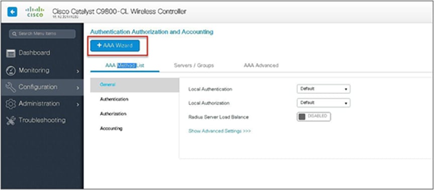
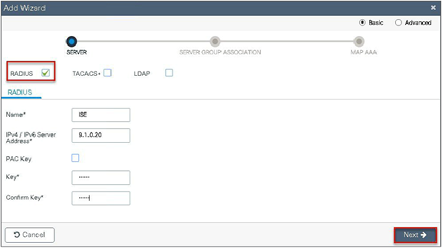
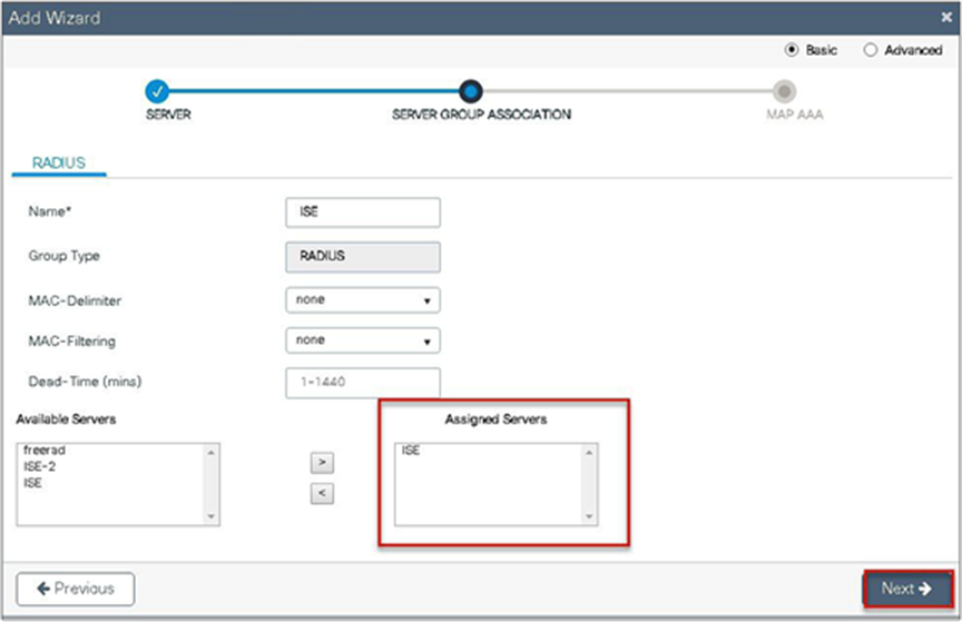
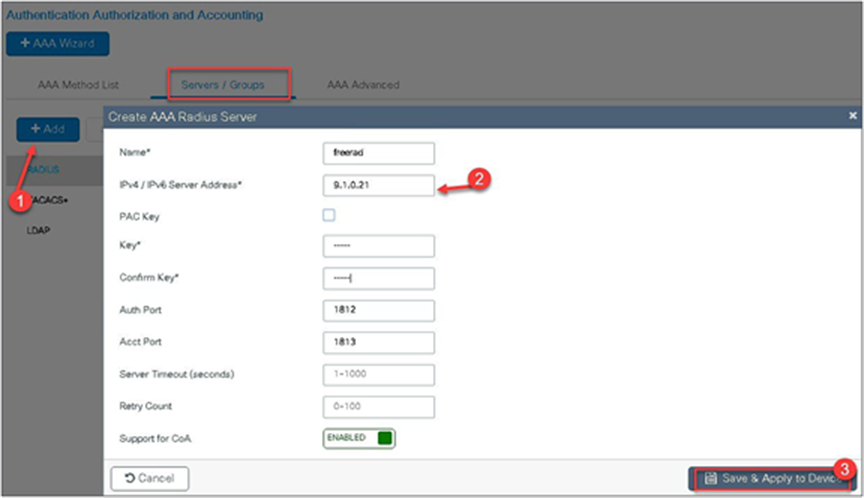
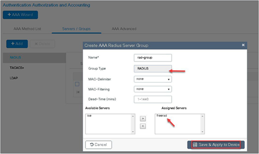
Step 2. Use the AAA wizard to create the server and server groups.
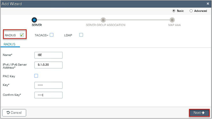
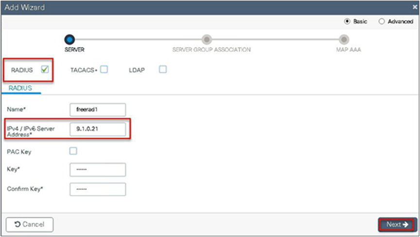
Step 3. Define a name for the server and specify the IP address and shared secret.
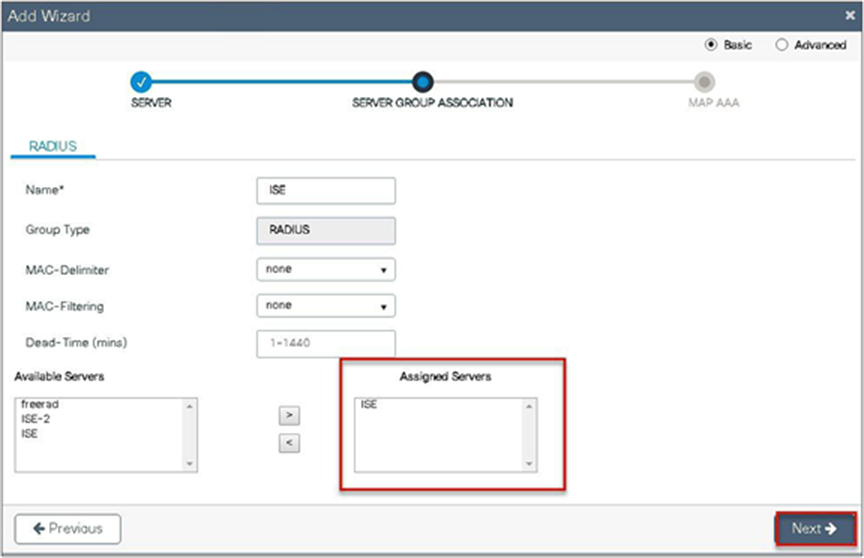
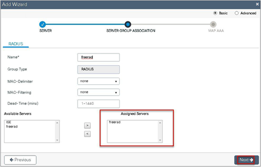
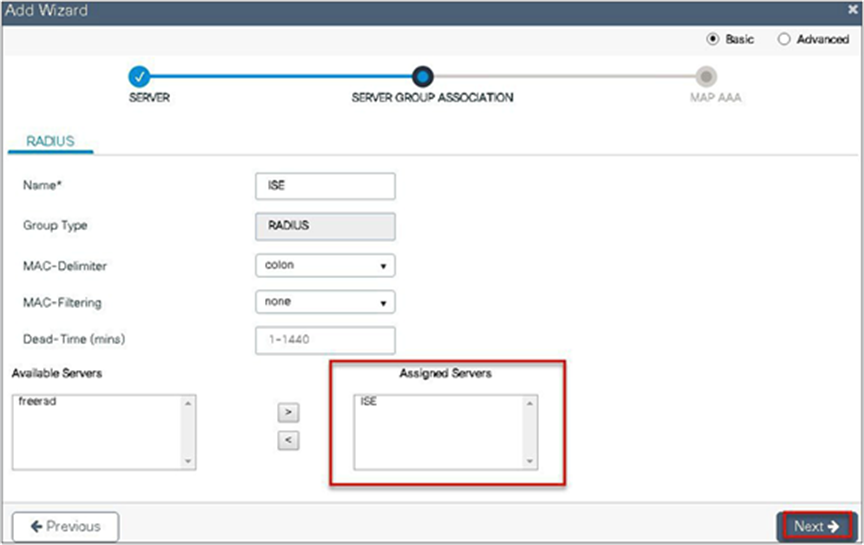
Step 4. Create a server group and map the server in the group.

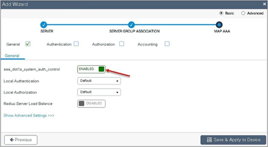
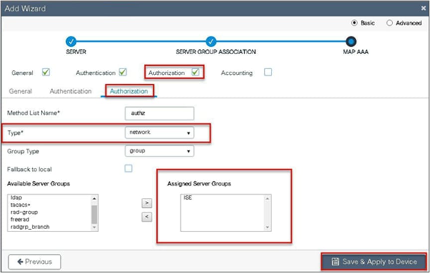
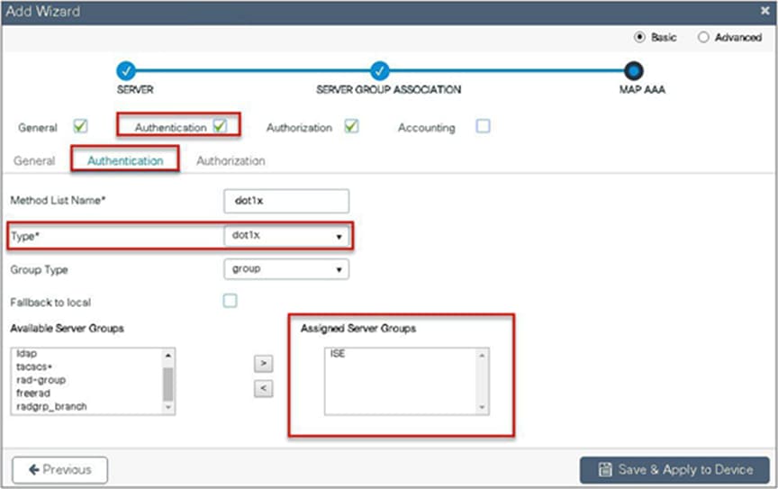
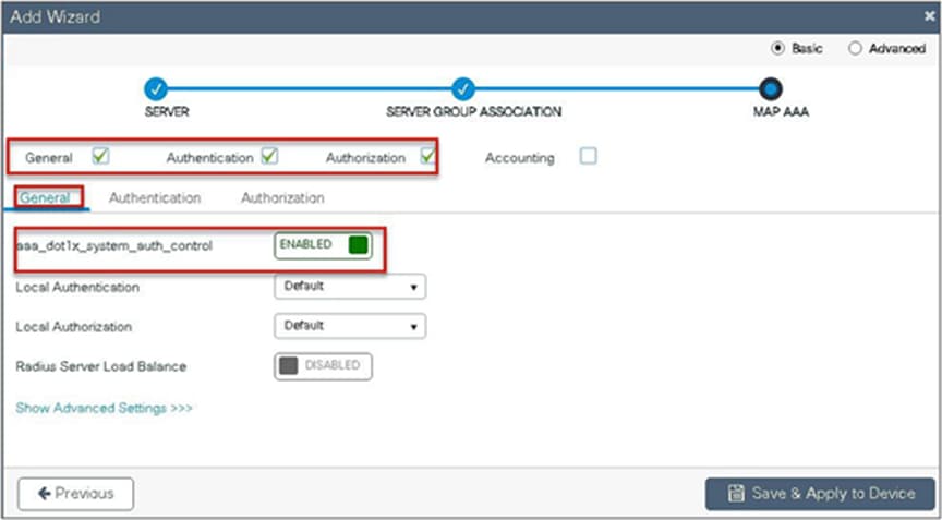
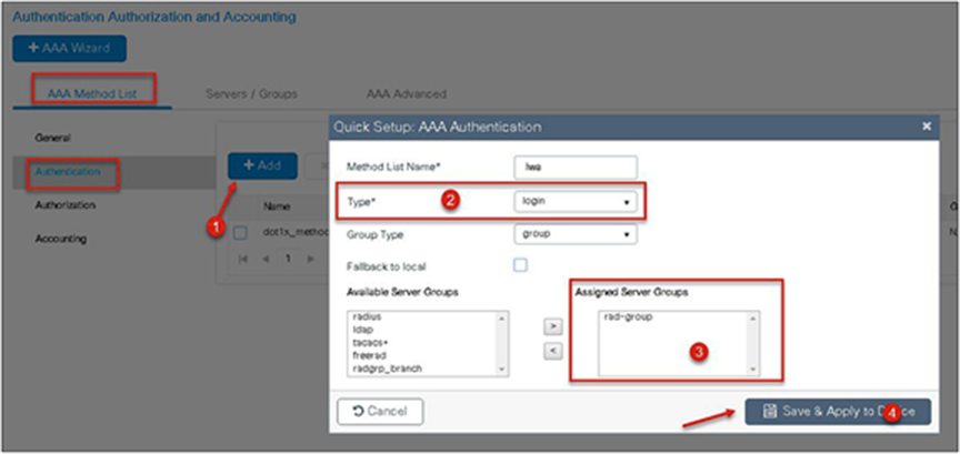
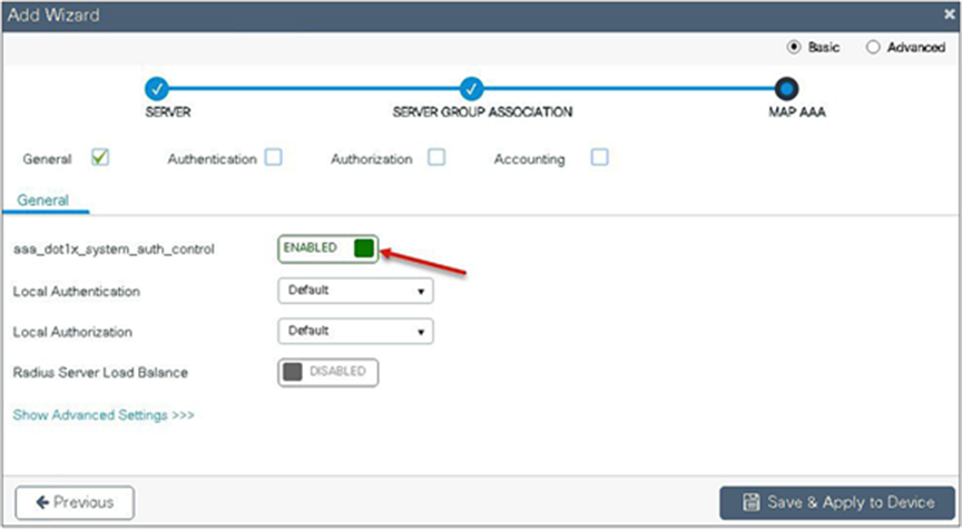
Step 5. Enable dot1x system control and checkmark the authentication and authorization profile.

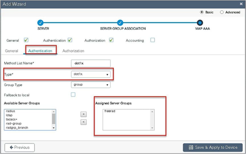
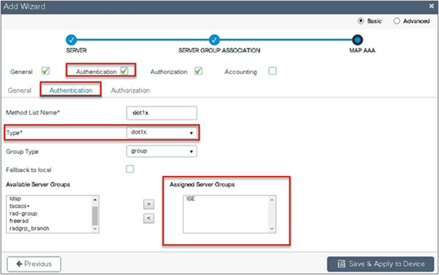
Step 6. Checkmark the authentication list and define the method type as dot1x and map the server group.

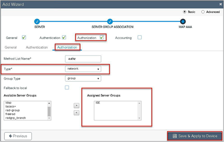
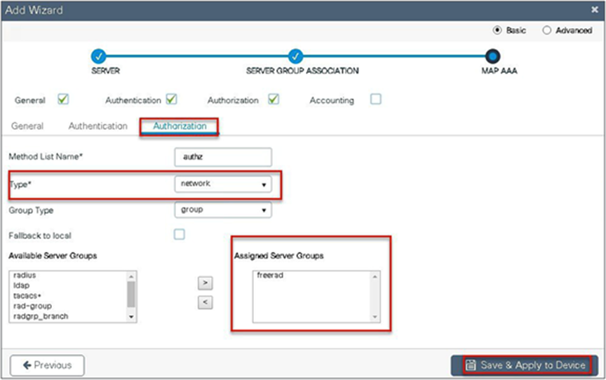
Step 7. Checkmark the authorization list, define the method type as network, and map the server group.
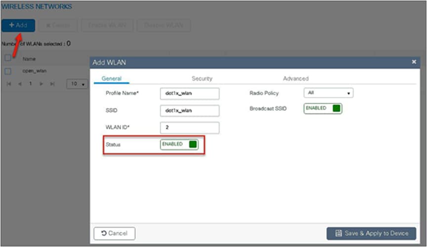
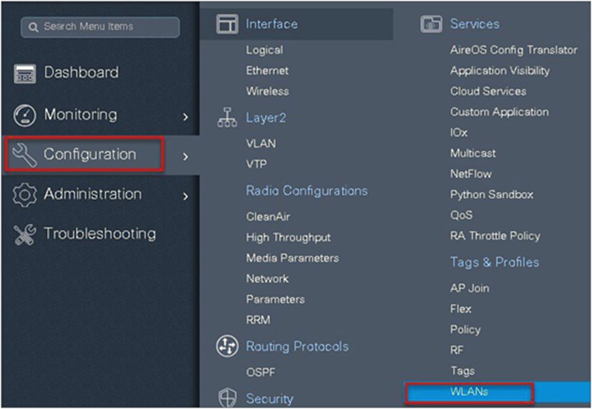
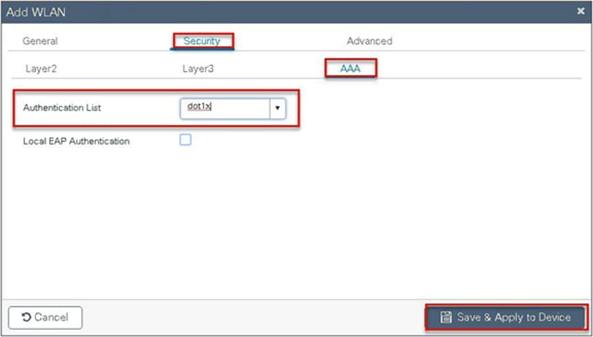
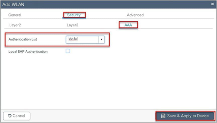
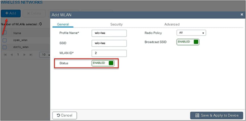
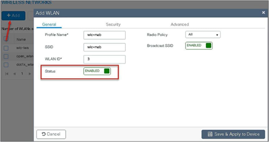
Step 8. Create a dot1x WLAN and map the method list on the WLAN.
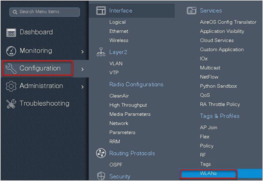
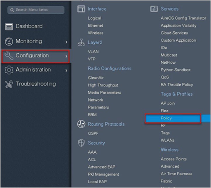
Navigate to Configuration > Tags & Profiles > WLAN to create the SSID.
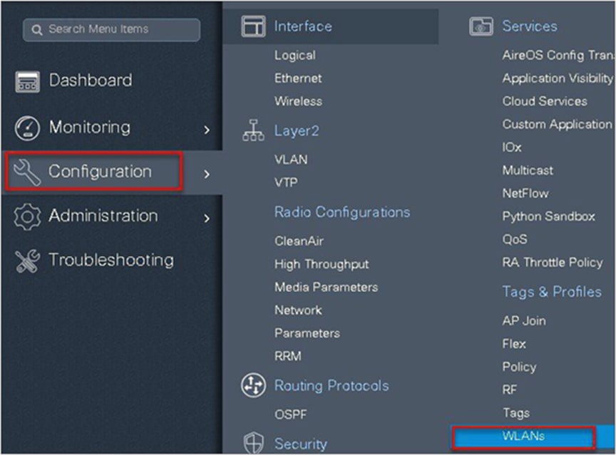

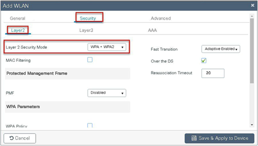
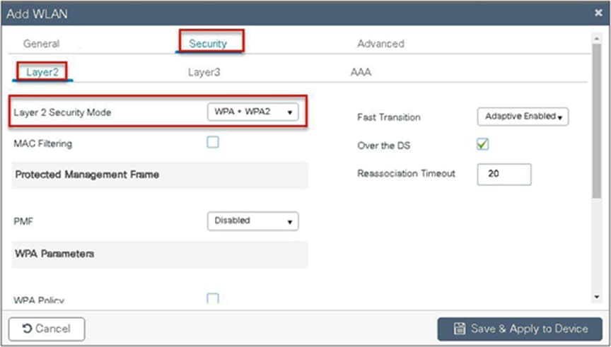
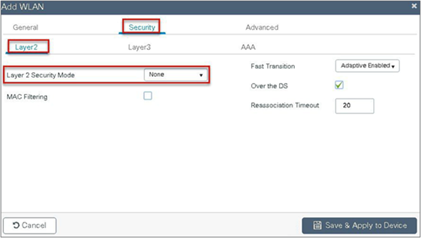
Step 9. Define the security for the WLAN.

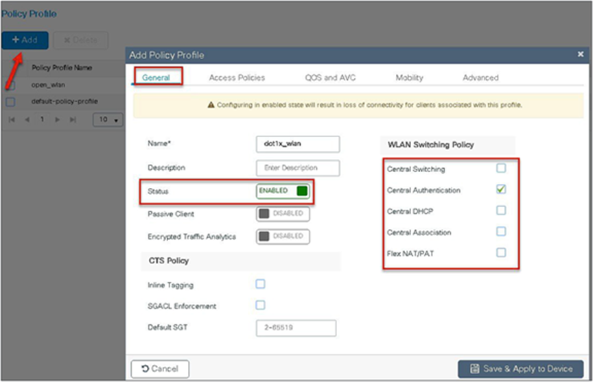
Step 10. Create a policy profile that defines the switching capability of the WLAN and the interface mapping to the WLAN.
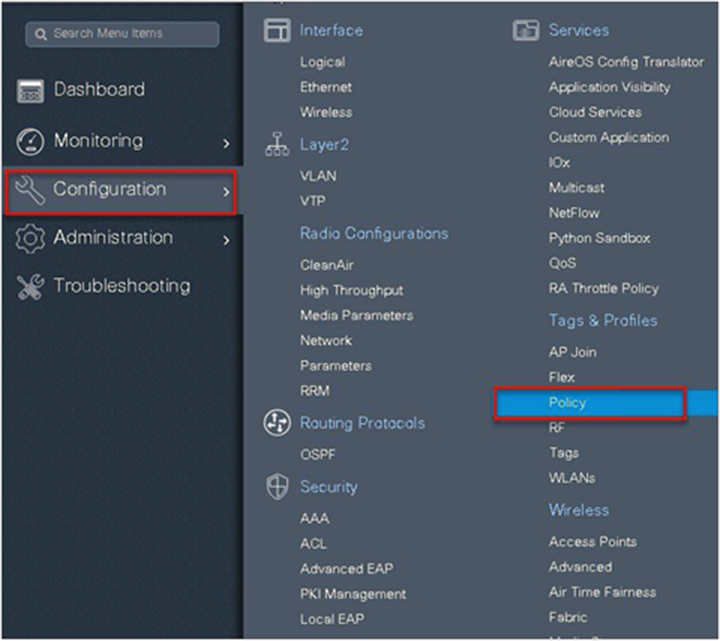

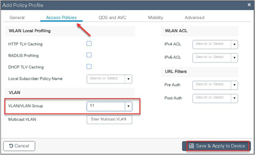
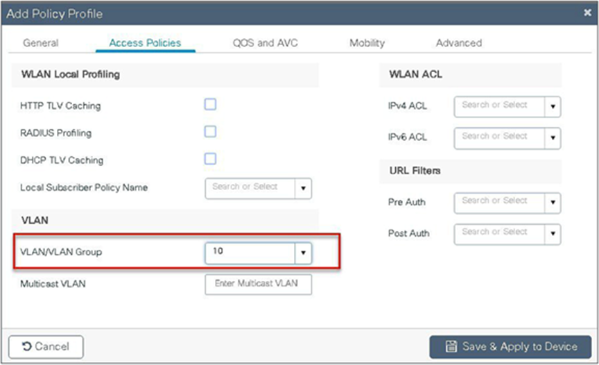
Step 11. Define the VLAN to be used by the SSID.

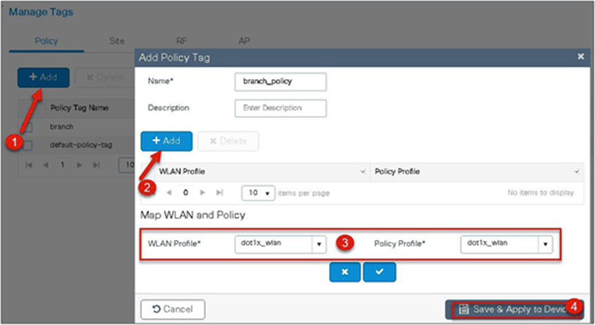
Step 12. Create a policy tag that bundles the policy profile and WLAN profile together.
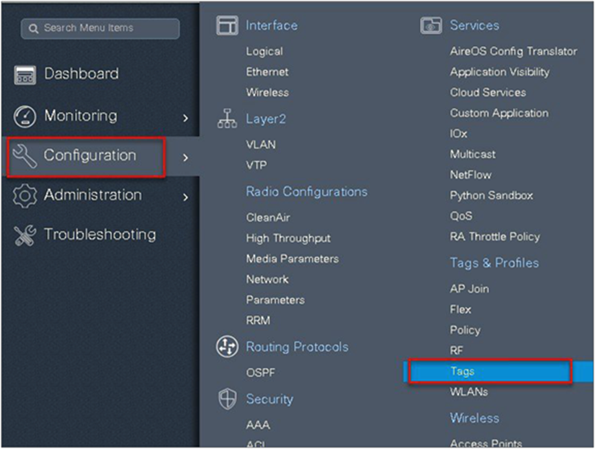
Navigate to Configuration > Tag and create a policy tag mapping the WLAN and policy profile.


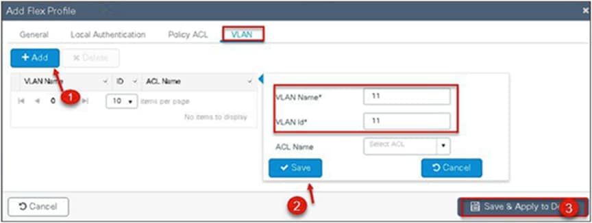
Step 13. Create a flex profile that defines the flex AP properties.
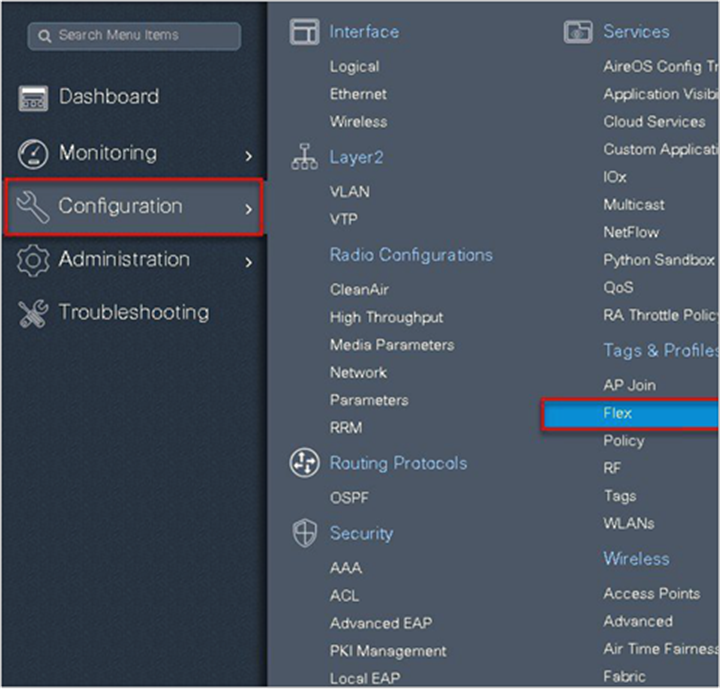
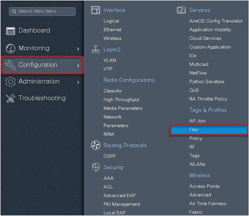
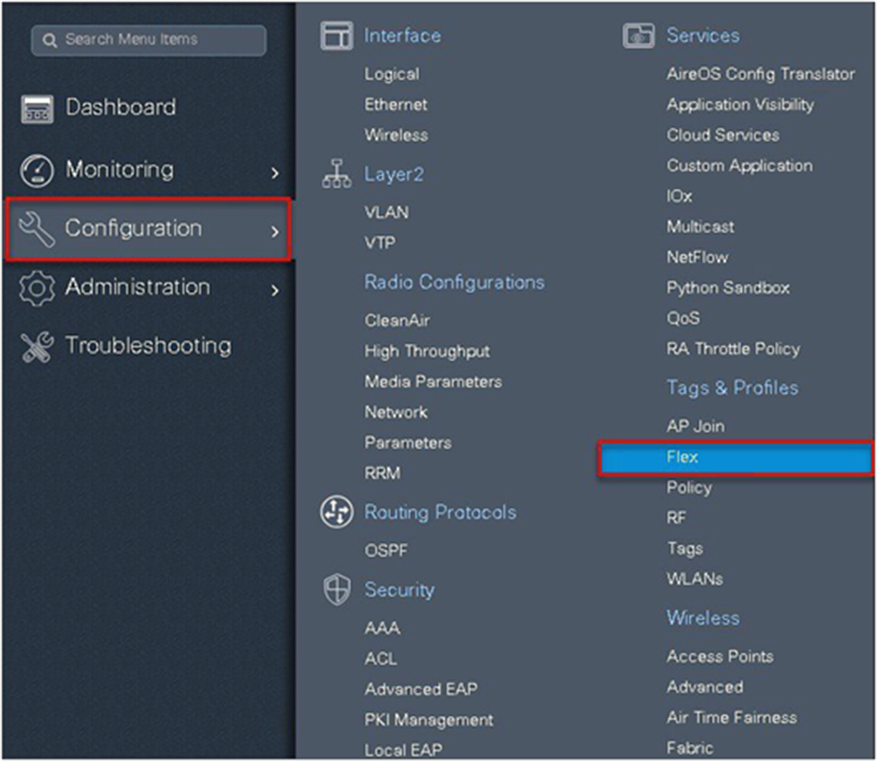
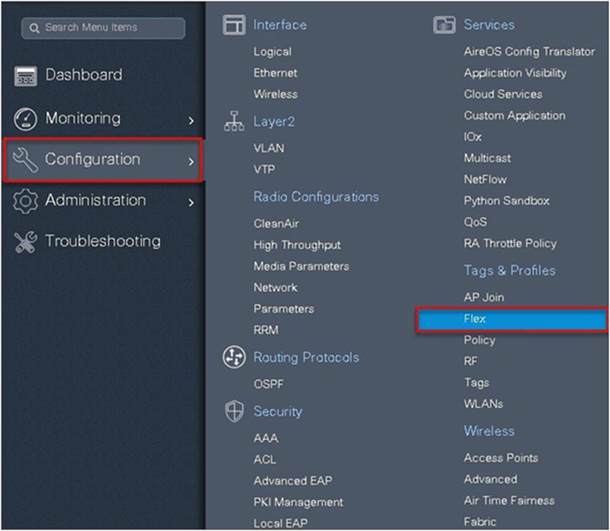
To create a flex profile, navigate to Configuration > Tags and Profile > Flex.
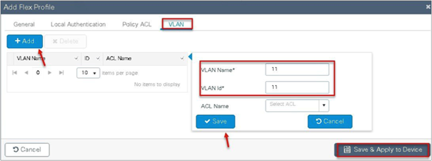
Step 14. Define the native VLAN for the FlexConnect AP.
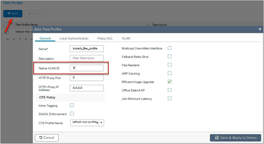
Step 15. Define the VLANS to be used for local-switched SSID. In this example, we use VLAN 11, which is the local-switched VLAN from the AP.

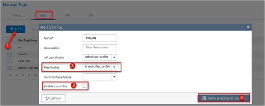
Step 16. Create a site tag that maps the flex and RF profile.
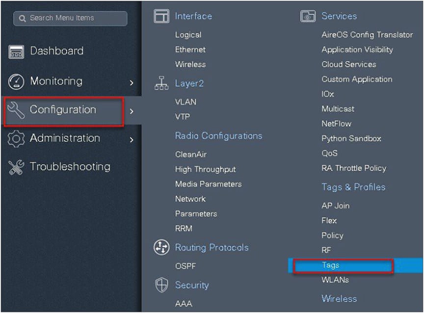
To create a site tag, navigate to Configuration > Tags and Profile > Tags.

Step 17. Uncheck “Enable Local Site” to map the flex profile on the site tag.
Step 18. Map the policy site tag and RF tag on the AP. To tag the AP, an administrator can use the following options.
● Use the advanced config wizard
● Use a static mapping
● Use a filter
Using the advanced config wizard to tag the APs:
Navigate to Configuration > Wireless Setup > Advanced.


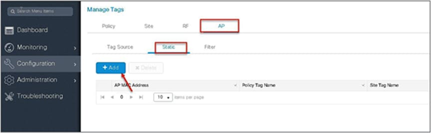
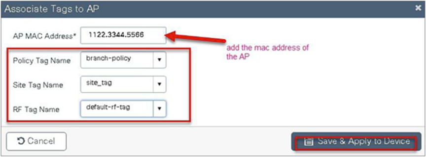
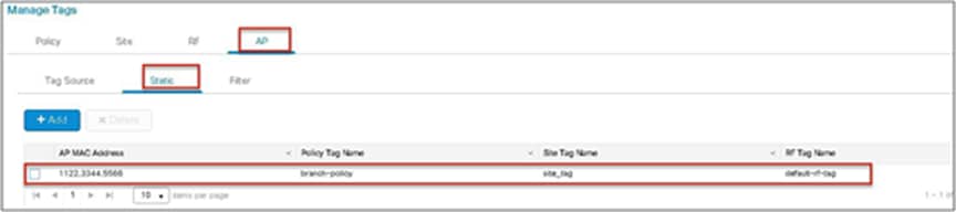
Using a static mapping to tag the APs.
Static mapping – In static mapping, the administrator needs to specify the MAC address of the AP along with the site, policy, and RF tag.
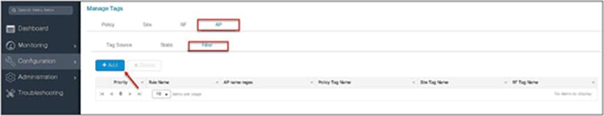
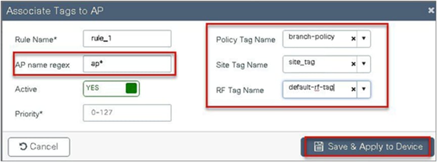
Using a filter to tag the AP:

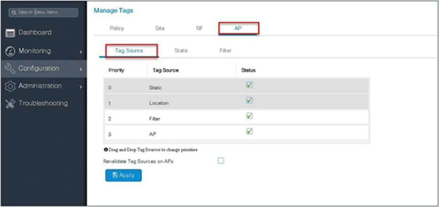
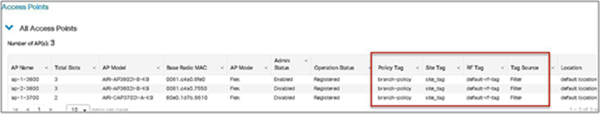
The access point summary page shows the source based on which tags were assigned to an AP.
Once the AP is provisioned with the site tag, the AP gets converted to flex mode based on the site tag assigned to the AP.
If the AP is already in flex mode, there is no conversion. If the AP is in local mode, AP will reboot to boot in FlexConnect mode.
The assigning of the tag does the auto-conversion of the AP mode based on the properties of the tag.
AAA override of VLAN on individual WLAN is supported for local switching. In order to have a dynamic VLAN assignment, the AP would have the VLAN pre-created based on a configuration using the flex profile mapped to the site tag. The VLANs used in the flex profile are pushed to the AP, and overriding of the WLAN is done using the VLAN the AP is programmed to.
◦ AAA VLAN override is supported on WLANs configured for local switching in central and local authentication modes.
● AAA override should be enabled on the policy profile mapped to the WLAN.
● The FlexConnect AP should have VLAN pre-created from WLC. This is done in the flex profile mapped to the site tag.
● If VLANs returned by the AAA override are not present on the AP, the client will be excluded and not allowed access to the network.
● Multicast traffic on an AAA-overridden VLAN is not supported.
The procedure to enable VLAN override is outlined below along with the GUI configuration. The WLAN here is enabled for dot1x-based authentication.
Procedure
Step 1. Define an AAA server and method list for dot1x, which is mapped to the WLAN. The AAA server is created by navigating to the following:
Configuration > Security > AAA
Step 2. Use the AAA wizard to create the server and server groups.

Step 3. Define a name for the server and specify the IP address and shared secret.
Step 4. Create a server group and map the server in the group.
Step 5. Enable dot1x system control and checkmark the authentication and authorization profile.
Step 6. Define the method type as dot1x and map the server group.

Step 7. Define the method type as network and map the server group.
Step 8. Create a dot1x WLAN and map the method list on the WLAN.
Navigate to Configuration > Tags & Profiles > WLAN to create the SSID.

Step 9. Create a flex profile. Create a VLAN on the flex profile, which is the VLAN returned by the AAA.

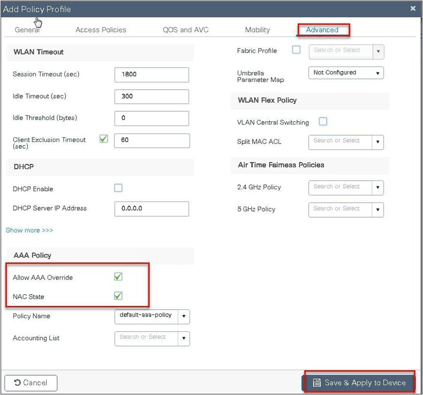
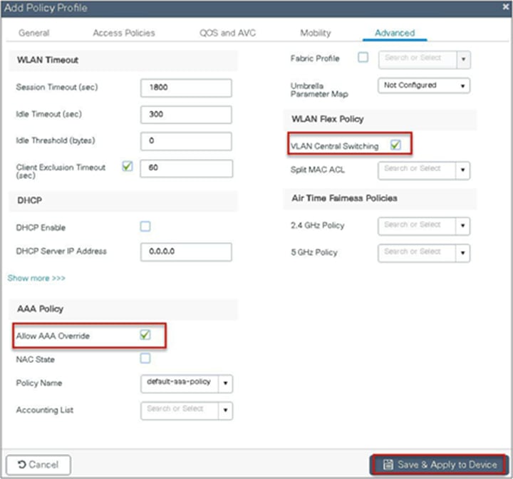
Step 10. Create a policy profile, enable local switching and central authentication on the profile, map the default VLAN for the WLAN, and enable AAA override.


Step 11. Map the WLAN to the policy profile.
Navigate to Configuration > Tags and create a policy tag mapping the WLAN and policy profile.
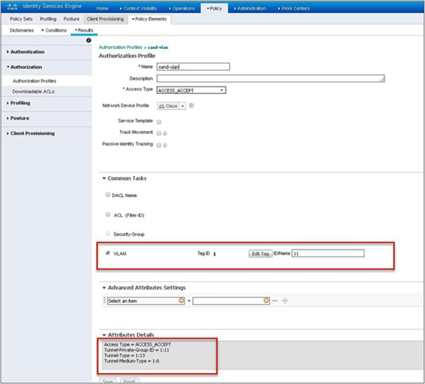
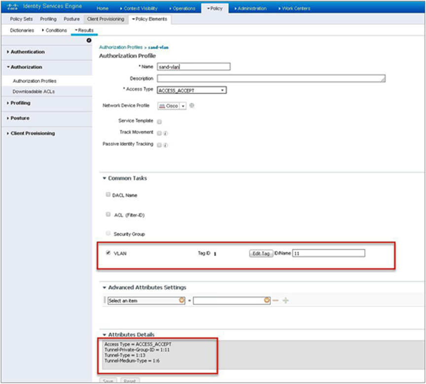
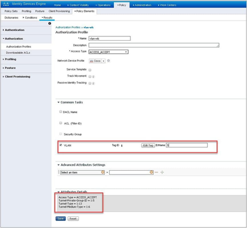
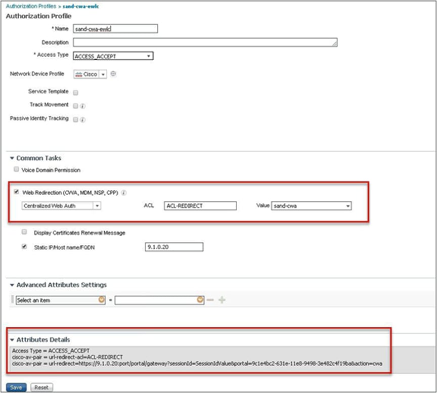
Step 12. Create an authorization profile on the ISE to override the VLAN from AAA.
Create the respective authorization rules to return the authorization profile as part of access accept.
The screenshot below is for the authorization profile. The authorization rules should refer to the profile created.
Step 13. Create a site tag and map the flex profile on the site tag.

Step 14. Map the policy site tag and RF tag on the AP using the advanced config wizard.
Navigate to Configuration > Wireless Setup > Advanced.


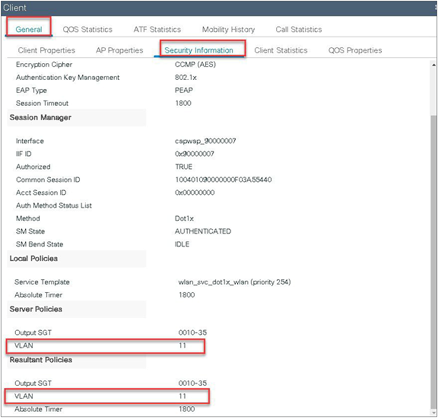
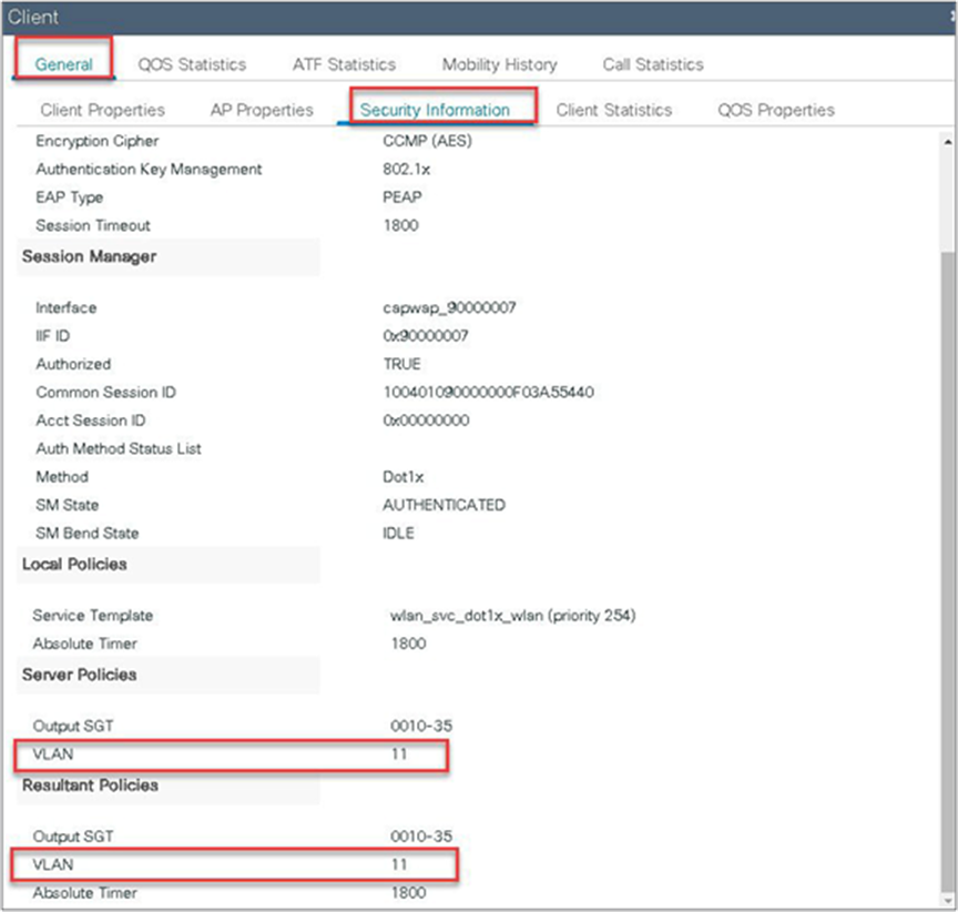
Step 15. Associate a client on the WLAN and authenticate using the username configured in the AAA server in order to return the AAA VLAN as the attribute.
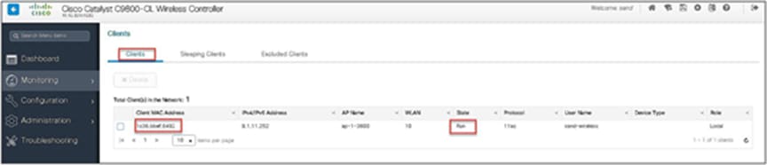
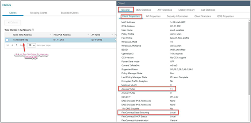
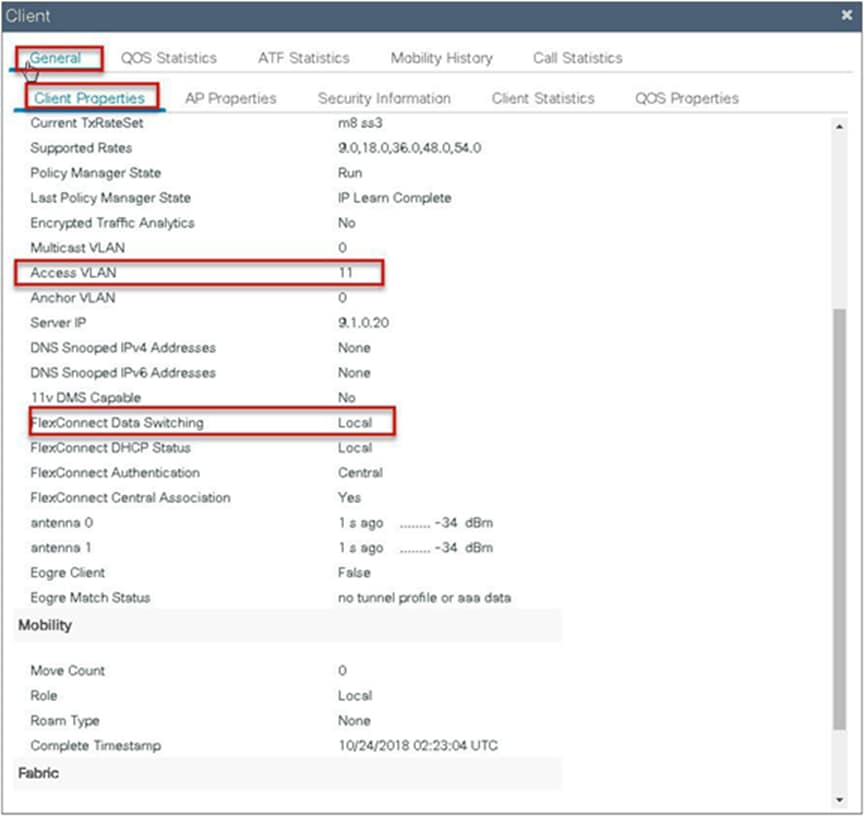
Verify the client connectivity by navigating to monitoring wireless clients and verify the access VLAN that the client is mapped to.
Double-click on the client MAC to open up the details of the client session.
FlexConnect VLAN-based central switching
VLAN-based central switching is a feature that will enable central or local switching based on the VLAN returned as part of the AAA override. If the VLAN provided by the AAA is part of the VLAN present on the AP, the client would be locally switched, and if the VLAN returned by the AAA is not present in the AP and is available at the WLC, the client would be centrally switched.
Traffic flow on WLANs configured for local switching when flex APs are in connected mode:
● If the VLAN is returned as one of the AAA attributes and that VLAN is not present in the flex AP database, traffic will switch centrally and the client will be assigned this VLAN/interface returned from the AAA server provided that the VLAN exists on the WLC.
● If the VLAN is returned as one of the AAA attributes and that VLAN is not present in the flex AP database, traffic will switch centrally. If that VLAN is also not present on the WLC, the client will be excluded with the reason being VLAN failure.
● If the VLAN is returned as one of the AAA attributes and that VLAN is present in the FlexConnect AP database, traffic will switch locally.
● If the VLAN is not returned from the AAA server, the client will be assigned a VLAN mapped on the policy profile that is attached to the policy tag on that FlexConnect AP and traffic will switch locally.
● If the VLAN returned as part of the AAA attribute is present on both the AP and WLC, the client will be locally switched. The VLAN on the AP takes precedence over the one on the WLC.
Traffic flow on WLANs configured for local switching when flex APs are in standalone mode:
● If the VLAN returned by an AAA server is not present in the flex AP database, the client will be put to default VLAN (that is the VLAN mapped on the policy profile, which is linked to the WLAN). When the AP connects back, this client will be de-authenticated and will switch traffic centrally.
● If the VLAN returned by an AAA server is present in the flex AP database, the client will be put into a returned VLAN, and traffic will switch locally.
● If the VLAN is not returned from an AAA server, the client will be assigned a WLAN mapped VLAN on that FlexConnect AP, and traffic will switch locally.
Steps to configure FlexConnect VLAN-based central switching
Procedure
Step 1. Define an AAA server and method list for dot1x, which is mapped to the WLAN. The AAA server is created by navigating to the following:
Configuration > Security > AAA.
Step 2. Use the AAA wizard to create the server and server groups.
Step 3. Define a name for the server and specify the IP address and shared secret.

Step 4. Create a server group and map the server in the group.
Step 5. Enable dot1x system control and checkmark the authentication and authorization profile.

Step 6. Define the method type as dot1x and map the server group.
Step 7. Define the method type as network and map the server group.

Step 8. Create a dot1x WLAN and map the method list on the WLAN.
To create an SSID, navigate to Configuration > Tags & Profiles > WLANs.


Step 9. Create a policy profile, enable local switching and central authentication on the profile, map the default VLAN for the WLAN, and enable AAA override.


Step 10. Map the WLAN to the policy profile.
Navigate to Configuration > Tag and create a policy tag mapping the WLAN and policy profile.

Step 11. Create a flex profile and define a VLAN on the flex profile returned by the AAA radius server.

Step 12. Create an authorization profile on the ISE to override the VLAN.
Create the respective authorization rules to return the authorization profile as part of access accept.
Step 13. Create a site tag and map the flex profile on the site tag.

Step 14. Map the policy site tag and RF tag on the AP using the advanced config wizard.
Assigning a site tag on an AP would result in AP reboot due to conversion to FlexConnect mode. The reboot is avoided if the AP is already in FlexConnect mode.
Navigate to Configuration > Wireless Setup > Advanced.


Step 15. Associate a client on the WLAN and authenticate using the username configured in the AAA server in order to return the AAA VLAN as an attribute.
Verify the client connectivity by navigating to Monitoring > Wireless > Clients and verify the access VLAN the client is mapped to.
In this step, the AAA returns VLAN 11, which is present in the AP database results in the local-switched WLAN. Double-click on the client MAC to open the details of the client session.
Step 16. Create an authorization profile to return a VLAN that is not present on the AP database but on the WLC.
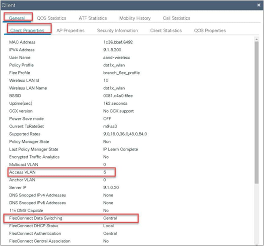
In this example, VLAN 5 is present on the WLC and not on the AP database, which results in the WLAN being central switched.
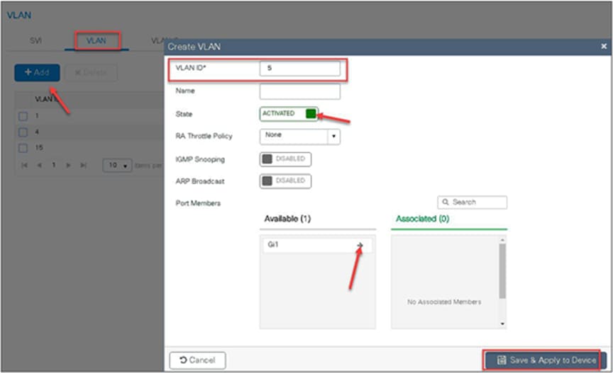
Step 17. Validation on the presence of VLAN 5 on the WLC.
Navigate to Configuration > VLAN.
Step 18. Associate a client on the WLAN and authenticate using the username configured in the AAA server in order to return the AAA VLAN (VLAN5) as the return attribute.
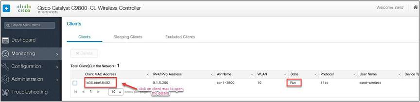
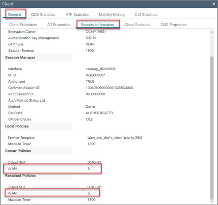
Verify the client connectivity by navigating to Monitoring > Wireless > Clients and verify the access VLAN the client is mapped to and the switching properties for the client.
Double-click on the client MAC to open the details of the client session.
Local authentication and backup radius server
In most typical branch deployments, it is easy to foresee that client 802.1X authentication takes place centrally at the WLC located at the data center; however, there arises certain concerns with central authentication at the WLC.
How can wireless clients perform 802.1X authentication and access data center services if the WLC fails?
How can wireless clients perform 802.1X authentication if the WAN link between the branch and data center fails? Is there any impact on branch mobility during WAN failures?
Does the FlexConnect solution provide no operational branch downtime?
FlexConnect local authentication and backup/local radius can address the above concerns by enabling the branch to operate independently in case of a WAN outage or connectivity issue with the controller.
● The use of local authentication in branch enables resiliency at the branch location by providing wireless access in scenarios where the WAN connectivity is lost with the data center. The AP moves to standalone mode and provides wireless access with authentication for dot1x directed to a radius server available at the branch side.
● The AP can act as a radius server, and this feature is only supported on the Wave 1 APs.
● This feature can be used with central authentication or local authentication. In the central authentication case, the WLC will authenticate the wireless clients as long as the AP is in connected mode.
● Once the AP loses connectivity with the WLC, the AP will move to standalone and authenticate the client locally.
● This feature can be used with local authentication and local switching. In cases where there is a local radius server at the branch, the AP can forward the radius request to the radius server at the branch, thereby avoiding the latency variation caused by the WAN links.
● EAP-LEAP is the only method supported for AP as radius server.
Local authentication with external radius server
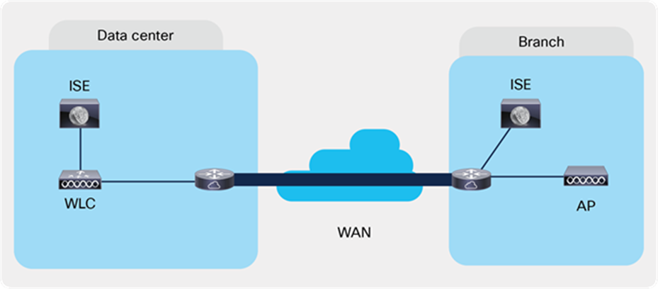
Local Authentication with External RADIUS server at the Branch
Steps for local authentication and backup radius server
Procedure
Step 1. Define an AAA server. For branch deployment, specify the AAA server used at the branch side.
Navigate to Configuration > Security > AAA and start the AAA wizard.
The wizard helps in creating the following flow.
● Create a radius server.
● Create a server group and map the radius server on the server group.
● Map the server for dot1x authentication.
Step 2. Create an SSID on the controller for dot1x authentication.
To create an SSID, navigate to Configuration > Tags & Profiles > WLANs.
Defines the method list created for dot1x on the WLAN AAA settings.


Step 3. Create a policy profile and enable local switching and central authentication on the profile.
Step 4. Map the default VLAN for the WLAN.
Step 5. Map the WLAN to policy profile.
Navigate to Configuration > Tag and create a policy tag mapping the WLAN and policy profile.
Step 6. Create a flex profile to create the VLAN on the profile to be used by the SSID.


Step 7. Create a site tag and map the flex profile on the site tag.
Uncheck “Enable Local Site” to add the flex profile on the site tag.

Step 8. Map the policy profile and site tag on the AP. To tag the AP, open the advanced config wizard and tag the AP with corresponding tags.
The mapping can be provisioned by creating a filter list based on the AP name.
Assigning a site tag on an AP might result in AP reboot due to conversion to FlexConnect mode.
The reboot is avoided if the AP is already in FlexConnect mode.
Navigate to Configuration > Wireless Setup > Advanced.


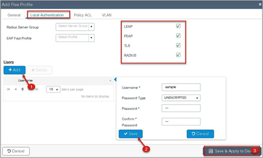
FlexConnect AP can be configured as a RADIUS server for LEAP client authentication. In standalone mode and also when local authentication feature is enabled on the WLANs, FlexConnect AP will perform dot1x authentication on the AP itself using the local radius facility.
To have the FlexConnect AP configured as the radius server, repeat steps 2, 3, 4, 5, 7, and 8 in the procedure section of configuring local authentication with external radius server.
The flex profile needs to be reconfigured to enable local radius server functionality.
Procedure
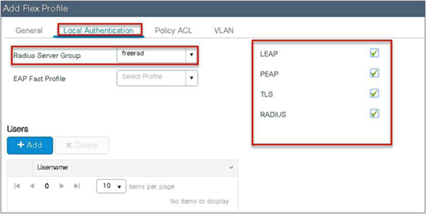
Step 1. Create a flex profile. Navigate to Configuration > Flex.
Step 2. Specify the native VLAN ID for the AP. On the local authentication, specify the EAP methods to be used.
Add local users for authentication on the AP. The local users reside on the AP.
CCKM/OKC and PMK caching enables fast roaming for wireless clients. Fast roaming is achieved by caching a derivative of the primary key from a full EAP authentication so that a simple and secure key exchange can occur when a wireless client roams to a different access point. This feature prevents the need to perform a full RADIUS EAP authentication as the client roams from one access point to another.
The controller supports CCKM/OKC and PMK caching, and the controller takes care of distributing the primary key to the APs. The controller distributes the primary key to all the APs whose site tag and policy tag are the same. This results in the ability to do fast roaming across the AP within the same site. The distribution of the primary key is done based on the site tag of the AP site the client initially associates, and the controller now finds all the APs that have a similar site tag and policy tag and pushes the primary key on those APs, thus enabling fast roaming among the APs.
● The AP in standalone mode can support a maximum of two radius servers. The first server added in the server group acts as the primary. The second radius server acts as a backup for the primary.
● The AP as radius server is supported only on Wave 1 APs. On 16.10, the EAP method supported for the AP as the radius server is EAP-LEAP.
● Fast roaming is not supported with the default site tag. If the APs are mapped to a default site tag, the primary key for caching is not shared among those APs.
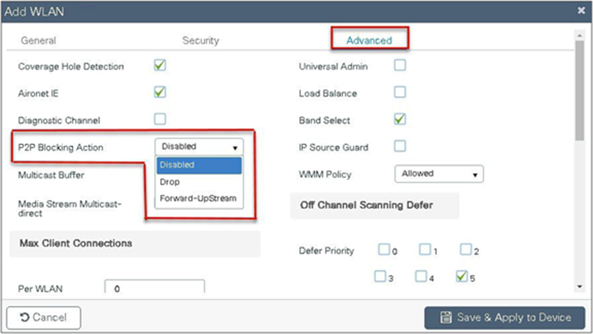
The controller supports peer-to-peer blocking in local switching mode. The configuration for the peer-to-peer blocking is available while creating the WLAN.
Peer-to-peer blocking can be configured with any of the following three actions.
● Disabled – Disables peer-to-peer blocking and bridged traffic locally within the controller for clients in the same subnet. This is the default value.
● Drop – Causes the controller to discard packets for clients in the same subnet.
● Forward upstream – Causes the packet to be forwarded on the upstream VLAN. The devices above the controller decide what action to take regarding the packet.
Summary
● Peer-to-peer blocking is configured per WLAN.
● Per WLAN, peer-to-peer blocking configuration is pushed by the WLC to FlexConnect APs.
● Peer-to-peer blocking action configured as drop or forward-upstream on WLAN is treated as peer-to-peer blocking enabled on the FlexConnect AP.
Procedure
Refer to the steps defined in the advanced config wizard of this document to create an SSID, policies, and tags on the controller.
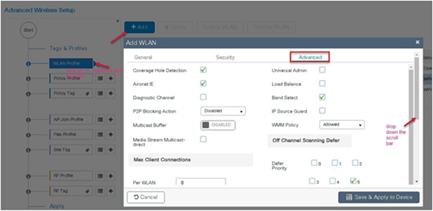
Advanced wireless setup wizard
Select the peer-to-peer blocking action in the advanced tab of the WLAN creation to have the feature configured.
Once the P2P blocking action is configured on the WLAN, it is pushed from the WLC to the FlexConnect APs. The config will be retained by the AP when it moves from connected mode to standalone mode.
ACL usage on FlexConnect deployment provides a way to cater the need to provide access control at the FlexConnect AP for protection and integrity of locally switched data traffic from the AP. FlexConnect ACLs are created on the WLC and should then be configured with the VLAN on a flex profile that is mapped to a site tag. The site tag gets assigned to an AP. The ACL name can also be returned as part of an attribute from AAA.
The ACL implementation for branch deployments can be done through the following methods:
● WLAN ACL - The ACL is applied on the WLAN dot11 interface and is enforced to all the clients connecting on that SSID.
● WLAN ACL - The ACL is applied on the WLAN dot11 interface and is enforced to all the clients connecting on that SSID.
● Client ACL- The ACL is returned as part of the AAA attribute and is enforced for the specific client.
The ACL for the enforcement needs to be created on the WLC and also needs to be pushed to the Flex AP. The way to push the ACL to the flex AP is using the flex profiles. An administrator can create a policy ACL on the flex profile to push the ACL on the AP or use a dummy VLAN to ACL mapping on the flex profile. When a wireless client joins an SSID and an ACL is enforced either through WLAN/VLAN or AAA, the WLC checks if the ACL is also pushed to the AP. If the ACL is not present on the AP, the client is moved to the exclusion list.
Procedure for WLAN ACL
Procedure for WLAN ACL:
● Create an ACL on the controller.
● Apply the ACL on the respective policy profile for the WLAN.
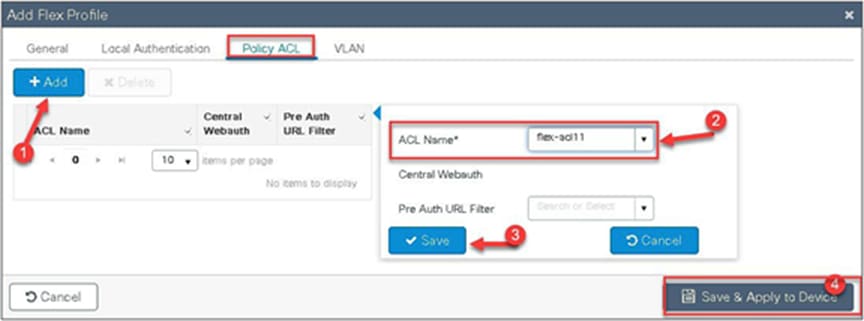
● Now create a flex profile, add a policy ACL, and map the corresponding ACL on the flex profile.
● Also add the ACL as part of the policy profile.
● Connect the client and validate that the ACL works.
Procedure
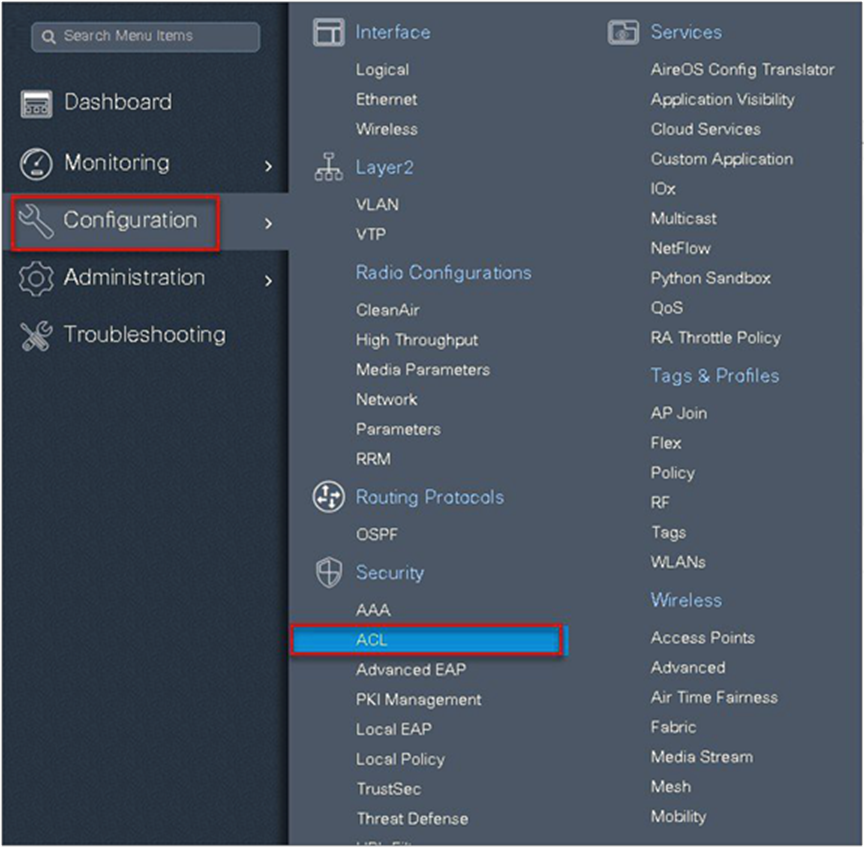
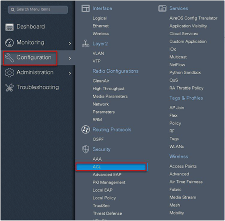
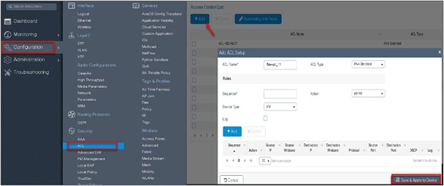
Step 1. Create an ACL on the WLC by navigating to Configuration > Security > ACL.
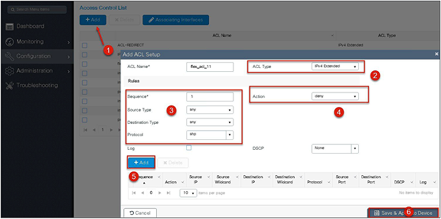
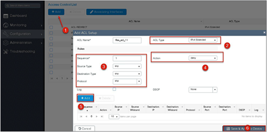
Step 2. Perform the following steps:
● Click on “Add” to create an ACL, and define an ACL name.
● Specify the type of ACL: standard or extended.
● Define the rules for the ACL.
● Specify the action as permit or deny.
● Add the ACL rules and save the ACL.
Step 3. Refer to the steps in the procedure of the advanced configuration wizard for the following:
● Create a WLAN
● Creation of policy profile (refer to the screenshot below to add the ACL)
● Policy tag mapping
● Flex profile (refer to the screenshot below to map the ACL using the policy ACL)
● Creation of the site tag
● Tagging the AP
Advanced wireless setup wizard:
The ACL is attached to the WLAN through the policy profile.
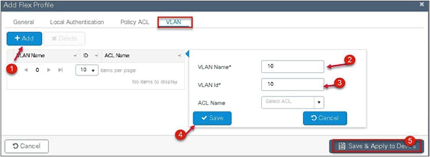
Step 4. Assign the ACL on the flex profile by mapping the VLAN and ACL.
Define the native VLAN for the FlexConnect APs.
Step 5. Push the ACL to AP by using the policy ACL configuration on the flex profile.
Step 6. Verification on the controller.
Navigate to Monitoring > Wireless > Clients.
Procedure for VLAN ACL
● Create an ACL on the controller.
● Create a flex profile and add a VLAN mapped to the WLAN.
● Map the ACL on the VLAN interface.
● Connect the client and validate that the ACL works.
Procedure
Step 1. Create an ACL on the WLC by navigating to Configuration > Security > ACL.
Step 2. Perform the steps below:
● Click on “Add” to create an ACL and define an ACL name.
● Specify the type of ACL: standard or extended.
● Define the rules for the ACL.
● Specify the action as permit or deny.
● Add the ACL rules and save the ACL.
Step 3. Refer to the steps in the procedure of the advanced configuration wizard for the following:
● Create a WLAN
● Creation of policy profile
● Policy tag mapping
● Flex profile creation
● Creation of site tag
● Tagging the AP
Advanced wireless setup wizard:
The ACL is attached to the WLAN through the policy profile.

Step 4. Assign the ACL on the flex profile by mapping the VLAN and ACL.
Define the native VLAN for the FlexConnect APs.
Step 5. Define the VLAN and ACL mapping on the flex profile.
● This feature allows application of the per-client ACL for locally switching WLANs.
● Client ACL is returned from the AAA server on successful client authentication.
● The AP needs to be provisioned with the ACL by using the policy ACL or dummy VLAN ACL mapping on the flex profile.
● The ACL will be pushed to all the APs that have the same site tag and policy tag mapped.
● In the case of central authentication, when the controller receives the ACL from the AAA server, it will send the ACL name to the AP for the client. For locally authenticated clients, the ACL name will be sent from the AP to the controller as part of CCKM/PMK cache, which will then be distributed to all APs belonging to the same site tag and policy tag.
Procedure for client ACL
● Create an ACL on the controller.
● Create a dot1x-based SSID.
● Enable AAA override on the policy profile.
● Return the ACL name as part of the AAA access-accept from the AAA.
For the creation of the ACL, refer to the steps in the WLAN ACL use case. Refer to step 5 in the WLAN ACL section to push the ACL on to the AP.
Procedure for WLAN ACL:
For creating a dot1x WLAN and enabling AAA override, refer to the procedure section of the VLAN override use case.
Procedure
Step 1. Authorization profile on ISE for returning ACL as an AAA attribute.

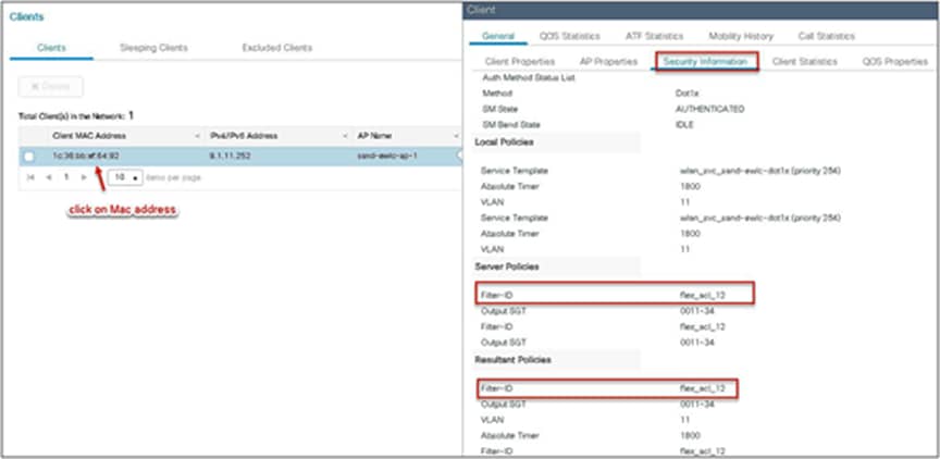
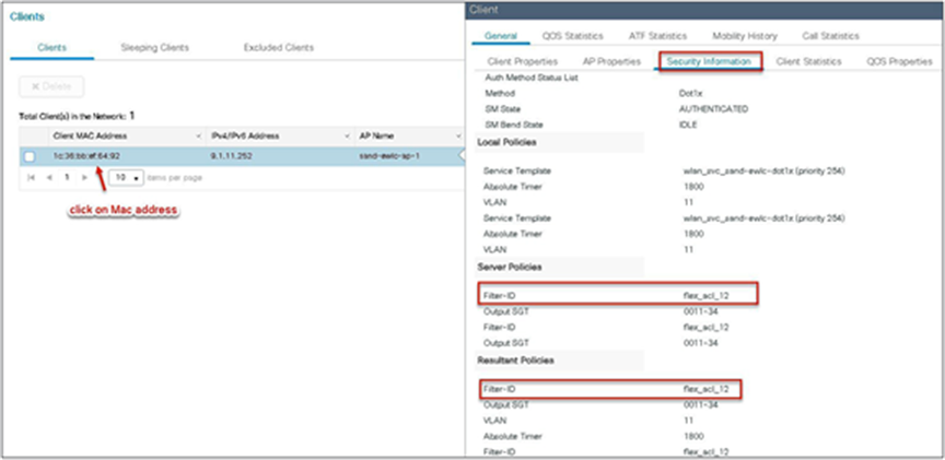
Step 2. Verification of ACL getting enforced on the AP and WLC.
Navigate to Monitor > Wireless > Clients.
Limitations
● The use of downloadable ACL is not supported on FlexConnect local switching. The downloadable ACLs are only supported for central switching.
● In case of central authentication if an ACL is returned from the AAA server but the corresponding ACL is not present on the AP, the client will be excluded with the reason being ACL failure.
● In the case of local authentication, the client will be de-authenticated continuously.
This feature allows the AP to download code while it is operational. The AP pre-image download is extremely useful in reducing the network downtime during software maintenance or upgrades. For the AP pre-image download to work, the controller should be in install mode of operation. If the controller is running in bundle mode, first have it converted to install mode before proceeding to AP pre-image download.
● Ease of software management
● Schedule per branch updates: NCS or Cisco Prime® is needed to accomplish this
● Reduces downtime
Procedure
Step 1. Copy the image on the controller flash and the add the file using the install command:
wlc-2#install add file bootflash:wlc9500C-universalk9.BLD_V1610_THROTTLE_ 010435.SSA.bin
The install file command runs base compatibility checks on a file to ensure that the package is supported on the platform. It also adds an entry in the package, so that its status can be monitored and maintained.
Step 2. Once the file is added, the image can be pushed to the AP using the following CLI:
“ap image predownload”
Once the download is completed on the AP, issue the following CLI to swap the image and reset the AP:
● ap image swap
● ap image reset
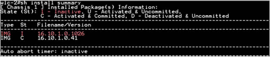
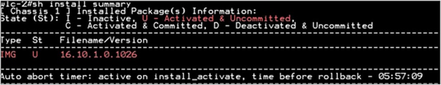
Step 3. After the AP has been reset, use the following CLI to activate the image on the controller:
“Install Activate”
The Install Activate runs compatibility checks, installs the package, and updates the package status details. For a non-restartable package, it triggers a reload. The systems will prompt for saving the config and a reboot during the process.
Please input the response to save the config and reboot the WLC.
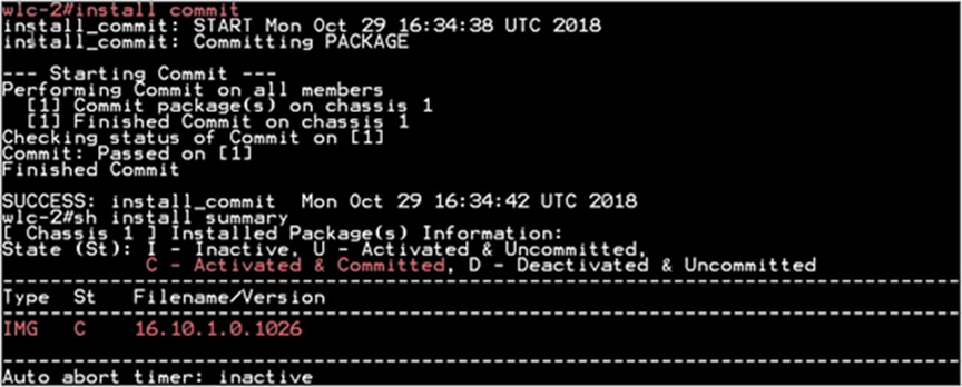
Step 4. Once the system is rebooted, use the following CLI to have the changes persist across reboot.
“Install Commit”
This commits the activation changes to be persistent across reloads The commit can be done after activation while the system is up, or after the first reload. If a package is activated but not committed, it remains active after the first reload, but not after the second reload.
The controller needs to be in install mode for the AP pre-image to work. If a controller works in bundle mode, it needs to be converted to install mode. Please refer to Cisco.com for the conversion for bundle mode to install mode.
FlexConnect smart AP image upgrade
The pre-image download feature reduces the downtime duration to a certain extent, but still, all the FlexConnect APs have to pre-download the respective AP images over the WAN link with higher latency.
Efficient AP image upgrade will reduce the downtime for each FlexConnect AP. The basic idea is only one AP of each AP model will download the image from the controller and will act as Primary/Server, and the rest of the APs of the same model will work as Secondary/Client and will pre-download the AP image from the primary. The distribution of AP images from the server to the client will be on a local network and will not experience the latency of the WAN link. As a result, the process will be faster.
FlexConnect Smart AP Image Upgrade Mechanism
● Primary and secondary APs are selected for each AP model per site tag
● Primary downloads image from WLC
● Secondary downloads image from primary AP using TFTP
● Reduces downtime and saves WAN bandwidth
● The primary is chosen by the system. The AP with the lowest MAC among the same type and model is to become a primary
Procedure
Step 1. For steps to create a flex profile and to have it applied on the AP, refer to the steps in the advanced config wizard section of the document.
Enable smart AP image upgrade on the flex profile.
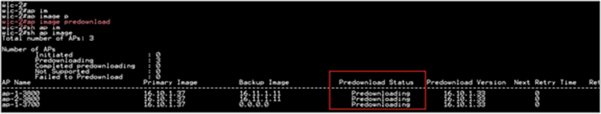
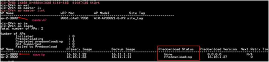
Step 2. Download the image on the controller as outlined in step 1 of the AP image pre-download process. Issue the CLI below to initiate the smart AP image upgrade and also to see the primary AP elected for a given type of AP and the primary downloading image from the controller.
AP Pre-Image Download
ap image predownload site-tag <site_name> start
It is important to give the site tag and start the pre-image download process, as this would initiate the smart AP image upgrade process. If the site tag is not specified, the download falls back to the normal pre-image download process.
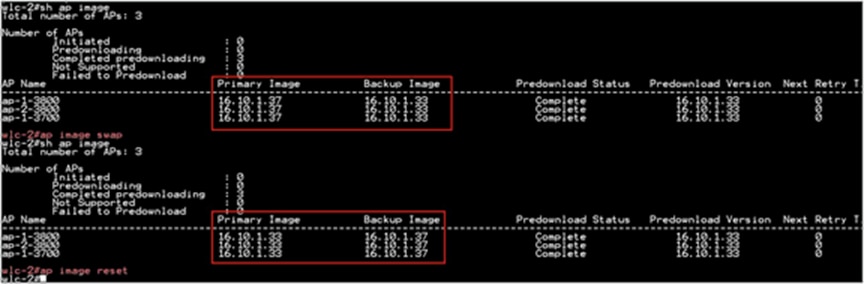
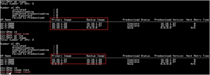
Step 3. After the image pre-download on the AP is completed, follow the sequence below:
● Swap the AP image and reset the AP using the CLI “ap image swap” and “ap image reset.”
● Activate the image using the “Install Activate” CLI.
● During the activation, the WLC will go for a reboot. Use the CLI “Install Commit” to persist the changes across the reboot.
Limitation
The system decides on the election of a primary AP, and the decision on who the primary is decided when the smart AP image download process is initiated. Once the decision is made, any AP that joins after and which has a lower MAC will not alter or change the primary AP already elected.
FlexConnect pre-auth ACL and URL filtering
The URL filtering is an extension to the ACL deployments currently in place. With the addition of URL filtering, the ACL can accept internet domain names in addition to the existing IP address rules. The FlexConnect deployments support the LWA, CWA, and BYOD flow. The LWA refers to the local web authentication done on the WLC while the CWA refers to the guest authentication done on the Identity Service Engine. The BYOD flow requires access to the app store for downloading the supplicant for which URL filters can be used. The use of URL filter can also be extended to CMX connect social login where the authentication happens on the social network site.
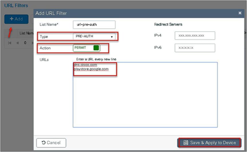
Pre-auth ACL refers to a state when a wireless client would require access to resources before getting authenticated. In the case of LWA/CWA or BYOD, the client might require access to resources before getting full access to the network. The URL filtering for flex is supported only on the Wave 2 platforms. The URL filtering follows a permit list and block list model of working. The administrator can specify up to 20 URLS within a URL filter. The URL filter supports wild-card matching to support sub-URL matching.
For e.g.:
| URL type |
Definition |
| cisco* |
match any URL that starts with Cisco |
| *cisco.com |
match any URL that ends in cisco.com |
| match the exact string |
The URL-filtering ACL works along with a regular ACL to have the URL ACL pushed to a flex AP. It needs to be linked with a regular ACL in the flex profile. The URL ACL works by snooping the DNS transaction between the DNS client and a DNS server. For flex deployment, the DNS snooping is performed on the AP for each client. With snooping in place, the AP learns the IP address of the resolved domain name in the DNS response.
If the domain name matches the configured URL, then the DNS response is parsed for the IP address, and the IP address is mapped in the ACL for locally switched traffic. The rules created from DNS parsing have a permit or deny based on the URL filtering rules, which is either permit listing or block listing. When a packet from or to a client traverses through the AP, the DNS rules are processed first before proceeding with the regular ACL processing. The URL filtering is an optional configuration on the LWA and CWA flow.
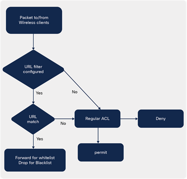
URL-filtering ACL logic
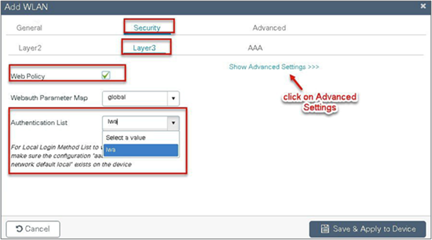
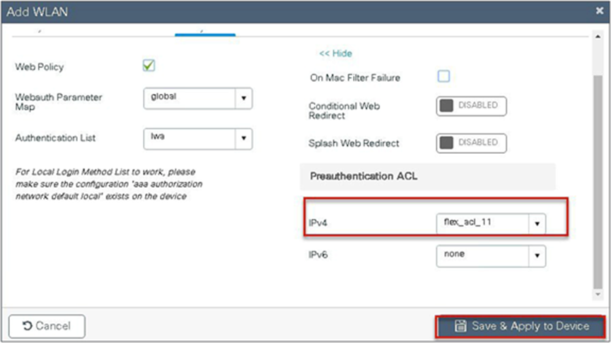
This section describes the steps to set up LWA with pre-auth ACL and URL filter. For the local web authentication, the pre-auth ACL and URL filtering is optional.
Procedure
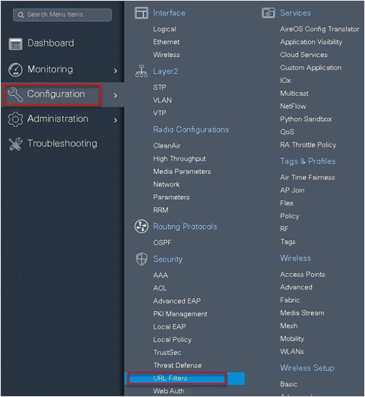
Step 1. To create a URL filter, navigate to Configuration > Security > URL Filters.

Step 2. Create a URL filter.
Step 3. Create an ACL on the WLC to link with the URL ACL.
Step 4. Create an authentication list on the WLC to be used on the LWA WLAN. The authentication list can point to a radius server or can do a local lookup.
Navigate to Configuration > Security > AAA.

Step 5. Create a WLAN to local web-authentication flow.
Navigate to Configuration > Tags & Profiles > WLAN.
Step 6. Create a policy profile.
Step 7. Create a flex profile.
Navigate to Configuration > Tags & Profiles > Flex.
Step 8. Create a site tag mapping the policy tag and flex profile.
Navigate to Configuration > Tags & Profiles > Tags.

Step 9. Map the tags on the AP. Once the APs are tagged with a policy profile, the APs will reboot due to conversion from local mode to FlexConnect mode.
If the APs are already in flex mode, the reboot wouldn’t be triggered.
Navigate to Configuration > Wireless Setup > Advanced.

This section describes the steps to set up CWA with the URL filter. For CWA flow, the URL filter is optional.
● Create a server and server group for MAC auth and AAA attributes.
● Create an authorization list on the controller.
● Create a MAB SSID and map the authorization list on the SSID.
● Create a redirect ACL and a URL filter (optional) on the controller.
● Bind the URL filter and ACL on the flex profile.
● Create an authorization profile on ISE to return the url-redirect and url-redirect-acl Cisco AV pair.
Procedure
Step 1. Create an authentication and authorization list on the WLC.
Navigate to Configuration > Security > AAA.
Use the AAA wizard to create the server and server groups.
Step 2. Define a name for the server and specify the IP address and shared secret.

Step 3. Create a server group and map the server in the group.
Step 4. Enable dot1x system control and checkmark the authentication and authorization profile.
Step 5. Define the method type as dot1x and map the server group.
Step 6. Define the method type as “network” and map the server group.

Step 7. Create a MAB SSID and map the authorization method list.
Navigate to Configuration > Tags & Profiles > WLAN.

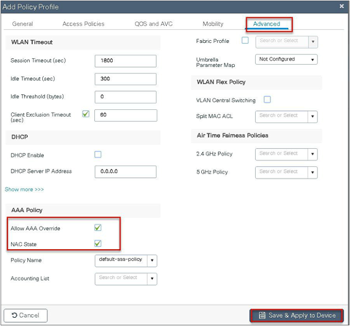
Step 8. Enable the following on the policy profile:
● Local VLAN present on the AP (mapped in the flex profile)
● AAA override
● NAC
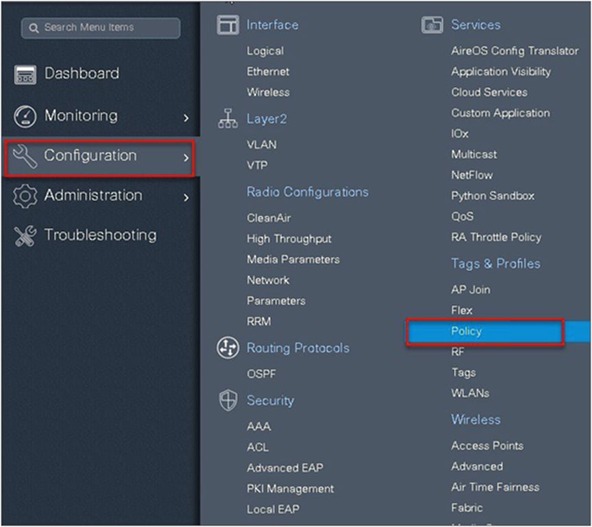
Navigate to Configuration > Tags & Profiles > Policy.
Step 9. Map the policy profile to the WLAN in the policy tag.
Navigate to Configuration > Tags and Profiles > Tags.

Step 10. Create a redirect ACL and an optional URL filter. The option to create a URL filter depends on access to resources during the pre-auth phase.
To create a redirect ACL, use the CLI on the controller. Have the rules created as shown below:
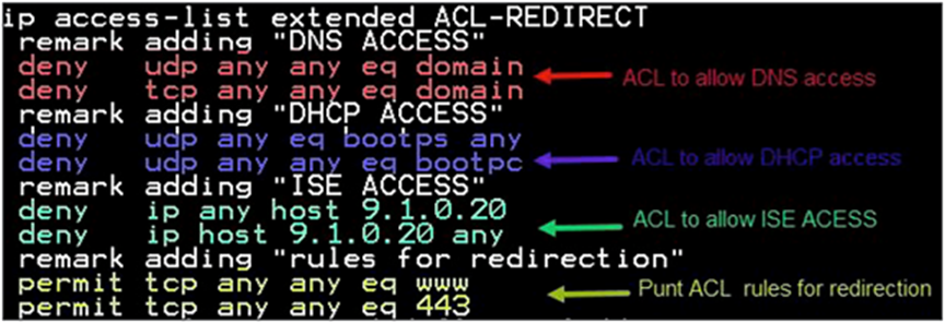
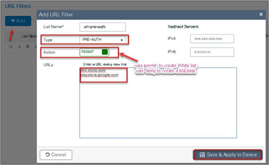
To create a URL filter, navigate to Configuration > Security > URL Filters.
Step 11. Create a URL filter.
Permit action creates a permit list, while the deny action creates a blacklist.
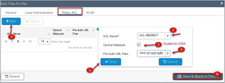
Step 12. Enable the following on the flex profile.
Navigate to Configuration > Tags and Profiles > Flex.
● Local VLAN needs to be configured
● ACL and URL filter needs to be mapped

Step 13. For assigning the flex profile on the site tag and mapping it on the AP, refer to the steps in the advanced configuration wizard of this document.
Step 14. Create an authorization profile and rule on ISE to return the CWA attributes.
For more details on ISE rules and configuration, please refer to the deployment guide:
● The URL filter is only supported on Wave 2 APs and is not supported on Wave 1 APs.
● Post-auth support for URL filter is not supported for local switched clients.
Client association limit per WLAN/AP
The client limit per WLAN features addresses the requirement when an administrator would want to restrict the number of clients accessing the wireless service — for example, limiting total guest clients from branch tunnelling back to the data center.
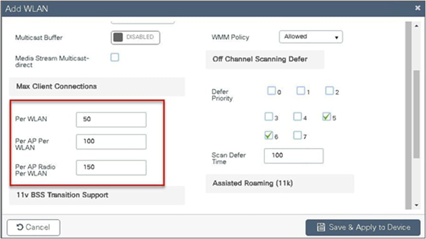
The controller supports limiting the number of client associations in the following ways:
Per-WLAN basis – here the client association is limited on a per-WLAN basis
Per-AP per-WLAN – here the client association is limited on a per-WLAN per-AP basis
Per-AP radio per-WLAN – client association limited on a per-radio per-WLAN basis
To enable a WLAN, please refer to the section of setting up the WLAN in the advanced wireless setup wizard of this document.
Procedure
During the WLAN configuration phase, enable the feature.
This feature does not enforce client limit when the FlexConnect is in the standalone state of operation.
FlexConnect fault tolerance allows wireless access and services to branch clients when:
● FlexConnect branch APs lose connectivity with the primary controller.
● FlexConnect branch APs are switching to the secondary controller.
● FlexConnect branch APs are re-establishing connection to the primary controller.
FlexConnect fault tolerance along with local authentication on the FlexConnect AP provides zero branch downtime during a network outage. This feature is enabled by default and cannot be disabled. It requires no configuration on the controller or AP. To ensure fault tolerance works smoothly, both the controllers need to have identical configs such as:
● WLANM config and policy profile
● AP join profile/flex profile
● RF profile and RF tag
● Site tag
The management IP address of the controller can be different. An administrator can take a backup config of the primary controller and have it installed on the secondary controller to maintain config consistency.
● FlexConnect will not disconnect clients when the AP is connecting back to the same controller provided there is no change in configuration on the controller.
● FlexConnect will not disconnect clients when connecting to the backup controller provided there is no change in configuration and the backup controller is identical to the primary controller.
● FlexConnect will not reset its radios on connecting back to the primary controller provided there is no change in configuration on the controller.
● Supported on both Wave 1 and Wave 2 APs.
● Supported only for FlexConnect with central/local authentication with local switching.
● Centrally authenticated clients require full re-authentication if the client session timer expires before the FlexConnect AP switches from standalone to connected mode.
● FlexConnect primary and backup controllers must be in the same mobility domain.
VideoStream for FlexConnect local switching
This feature enables the wireless architecture to deploy multicast video streaming across the branches, just like it is currently possible for enterprise deployments. This feature recompenses the drawbacks that degrade the video delivery as the video streams and clients scale in a branch network. VideoStream makes video multicast to wireless clients more reliable and facilitates better usage of wireless bandwidth in the branch.
On a traditional WLAN network, multicast and broadcast are sent out over the wireless medium at the lowest data rate with no acknowledgement and the packet delivery for such streams is on a best-effort basis. This makes the usage of multicast unreliable on a WLAN network. The usage of multicast for delivering critical applications has become a demand and need of the hour. There is also a need to differentiate multiple streams and assign priority and weightage based on the applications supported. With the adoption of 802.11ac and the data rates supported, it is possible to deliver multicast streams using the data rates available on 11ac with reliability and priority built in.
● VideoStream provides efficient bandwidth utilization by removing the need to broadcast multicast packets to all WLANs on the AP
● Supported on Wave 1 and Wave 2 APs
● Supported for FlexConnect local switching and central authentication
● With VideoStream in FlexConnect local switching, the multicast to unicast conversion happens on the AP
● The branch infrastructure should have multicast-enabled
● Admission control is currently not supported
● IPv6 support for media stream is not supported
The section below details the procedure for configuring media streams from the controller. It is expected that the branch network will be enabled for multicast.
Please ensure the following multicast features are enabled on the network.
● Multicast routing protocol – PIM sparse/dense mode
● IGMP version 2 or 3
● IGMP snooping
This section doesn’t cover enabling multicast on the infrastructure other than on the wireless controller.
Procedure for enabling VideoStream
The steps here include only the changes to enable VideoStream.
The advanced configuration section can be used to set up the SSID, profiles, and tags. The section below details the configuration of the media stream on the 5 GHz radio.
Procedure
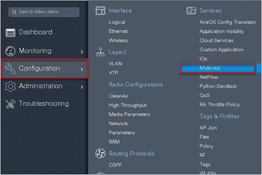
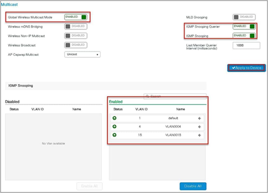
Step 1. Enable multicast globally on the controller.
Navigate to Configuration > Services > Multicast.
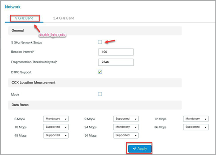
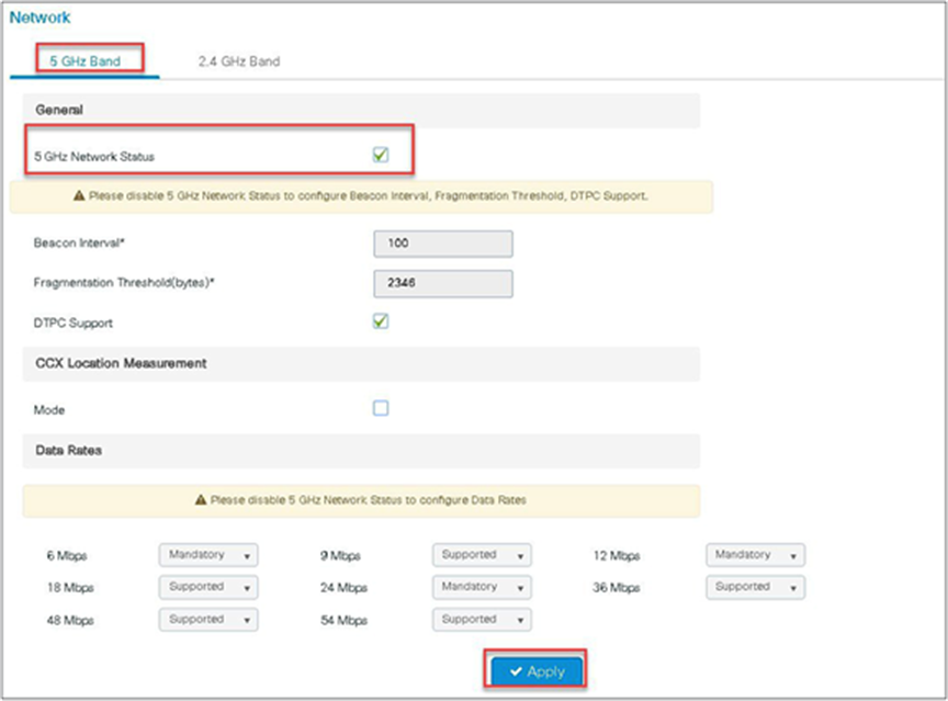
Step 2. Enable media stream on the dot11 interface.
Disable the appropriate radio interface before enabling the media stream.
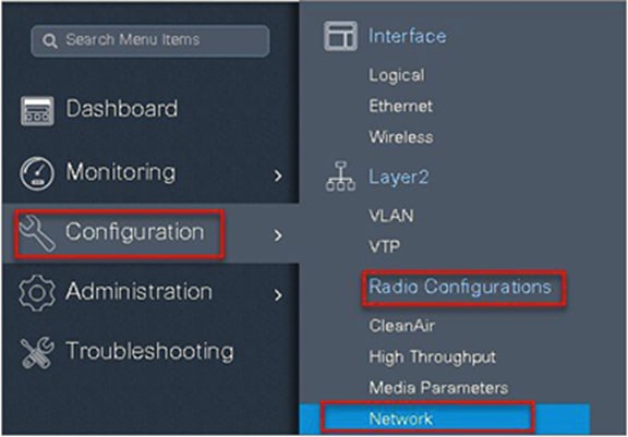
Navigate to Configuration > Radio Configurations > Network.
Disable 5 or 2.4 GHz radio. In this example, we are enabling media streaming on 5 GHz radio.
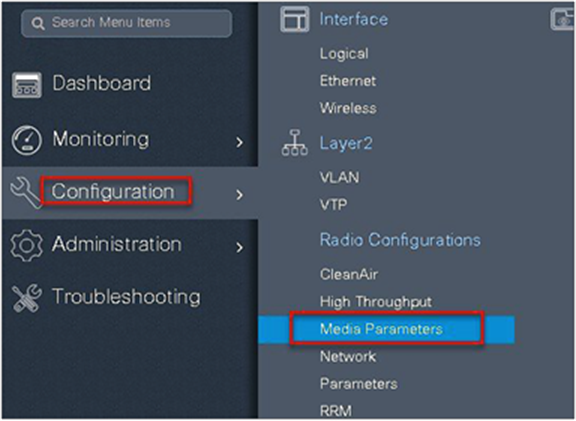
Step 3. Navigate to Configuration > Radio Configurations > Media Parameters.
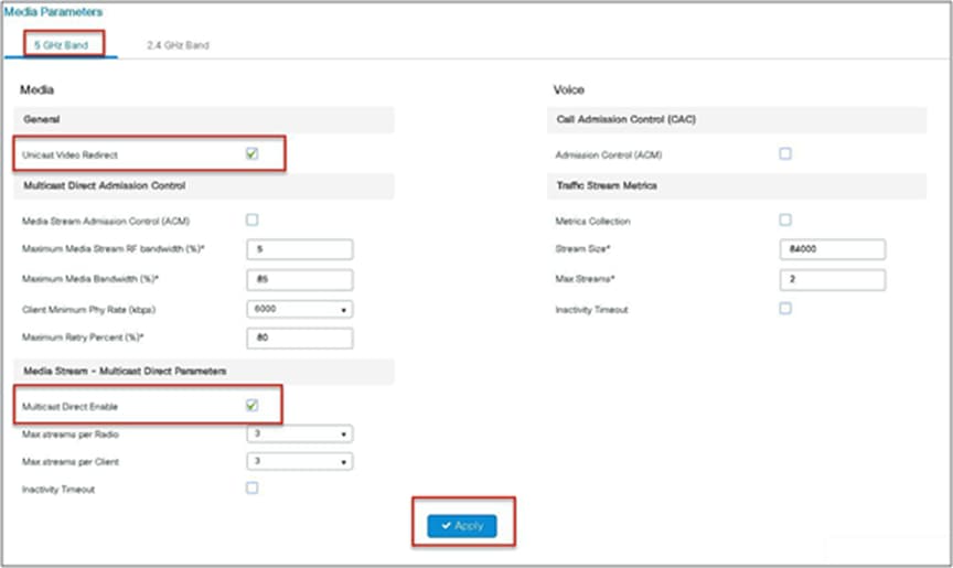
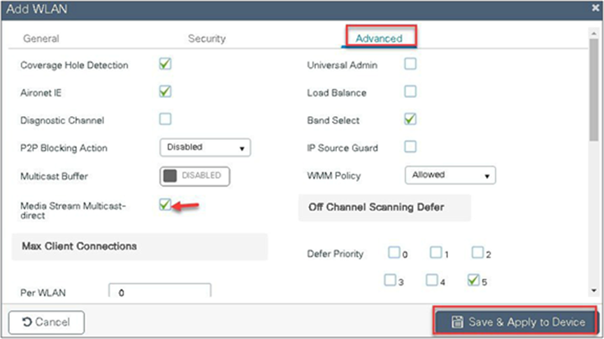
Step 4. Enable the media stream on the WLAN creation page on the advanced tab. Refer to the advanced configuration wizard section for WLAN creation.
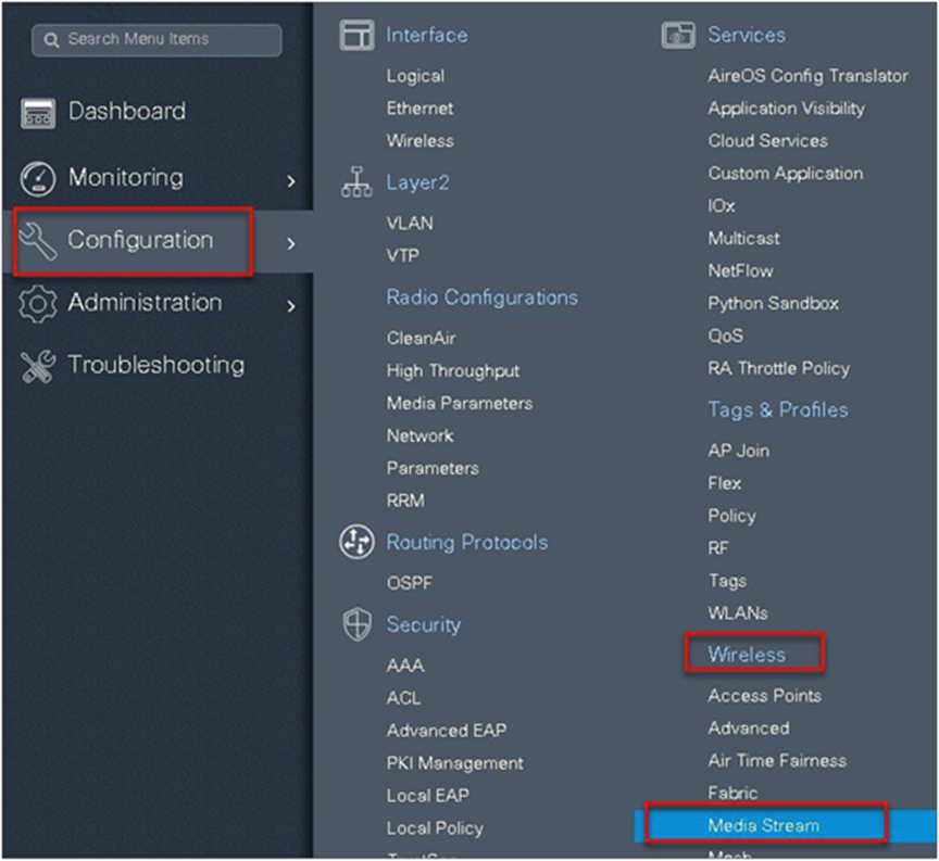
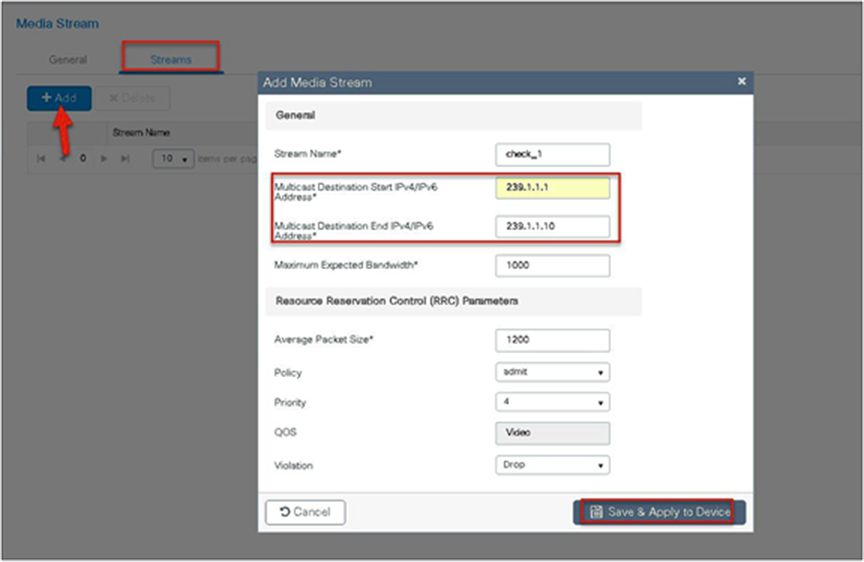
Step 5. Define the media stream multicast address configuration.
Navigate to Wireless > Media Stream.

Step 6. Enable the dot11 interface on which the media stream was enabled.
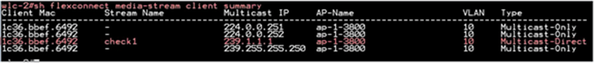
Connect the wireless client and subscribe to the respective multicast video stream.
Issue the CLI “show flexconnect media client summary” to see the multicast transmission being classified as multicast direct/video stream.
Multiple customers tend to use cookie-cutter configurations across the sites and branches. This includes local or DHCP servers configured with the same subnet. Before 17.4, the controller detected this is IP THEFT and clients would be blacklisted.
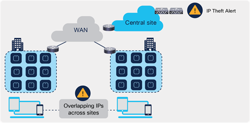
Behavior of overlapping IPs across sites before Release 17.4
Release 17.4 adds support for overlapping IP addresses across different flex sites.
For this to work, every site needs to be assigned to a unique site-tag > C9800 uses the combination of site-tag + IP address as a unique ID for the client (called zone-id).
It is important to note that this is only available for Flex local DHCP/ local switching; for all other deployments (local mode, central switching, central DHCP, etc.), overlapping IPs are still not supported.
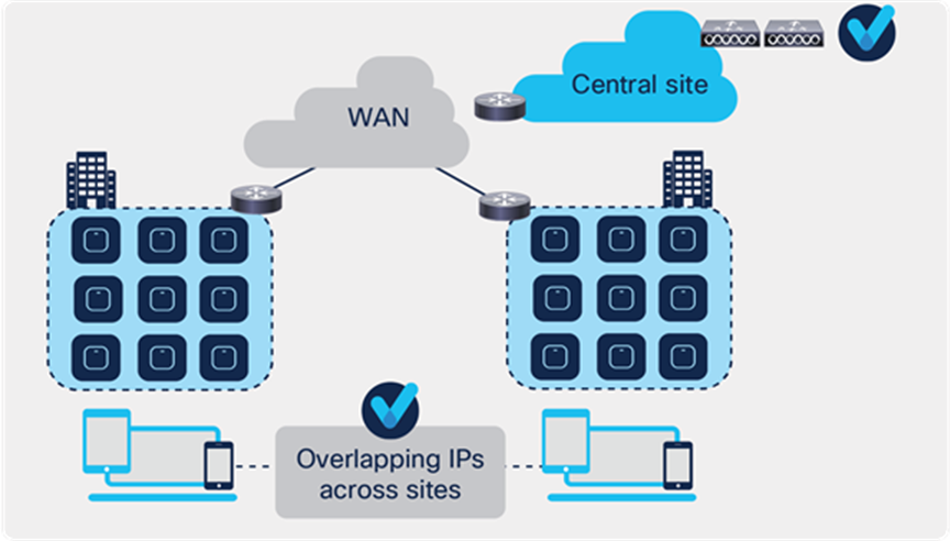
Behavior of overlapping IPs across sites starting Release 17.4
This feature is supported on all C9800 appliances (physical and virtual). It is not supported on EWC on Catalyst AP and Catalyst 9k switch because these are meant for single site deployments.
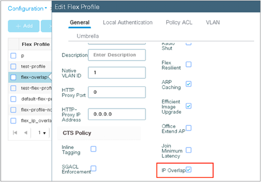
Procedure for enabling Flex IP Overlap
Enable and disabling the feature is controlled via the config knob under the Flex Profile.
The equivalent CLI command is:
(config)#wireless profile flex flex1
(config-wireless-flex-profile)#ip overlap
To verify execute the following command:
9800-wlc#show wireless profile flex detailed flex1
Fallback Radio shut : DISABLED
ARP caching : ENABLED
Efficient Image Upgrade : ENABLED
OfficeExtend AP : DISABLED
Join min latency : DISABLED
IP overlap status : ENABLED
“Show wireless device-tracking database ip <ip>” CLI will not be supported when IP overlap feature is enabled. Any filtering based on IP or Zone should be performed only on “Show wireless device-tracking database ip”.
9800-wlc#show wireless device-tracking database ip
ZONE-ID IP STATE DISCOVERY MAC
-----------------------------------------------------------------------------------------
0x00000004 21.21.0.1 Reachable IPv4 Packet 74da.3864.2a83
0x0000000c 21.21.0.1 Reachable IPv4 DHCP 74da.3873.2a8b
0x8000400a fe80::76da:38ff:fe64:2a83 Reachable IPv6 Packet 74da.3864.2a83
0x8000c00a fe80::76da:38ff:fe73:2a8b Reachable IPv6 Packet 74da.3873.2a8b
In order to enable or disable the Overlap IP Support which are part of the flex profile, following NETCONF RPC is defined
<nc:rpc xmlns:nc="urn:ietf:params:xml:ns:netconf:base:1.0" message-id="urn:uuid:a90868eb-1b78-43b4-a949-2dca79687a69">
<nc:edit-config>
<nc:target>
<nc:running/>
</nc:target>
<nc:config>
<flex-cfg-data xmlns="http://cisco.com/ns/yang/Cisco-IOS-XE-wireless-flex-cfg">
<flex-policy-entries>
<flex-policy-entry>
<policy-name>Flex_profile</policy-name>
<description/>
<ip-overlap-cfg>
<flex-overlapping-ip-enable>true</flex-overlapping-ip-enable>
</ip-overlap-cfg>
</flex-policy-entry>
</flex-policy-entries>
</flex-cfg-data>
</nc:config>
</nc:edit-config>
</nc:rpc>
● VLAN: virtual LAN
● RF: radio frequency
● FT: fault tolerance
● WAVE 1 AP: AP which supports WAVE 1 802.11ac (Cisco 3700)
● WAVE 2 AP: AP which supports WAVE f2 802.11ac (Cisco 1800/2800/3800/4800)
● WLC: wireless LAN controller