Cisco Traditional Wired and Wireless Local Mode Bonjour Deployment Guide
Available Languages
Bias-Free Language
The documentation set for this product strives to use bias-free language. For the purposes of this documentation set, bias-free is defined as language that does not imply discrimination based on age, disability, gender, racial identity, ethnic identity, sexual orientation, socioeconomic status, and intersectionality. Exceptions may be present in the documentation due to language that is hardcoded in the user interfaces of the product software, language used based on RFP documentation, or language that is used by a referenced third-party product. Learn more about how Cisco is using Inclusive Language.
Bonjour technology invented and standardized by Apple introducing zero-configuration solution that simplifies network configuration and enables communication between connected devices, services, and applications. Bonjour leverages link-local Multicast DNS and it is designed to enable peer-to-peer communication on single Layer 2 domains that are ideal for small, flat, single-domain setups, such as home networks.
The mDNS enabled services on consumer products, digital conference room, IoT and more is pervasive in service-oriented Enterprise network. The Cisco DNA Service for Bonjour solution eliminates the single Layer 2 domain constraint and expands the scope to enterprise-grade traditional wired and wireless networks, next-generation fabric-based overlay networks such as Cisco Software-Defined Access (SD-Access) and industry-standard BGP EVPN with VXLAN. The Cisco Catalyst 9000 series LAN switches and Cisco 9800 series wireless LAN controllers follow the industry standard, RFC 6762-based multicast DNS (mDNS) specification to support interoperability with various compatible wired and wireless consumer products in enterprise networks.
The Enterprise networks are going through constant digital transformation as more and more smart and services-rich devices are being connected. While every device is designed with different purposes, the user-centric application and operational simplicity in their operation remains the core focus in technology. The plug-n-play service discovery and distribution using Bonjour technology in networks eases the IT operation for managing devices.
The IT administrator faces several challenges in large and complex Enterprise networks to seamlessly introduce an Bonjour technology that is originally designed to operate in a single Layer 2 broadcast domain. Since the proliferation of Bonjour devices and mandatory services requirements the networking vendors introduced gateway solution that allows services discovery between local network segments. The solution overcomes initial challenge but continue to be limited as the service discovery and distribution up to single gateway only, without any end-to-end solution. The centralized architecture of single gateway quickly become bottleneck as network expands demanding more scale and performance impacting other core networking function. Figure – 1 below illustrates the Bonjour challenges and requirements for Enterprise networks.
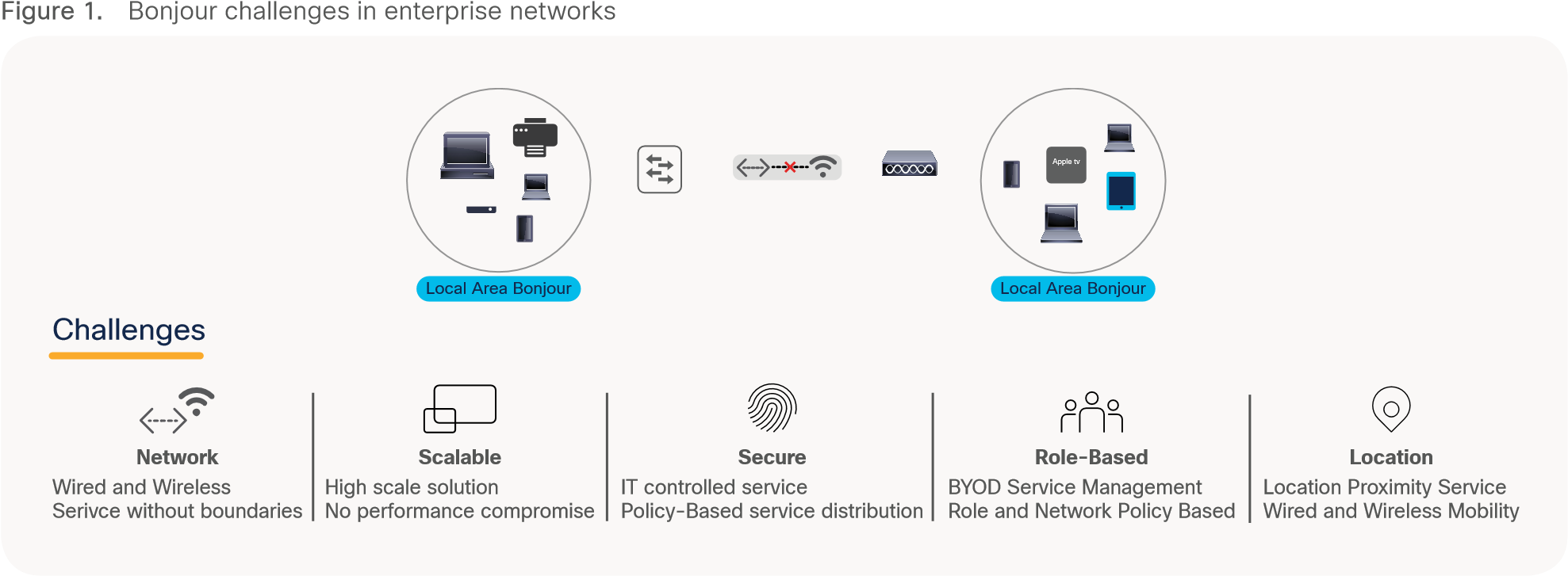
Bonjour Challenges in Enterprise Networks
The industry and Enterprise networks adopted classic solution by extending network-wide Layer 2 flood boundaries to central Wireless LAN Controller (WLC) service gateway point to discover and distribute services to the Wireless users. This classic mDNS service bridging capabilities is known as “service-on-a-stick” model due to the lack of mDNS service routing capabilities on Enterprise networking products. Figure – 2 below illustrates various commonly deployed Enterprise Wireless network and classic flood-n-learn basis mDNS gateway solution:
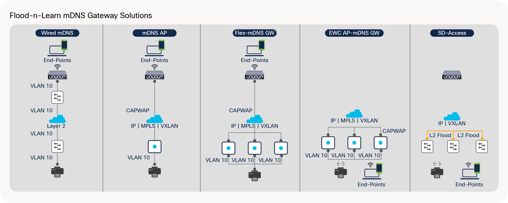
Classic Service-on-Stick mDNS Gateway Alternatives
The classic single-WLC mDNS gateway feature have been effectively working in small to mid-size Enterprise network environment. As the network expands multi-dimensionally with increased endpoints counts, next-generation consumer OS introducing new intuitive services leveraging underlying mDNS protocol and network size growth may introduce new set of overall scale, security, and performance challenges.
Cisco DNA Service for Bonjour Solution Overview
The Cisco Digital Network Architecture (DNA) Service for Bonjour solution enables end-to-end Bonjour service-routing securely between Enterprise-grade advanced Wired and Wireless networks. The Cisco DNA Service for Bonjour solution also addresses problems relating to security, policy enforcement, and services administration on a large scale. The new distributed architecture is designed to eliminate mDNS flood boundaries and transition to unicast-based service routing, providing policy enforcement points and enabling the management of Bonjour services. With the Cisco DNA Service for Bonjour solution, the Enterprise networks can seamlessly introduce new services into the existing enterprise environment without modifying the existing network design or configuration.
The enhanced intuitive Cisco DNA-Center Wide Area Bonjour application GUI provides centralized access control and monitoring capabilities, combined with the scalability and performance required for large-scale Bonjour services deployments for various supporting enterprise network types.
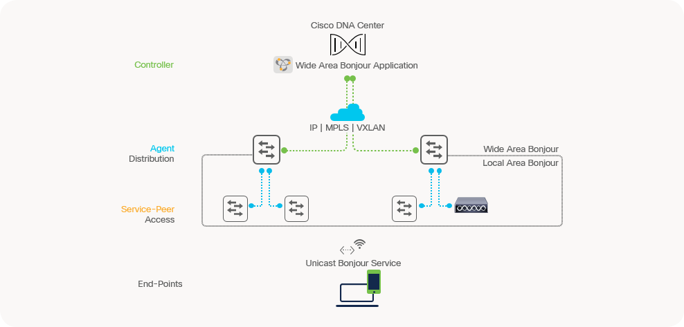
The following Figure – 3 illustrates how the Cisco DNA Service for Bonjour operates across two integrated Wired and Wireless networks with end-to-end unicast-based service routing.
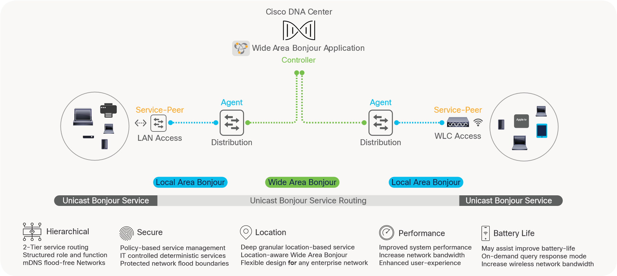
Cisco DNA Service for Bonjour Solution
The hierarchical service-routing architecture in Cisco DNA Service for Bonjour solution is divided in following two domains:
● Local Area Bonjour Domain – The Local Area Bonjour consist of single IP network block, i.e., single IP gateway switch in distribution layer connecting to multiple downstream Layer 2 Switch, WLC and Access-Points. The unicast-based mDNS service routing boundary is limited within Local Area Bonjour domain across multiple Layer 2 network devices providing services in same or different VLANs. The Cisco Catalyst 9000 series switches and Cisco Catalyst 9800 series wireless LAN controllers in Layer 2 mode introduce a new Service-Peer role and replaces classic un-secure flood-n-learn to unicast service-routing model. Cisco DNA-Center is optional.
● Wide Area Bonjour Domain – The Wide Area Bonjour domain is required when mDNS services needs to be discovered beyond single IP network boundary. Cisco DNA-Center is required for meet such requirement. The Cisco Catalyst 9000 series switches as IP gateway shall be enabled in SDG agent mode to establish a lightweight, stateful, and reliable communication channel with Cisco DNA Center running the Cisco Wide Area Bonjour application. The Service routing between the SDG agents and the controller operates over regular IP network to support policy and location based mDNS service management.
Cisco DNA Service for Bonjour Solution Benefits
The Cisco DNA Service for Bonjour solution replaces mDNS flood-n-learn based service discovery and distribution to Unicast mode thru end-to-end hierarchical service-routing in Enterprise networks. The RFC 6762 based mDNS endpoints communicates with first-hop Wired and Wireless mDNS gateways must adhere IT defined policies to securely routed within Layer 2 network boundary and beyond. Figure – 4 below illustrates difference between classic mDNS flood-n-learn and new Cisco unicast-based mDNS routing model solving known challenges pertaining to discovery boundaries, scale, security and more.
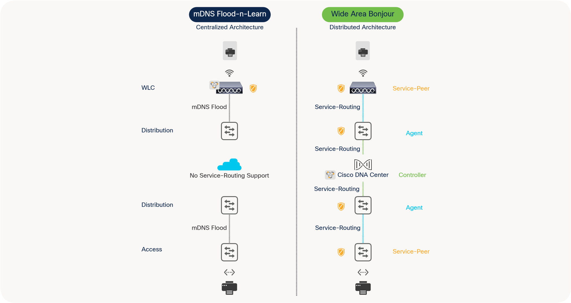
Cisco DNA Service for Bonjour Solution Benefits
Following sub-section highlights key benefits of Cisco DNA Service for Bonjour solution across Enterprise grade Wired and Wireless networks:
● End-to-End – The Cisco DNA Service for Bonjour solution extends mDNS service discovery and distribution across Enterprise-grade Wired and Wireless networks without network boundaries. The Enterprise IT can build end-to-end, hierarchical, and structured service-oriented networks without introducing forklifting network re-design.
● Scale – The distributed mDNS service-routing solution across LAN and WLC systems decouples classic and centralized mDNS processing of WLC as single-gateway for entire network.
● Secure – The Enterprise IT gains control to introduce new services based on policy set on location, by role and more. The new Unicast-based model eliminates flood-n-learn based mDNS service model thus un-checked or out-of-policy services are implicitly denied using as consumer products introduces new capabilities.
● Experience – The end-user service discovery and distribution experience remain intact between residential and secure Enterprise networks. With zero learning-curve and agent-less mDNS service-routing solution, the IT can adapt new services as introduced in consumer products as they evolve without forklift network infrastructure redesign.
The Cisco DNA Service for Bonjour solution is an end-to-end solution that includes the following key components and system roles to enable unicast-based service routing across the Local Area and Wide Area Bonjour domain. Table – 1 below provides complete Cisco DNA Service for Bonjour solution matrix, service-routing support over commonly deployed Enterprise networks, operation and more.
Table 1. Cisco DNA Service for Bonjour Solution Support Matrix
|
|
Cisco DNA-Center Appliance |
Wide Area Bonjour App |
Catalyst 9600 |
Catalyst 9500 |
Catalyst 9400 |
Catalyst 9300 |
Catalyst 9200 |
Catalyst 9800 WLC |
| Platform Series |
DN2-HW-APL DN2-HW-APL-L DN2-HW-APL-XL |
|
Any |
Any |
Any |
Any |
Catalyst 9200 |
Any |
| Minimum Software |
2.2.2.0 |
2.2.2.0 |
17.6.2 |
17.6.2 |
17.6.2 |
17.6.2 |
17.6.2 |
17.6.2 |
| Supported Role |
Platform |
Controller |
SDG-Agent Service-Peer |
SDG-Agent Service-Peer |
SDG-Agent Service-Peer |
SDG-Agent Service-Peer |
SDG |
Service Peer |
| Wide-Area Support |
─ |
● |
● |
● |
● |
● |
Not Supported |
─ |
| Local-Area Support |
─ |
● |
● |
● |
● |
● |
● |
● |
| Service Scale |
─ |
150000 |
15000 |
12000 |
10000 |
7500 |
1000 |
14000 |
| Software License |
||||||||
| Local and Wide-Are License |
─ |
─ |
Cisco DNA-Advantage |
Cisco DNA-Advantage |
Cisco DNA-Advantage |
Cisco DNA-Advantage |
Cisco DNA-Advantage |
Cisco DNA-Advantage |
| System Mode |
||||||||
| Cluster |
HA Cluster |
Multi-Instance |
StackWise Virtual |
StackWise Virtual |
StackWise Virtual |
StackWise-480 |
Cisco DNA-Advantage |
HA Cluster |
| Default |
Single Host |
Single Instance |
Standalone |
Standalone |
Standalone |
Standalone |
Standalone |
Standalone |
| Wired/Wireless Network Support |
||||||||
| Wired-Multilayer |
─ |
● |
● |
● |
● |
● |
● |
─ |
| Wired-Routed Access |
─ |
● |
● |
● |
● |
● |
● |
─ |
| Wireless-Local Mode |
─ |
● |
● |
● |
● |
● |
● |
● |
| Wireless-FlexConnect mode |
─ |
● |
● |
● |
● |
● |
● |
Switch Gateway |
| Wireless-Catalyst 9100 EWC Mode |
─ |
● |
● |
● |
● |
● |
● |
Switch Gateway |
| Cisco DNA-Center Appliance |
||||||||
| Cisco SD-Access |
─ |
● |
● |
● |
● |
● |
● |
─ |
| Cisco SD-Access Wireless |
─ |
● |
● |
● |
● |
● |
● |
Switch Gateway |
| BGP EVPN VXLAN |
─ |
● |
● |
● |
● |
● |
─ |
─ |
| MPLS VPN |
─ |
● |
● |
● |
● |
● |
─ |
─ |
| Multi-VRF |
─ |
● |
● |
● |
● |
● |
● |
─ |
| Operation |
||||||||
| Assurance |
─ |
● |
─ |
─ |
─ |
─ |
─ |
─ |
| SNMP MIB Support |
─ |
─ |
● |
● |
● |
● |
● |
─ |
Endpoint Compatibility
As described earlier, the Cisco DNA Service for Bonjour solution follows industry standard RFC 6762 to communicate with Multicast DNS capable endpoints. Thus, the solution is compatible with any vendors following the standards including Apple, Google, Microsoft, Printer manufacturers, Audio/Video endpoints, IOT and many more.
Target Audience
This document is targeted for Enterprise Wired and Wireless network administrators providing guidance on designing and deploying end-to-end Bonjour services. The content of this document primarily focuses on how to enable Bonjour services seamlessly into various types of Enterprise networks designs and topologies. This deployment guide provides guidance to evaluate existing network designs and system inventory along with simple step-by-step configurations guidelines for successful deployments.
This document does not cover basics of Bonjour implementation and it is highly recommended to refer to Apple Bonjour Overview document and RFC 6762 to learn Bonjour terminologies and operation.
Cisco DNA Service for Bonjour Architecture
The Cisco DNA Service for Bonjour solution supports three-tier distributed service-routing solution across broad-range of complex Enterprise network designs. The mDNS service-routing build secure, targeted and stateful peering and operates on network devices and optionally with central Cisco DNA-Center controller if the service discovery is required beyond single IP network boundary. The mDNS service-routing does not interfere with existing Unicast or Multicast routing-protocols as it is designed to dynamically discover and distribute mDNS services from local Layer 2 network and route across complex Wired and Wireless networks based on Enterprise IT defined granular policies.
This sub-section describes network device modes, functions, and broad range of supporting traditional LAN and Wireless network designs in Enterprise. The distributed service-routing architecture of Cisco DNA Service for Bonjour assists in building scalable, reliable, and resilient solution. The IT can design traditional LAN and Wireless network with multi-tier mDNS service-routing to replace end-to-end mDNS flood-n-learn in Enterprise with hierarchical and structured Unicast service-routing. Figure 5 – below illustrates multi-tier service-routing architecture overview:
Cisco DNA Service for Bonjour Architecture
● Cisco DNA controller: The Cisco DNA controller builds the Wide Area Bonjour domain with network-wide and distributed trusted SDG agents using a secure communication channel for centralized services management and controlled service routing.
● SDG Agent: The Cisco Catalyst 9000 series switch functions as an SDG agent and builds reliable communication with Cisco DNA-Center. In Layer 3 Access mode, it communicates with directly attached mDNS service endpoints. In Layer 2/3 Distribution mode, it builds unicast-based service-routing with downstream Layer 2 Cisco Catalyst 9000 series switch or Cisco Catalyst 9800 series WLC to dynamically discover, aggregate and exports information to the Cisco DNA controller based on policy.
● Service Peer: At first hop the Layer 2 Cisco Catalyst 9000 series switch and Catalyst 9800 series Wireless LAN Controller (WLC) shall be configured in Service-Peer mode. It enables policy-based unicast communication with local attached endpoints in same or different VLANs and export service information to the upstream Cisco SDG agent in the distribution layer.
● Endpoints: A mDNS endpoint is any device that advertises or queries mDNS services conforming to RFC 6762. The mDNS endpoints can be in either LANs or WLANs. The Cisco Wide Area Bonjour solution is designed to integrate with RFC 6762 compliant Bonjour services, including AirPlay, Google Chrome cast, AirPrint, Dante Audinate and more.
Local Area Bonjour Service-Routing
The Local Area Bonjour consists multiple Layer 2 Ethernet switches, WLC or Access-Points network devices providing unicast-based mDNS service-routing across same or different VLANs following IT defined policies. The Distribution layer Ethernet switch provides IP and service-routing gateway function between all Wired and Wireless end points across Layer 2 network and eliminating mDNS flood from the network. The Cisco DNA-Center requirement is optional and can be deployed to enable mDNS service assurance.
The Cisco DNA Service for Bonjour solution supports various Enterprise-grade large scale LAN and Wireless network designs. Depending on implemented network design the mDNS gateway mode settings for Layer 2 Ethernet switch, WLC and Access-Points series may vary. This sub-section provides brief overview of Local Area Bonjour service-routing across commonly deployed LAN and Wireless network models. Figure – 6 below illustrates various Local Area Bonjour deployment models for LAN and Wireless network supporting unicast-based service-routing to directly attached mDNS endpoints:
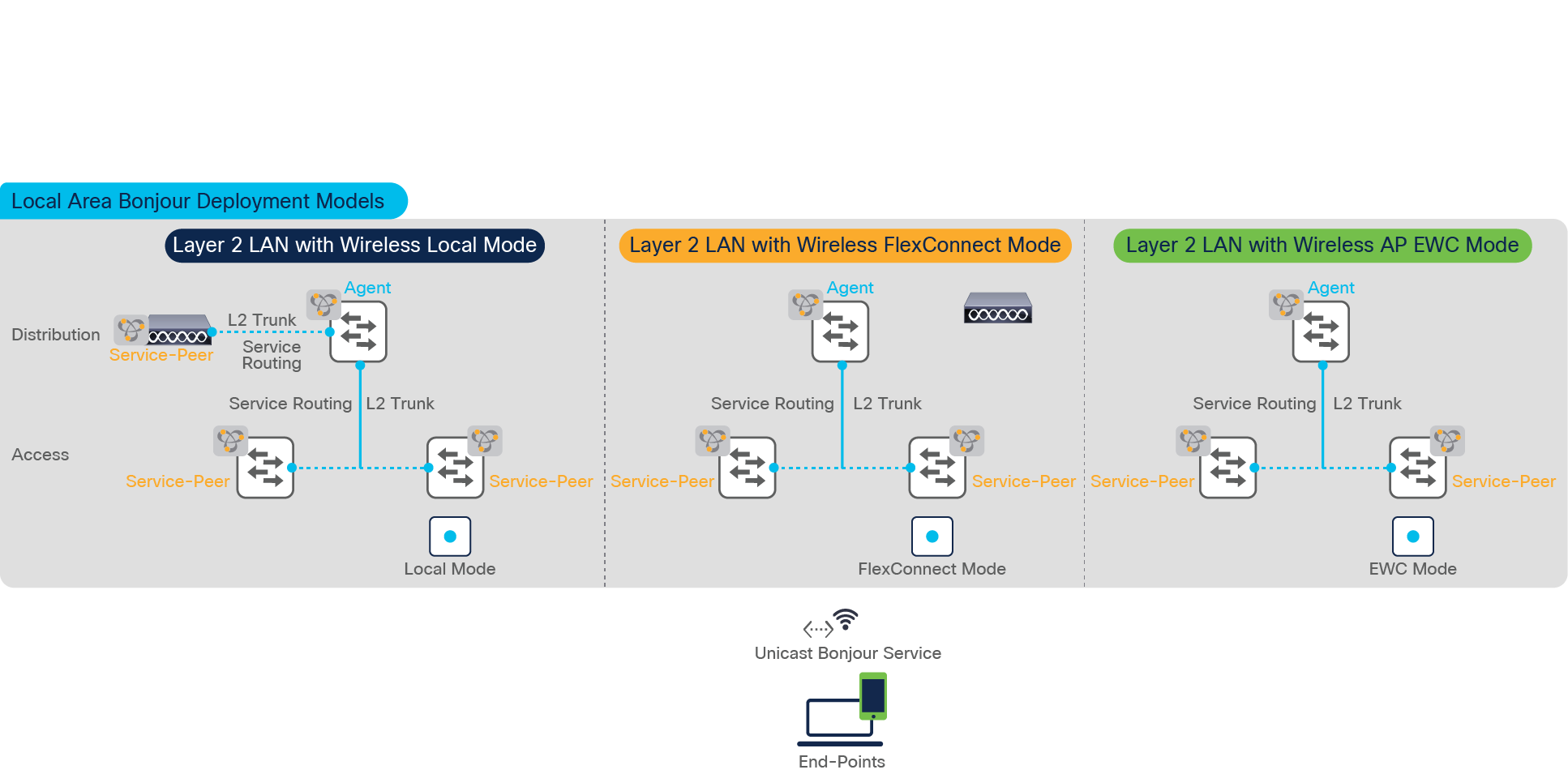
Local Area Bonjour Design Alternatives
Wide Area Bonjour Service-Routing
The Wide Area Bonjour is borderless service-routing solution that enables IT defined policy and location-based mDNS service discovery from one network point to other across IP, MPLS or VXLAN fabric enabled core backbone. The IP gateway Cisco Catalyst switch for LAN or Wireless networks builds stateful service-routing communication with Cisco DNA Center to export dynamically discovered mDNS services or relay remote service discovery request received from local Wired and Wireless network. The IT can design and build common or customized to limit mDNS policy between Local and Wide Area Bonjour domains, i.e., Apple TV and Printer shall be discovered over Wide Area Bonjour domain, however Apple ScreenShare or Real VNC should be limited within Local Area Bonjour domain boundary.
This sub-section provides brief overview of Wide Area Bonjour service-routing across commonly deployed across LAN and Wireless network across Enterprise core backbone networks. Figure – 7 below illustrates various Enterprise-grade LAN and Wireless network designs supporting unicast-based service-routing to directly mDNS endpoints:
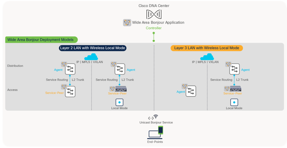
Wide Area Bonjour Design Alternatives
The network remains unsecure and vulnerable to support mDNS security in classic flood-n-learn based networks. The network administrators have limited controls and visibility to identify, secure and manage mDNS services in Layer-2 network environments. As Cisco Catalyst LAN switching and Wireless portfolio introduces unicast-based mDNS service management it enables new possibilities for IT organizations to build end-to-end secure service-routing solution in enterprise networks.
The Cisco IOS-XE 17.6.2 software version introduces new flexible policy configuration model providing network administrator to design and build simplified or custom tailored mDNS service-routing Wired and Wireless networks. Figure 8 – below illustrates the new Cisco IOS-XE built-in default policy model to activate unicast-based mDNS service-routing on intended Wired VLAN or Wireless Profile. The Cisco Catalyst switch and WLC continue to support of custom mode policy when upgrading from previous software version or need tailored policies solution.
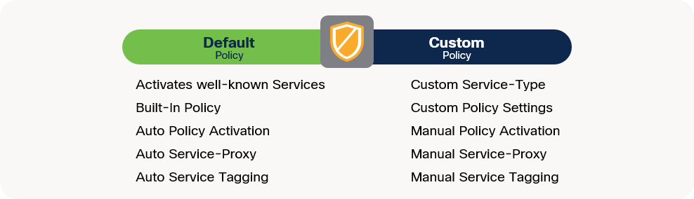
Flexible Cisco IOS-XE Service-Routing Policy Modes
The Cisco IOS-XE provides support co-existence of Default and Custom policy on same Catalyst 9000 series switch and 9800 series WLC system. Based on requirement the administrator can implement policy in either or both mode on per Wired VLAN and Wireless Profile basis:
Table 2. Flexible Cisco IOS-XE Service-Routing Policy Comparison
|
|
Default Mode |
Custom Mode |
| Local Area Bonjour – Service-List Permit |
Built-In. Default bi-directional services permitted* |
Custom. User-defined uni-directional custom service permission |
| Local Area Bonjour – Service-Policy |
Built-In. Automatically binds default Service-List |
Custom. User-defined custom service-list binding |
| Local Area Bonjour – Service-Policy |
Built-In. Automatically associates default policy to mDNS gateway enabled Wired VLAN and Wireless Profile |
Custom. User-defined manual policy association to mDNS gateway enabled Wired VLAN and Wireless Profile |
| Local Area Bonjour – Wired Inter-VLAN Service-Proxy |
Built-In. Automatic Inter-VLAN Service-Proxy on L2 Switch |
Custom. User-Defined manual Inter-VLAN location-filter on L2 Switch |
| Wide Area Bonjour – Service-List Permit |
Built-In. Default controller services permitted* |
Custom. User-defined controller-bound custom service policy |
| Wide Area Bonjour – Service-Policy |
Built-In. Automatically binds default controller Service-List |
Custom. User-defined custom controller service-list binding |
| Location-Tag – Wired Port and Local Mode AP |
Built-In. Default Tag (0) to Wired Port and Local Mode AP |
Built-In or Custom. Default Tag (0) or custom tag assigned to Wired Port and Local Mode AP |
|
|
As a best practices, the network administrator shall evaluate right policy mode that fits business requirements. The default mode may fit well in fully distributed Wired and Wireless networks. In large scale centralized Wireless Local Mode environment, the hybrid policy mode can be adopted with LAN network deployed default mode, however the Catalyst 9800 WLC system performance with Custom mode to protect system scale and performance. |

Location-Group Based Service-Routing
The classic mDNS flood-n-learn based network deployments was able to build mDNS policies based on variable Wireless Access-Points attributes, i.e., AP Name, Location, RRM etc. thus limited to Wireless-only location-based mDNS gateway solution. The key challenge on LAN side is to dynamically identify, tag and extend granular location details for Wired mDNS services connection. It has not been possible when bridge-domain size for Wired Layer 2 networks varies, and are across multi-hop away from WLC performing central processing.
Cisco DNA Service for Bonjour solution enables zero-configuration vision with introduction of mDNS service-routing based on Location-Group ID tags assigned to Wired LAN Ports and Cisco Wireless Access-Points. The Cisco Catalyst LAN switches, Catalyst 9800 series WLC and Cisco DNA-Center expands policy capabilities with inclusion of matching Location-Group ID tag to discover and distribute mDNS services. The mDNS service Location-Group tag on Wired LAN Ports and Wireless Access Points are dynamically synchronized across complex Enterprise network environments and without introducing forklift Wired and Wireless network changes impacting mission-critical network environments.

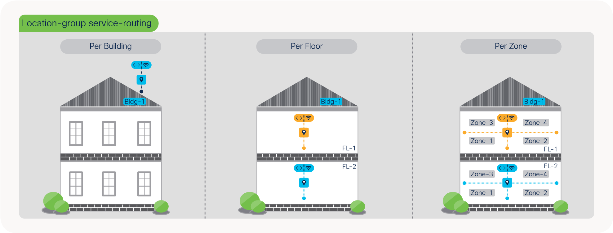
Location-Group Based Service-Routing
As end-to-end mDNS processing transforms to unicast-based service and provides flexibility to tag mDNS services for granular service-routing, the Cisco DNA Service for Bonjour enables new possibilities for IT organization. To provide the best-in-class user-experience the IT administrator can design and build Location-Group tag based dynamic mDNS service boundaries at individual building, floor, or micro-segmented service-zones on each floor. As mDNS service discovery boundary shrinks the user-experience improves in easily navigating limited IT managed or Peer-to-Peer service provider list within tailored close-proximity.
The IT organization can design and build mDNS policies enabling secure service experience to the end-users, i.e., In Bldg-1, James can discover and use Wired Apple-TV and Printer from his iPhone. In Bldg-2, James should only see Apple-TV and he shall not be able to find any mDNS services when connected to Bldg-3 wired or wireless network. Figure – 10 below illustrates some common Location-Group tag use-cases that IT can enable across Enterprise Wired and Wireless networks:
Location-Group Based mDNS Use-Cases
Deploying Local Area Bonjour Domain
The network remains unsecure and unmanageable to enforce mDNS security in classic flood-n-learn based networks. The network administrators have limited controls and visibility to identify, secure and manage mDNS services in Layer-2 network environments. As Cisco Catalyst LAN switching and Wireless portfolio introduces unicast-based mDNS service management it enables new possibilities for IT organizations to build end-to-end secure service-routing enterprise networks.
This section provides guidelines to implement unicast-based mDNS service-routing in Local Area Bonjour domain that is common deployment model supporting collapsed Wired and Wireless networks to common IP gateway switch in Distribution layer. As described earlier, the Local Area Bonjour consists of multiple Layer 2 Ethernet switches, Wireless controllers and Access-Points connecting to some common IP gateway for their Wired and Wireless endpoints. For such deployment models, the Cisco DNA-Center is optional capabilities that can provide central service assurance capabilities.
This Local Area Bonjour domain supports Wireless in Local, FlexConnect and EWC mode in enterprise networks. This guide focuses on Cisco Catalyst 9800 series Wireless LAN controller deployed with Local mode Access-point. Refer to Cisco DNA Service for Bonjour : Cisco FlexConnect Bonjour Deployment Guide for other deployment reference. Figure – 11 below illustrates reference unicast-based Local Area Bonjour domain enabling service-routing capabilities between Layer 2 Ethernet switches and Cisco Catalyst 9800 series WLC.
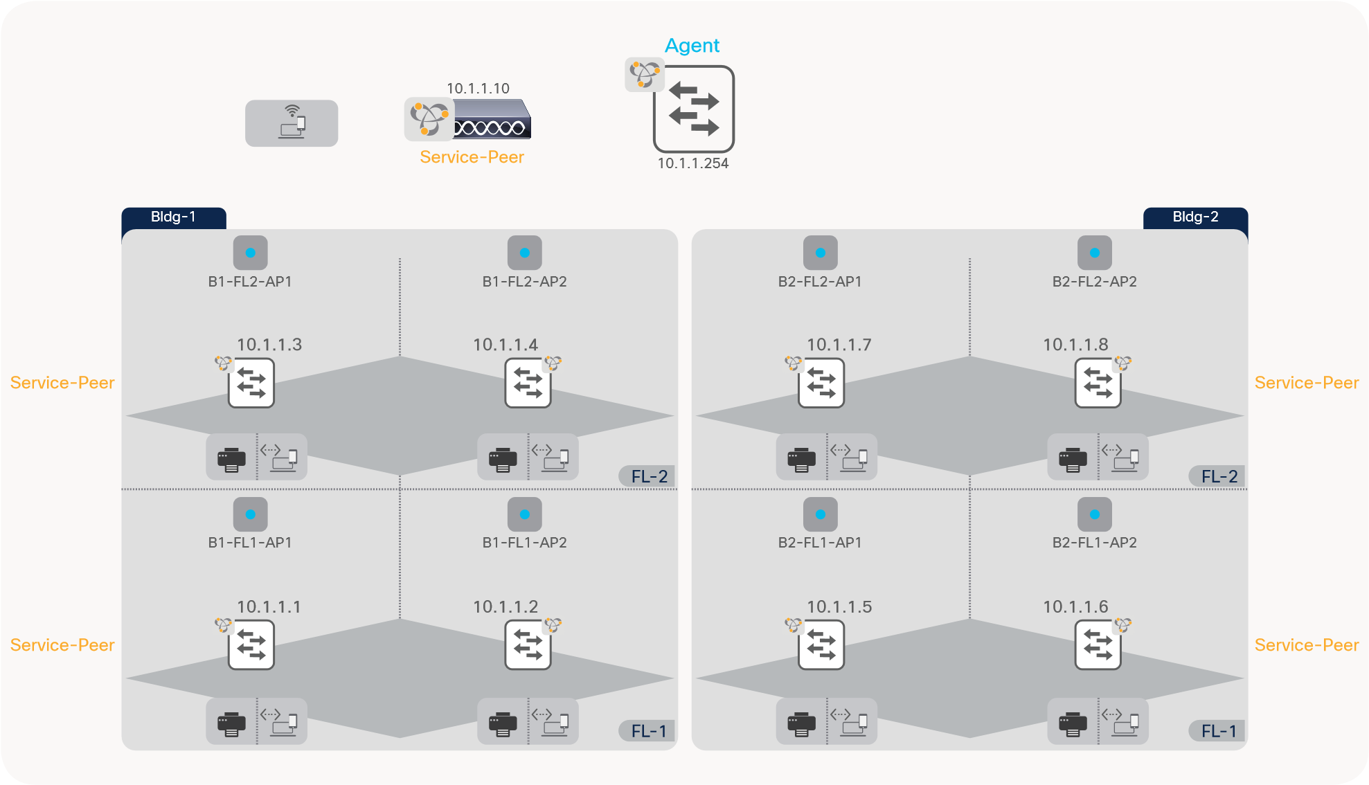
Unicast-based Local Area Bonjour Design
Local Area Bonjour Pre-Requisite Configuration
Prior configurating mDNS service-routing capabilities it is imperative basic pre-requisite configurations are applied on targeted network devices to successfully implement unicast-based mDNS service-routing:
● Software and License – The minimum software version Cisco IOS-XE 17.6.2 and network devices with DNA-Advantage license is required to implement capabilities described in this guide.
● IP Reachability – Ensure the LAN Access and WLC in Service-Peer mode have basic IP connectivity in same VLAN and subnet with Distribution-layer SDG Agent switch. The existing LAN and WLC management VLAN can be leveraged to enable service-routing.
● IP Multicast – Ensure Cisco Catalyst 9800 WLC is enabled with AP Multicast and the network is configured with IP Multicast routing allowing Cisco Wireless Access Points in Local Mode joining IP Multicast group announced by WLC. The IP Multicast on Wired and Wireless Client interface is optional and not required for mDNS.
● Wireless Client SVI – Ensure Cisco Catalyst WLC is configured with Wireless Client SVI interface with valid IP address to successfully enable mDNS gateway function for Wireless clients.
● Wireless AP Name – Ensure the Wireless APs name is defined matching to their location, i.e., B1-FL1-AP-1 to match individual or group of APs based on regular expression.
|
|
Wireless SSID downtime should be planned to activate mDNS and Location-Group tag function on targeted Wireless SSID and Access-Points. |
This section provides the reference configuration guidelines using default and custom mode for collapsed Wired and Wireless networks as illustrated reference network design in Figure – 11. Table – 3 below provides the default mode policy side-by-side reference configuration enabling mDNS service-routing between Layer 2 Ethernet switch, WLC in Service-Peer mode and the IP gateway enabled as SDG Agent. In this mode, several well-known white-listed mDNS service-types are by default permitted in Local Area Bonjour domain.
Default Policy Mode Configuration
Table 3. Local Area Bonjour Service-Routing with Default Mode Policy Configuration
| LAN-Access |
Distribution |
WLC |
| Service-Peer |
Agent |
Service-Peer |
| Step – 1: Default Mode – mDNS Service-Routing |
||
| ! ! Printer and User VLAN mdns-sd gateway ! |
! vlan configuration 11,12, 101 ! Printer, Wired User VLAN, Wireless User VLAN Range mdns-sd gateway |
! mdns-sd-interface gateway ! |
| Step – 2: Default Mode – mDNS Trusted Service-Routing Interface |
||
| ! description TO DIST |
! interface Po1 description TO LAN ACCESS interface Po2 description TO WLC |
Default mDNS trust mode. No configuration required. |
| Step – 3: Default Mode – Enable Inter Service-Peers Service-Routing |
||
|
|
! mdns-sd service-peer group peer-group 1 service-policy default-mdns-service-policy service-peer 10.1.1.1 location-group default … service-peer 10.1.1.8 location-group default service-peer 10.1.1.10 location-group default ! |
|
Custom Policy Mode Configuration
The advanced mode mDNS service-routing can be deployed with user-defined custom policy for Wired and Wireless networks. The Cisco IOS-XE built-in default mode mDNS policy is replaced with custom policy once applied under targeted Wired VLAN or on Wireless Profile. The default and custom mode policy can co-exist on same mDNS gateway system, hence based on requirements the Cisco IOS-XE provides flexible solution to use default and custom policy on same Catalyst Ethernet switch and WLC system.
Table – 4 below provides the custom mode policy reference configuration enabling mDNS service-routing on Layer 2 LAN Access Ethernet switch, Catalyst 9800 series WLC and LAN Distribution Layer switch as illustrated reference network design in Figure – 11.
Table 4. Local Area Bonjour Service-Routing with Custom Mode Policy – LAN Access Switch Configuration
| LAN-Access |
Distribution |
WLC |
| Service-Peer |
SDG-Agent |
Service-Peer |
| Step – 1: Custom Mode – LAN Distribution SDG-Agent Service-Routing |
||
| ! interface Po1 description TO DIST |
! vlan configuration 11,12, 101 ! Printer, Wired User VLAN, Wireless User VLAN Range mdns-sd gateway ! interface Po1 description TO LAN ACCESS interface Po2 description TO WLC |
! |
| Step – 2: Custom Mode – mDNS Service-Policy |
||
| ! LAN-Access, Distribution and WLC Configuration ! mdns-sd service-list LOCAL-AREA-BONJOUR-IN IN match apple-airprint ! mdns-sd service-list LOCAL-AREA-BONJOUR-OUT OUT match apple-airprint ! mdns-sd service-policy LOCAL-AREA-BONJOUR-POLICY service-list LOCAL-AREA-BONJOUR-IN IN service-list LOCAL-AREA-BONJOUR-OUT OUT ! |
||
| Step – 3: Custom Mode – LAN Access Inter-VLAN Service Local Proxy |
||
| ! mdns-sd location-filter LOCAL-PROXY match location-group default vlan 11 ! mdns-sd service-list LOCAL-AREA-BONJOUR-OUT OUT match apple-airprint location-filter LOCAL-PROXY |
|
|
| Step – 4: Custom Mode – mDNS Service-Policy Association |
||
| ! Wired Printer (11) and User VLAN (12) ! vlan configuration 11,12 ! mdns-sd gateway service-policy LOCAL-AREA-BONJOUR-POLICY |
! vlan configuration 11,12, 101 ! Printer, Wired User VLAN, Wireless User VLAN Range mdns-sd gateway ! mdns-sd service-peer group peer-group 1 service-policy LOCAL-AREA-BONJOUR-POLICY service-peer 10.1.1.1 location-group default … service-peer 10.1.1.10 location-group default ! |
! wireless profile policy WLAN-PROFILE mdns-sd service-policy LOCAL-AREA-BONJOUR-POLICY ! wlan EDU 1 EDU mdns-sd-interface gateway ! |
Deploying Wide Area Bonjour Domain
The Wide Area Bonjour domain is required when mDNS service discovery crosses single SDG Agent or IP network boundary. The Cisco DNA-Center is required for Wide Area Bonjour supporting central service-routing and assurance capabilities. The network-wide distributed Cisco Catalyst 9000 series switches in SDG Agent mode builds stateful and reliable communication with Cisco DNA-Center. The network administrator shall define Wide Area Bonjour global policy on Cisco DNA-Center to dynamically discover and distribute mDNS service information based on policy and location-based between SDG-Agents.
This section provides guidelines to implement unicast-based mDNS service-routing in Wide Area Bonjour domain that is common deployment model supporting Wired and Wireless networks to multiple IP gateway SDG Agent switches that are distributed across IP core backbone network. The IP gateway SDG Agent switches may be deployed in Distribution-layer or Access-layer switches in Layer 3 routing mode. Figure – 12 below illustrates reference unicast-based Local Area and Wide Area Bonjour domain enabling end-to-end service-routing capabilities comprising Wired, Wireless Local Mode and Cisco DNA-Center.
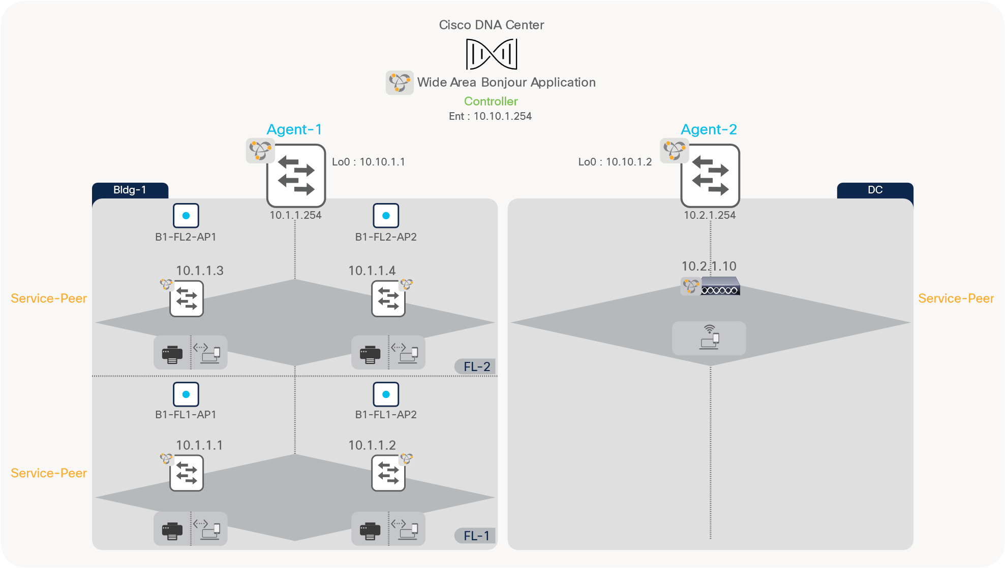
Unicast-based Wide Area Bonjour Design
Wide Area Bonjour Pre-Requisite Configuration
Prior configurating mDNS service-routing capabilities it is imperative basic pre-requisite configurations are applied on targeted network devices to successfully implement unicast-based mDNS service-routing:
● Software and License – The minimum software version Cisco IOS-XE 17.6.2 and network devices with DNA-Advantage license is required to implement capabilities described in this guide.
● Cisco DNA-Center – Ensure all mDNS gateway Ethernet switches and Catalyst 9800 WLC is added in Cisco DNA-Center inventory. Ensure all the devices have successfully reached to Managed state.
● IP Reachability – Ensure the LAN Access and WLC in Service-Peer mode have basic IP connectivity in same VLAN and subnet with their local Distribution-layer SDG Agent switch. The LAN and WLC management VLAN can be leveraged to enable service-routing.
● IP Multicast – Ensure Cisco Catalyst 9800 WLC is enabled with AP Multicast and the network is configured with IP Multicast routing allowing Cisco Wireless Access Points in Local Mode joining IP Multicast group announced by WLC. The IP Multicast on Wired and Wireless Client interface is optional and not required for mDNS.
● Wireless Client SVI – Ensure Cisco Catalyst WLC is configured with Wireless Client SVI interface with valid IP address to successfully enable mDNS gateway function for Wireless clients.
● Wireless AP Name – Ensure the Wireless APs name is defined matching to their location, i.e., B1-FL1-AP-1 to match individual or group of APs based on regular expression.
|
|
Wireless SSID downtime should be planned to activate mDNS and Location-Tag function on targeted Wireless SSID and Access-Points. |
This section provides the reference configuration guidelines based on reference network design illustrated above in Figure – 12 using default and custom mode policy on Cisco Catalyst 9000 series switches and WLC deployed across core backbone network. Table – 5 below provides the default mode policy mode side-by-side reference configuration enabling mDNS service-routing in Local Area Bonjour domain as described previous section and adds Wide Area Bonjour domain to enable service-routing session with Cisco DNA-Center. In this mode, several well-known white-listed mDNS service-types are by default permitted in Local and Wide Area Bonjour domain.
Default Policy Mode Configuration
Table 5. Wide Area Bonjour Service-Routing with Default Mode Policy Configuration
| LAN-Access |
Distribution |
Distribution |
WLC |
| Service-Peer |
LAN Agent – 1 |
WLC Agent – 2 |
Service-Peer |
| Step – 1: Default Mode – mDNS Service-Routing |
|||
| ! ! Printer and User VLAN mdns-sd gateway ! |
! ! ! Printer, Wired User VLAN mdns-sd gateway
|
! ! ! Wireless User VLAN mdns-sd gateway
|
! mdns-sd-interface gateway ! |
| Step – 2: Default Mode – mDNS Trusted Service-Routing Interface |
|||
| ! description TO DIST mdns-sd trust |
! interface Po1 description TO LAN ACCESS |
! interface Po1 description TO WLC |
Default mDNS trust mode. No configuration required. |
| Step – 3: Default Mode – Enable Wide Area Bonjour Service-Routing |
|||
|
|
! LAN Agent-1 and WLC Agent-2 Configuration ! service-export mdns-sd controller DNAC ! |
|
|
| Step – 4: Default Mode – Enable Location-Group Based Service-Routing |
|||
| Refer to Default- Mode Policy Location-Group Service-Routing Section to implement Location-Based service-routing. |
|||
| Step – 5: Enable based Wide Area Bonjour Policy on Cisco DNAC |
|||
| Refer to Deploying Wide Area Bonjour Application Section to implement Bonjour Policy on Cisco DNA-Center. |
|||
Custom Policy Mode Configuration
The advanced mode mDNS service-routing can be deployed with user-defined custom policy for Wired and Wireless networks. The Cisco IOS-XE built-in default mode mDNS policy is replaced with custom policy once applied under targeted Wired VLAN or on Wireless Profile. The default and custom mode policy can co-exist on same mDNS gateway system, hence based on requirements the Cisco IOS-XE provides flexible solution to use default and custom policy on same Catalyst Ethernet switch and WLC system.
Table – 6 below provides the custom policy mode reference configuration enabling mDNS service-routing on Layer 2 LAN Access Ethernet switch, Catalyst 9800 series WLC and LAN Distribution Layer switch.
Table 6. Wide Area Bonjour Service-Routing with Custom Mode Policy Configuration
| LAN-Access |
LAN Distribution |
WLC Distribution |
WLC |
| Service-Peer |
SDG-Agent |
SDG-Agent |
Service-Peer |
| Step – 1: Custom Mode – LAN Distribution SDG-Agent Service-Routing |
|||
| ! interface Po1 description TO DIST |
! interface Po1 description TO LAN ACCESS |
! interface Po1 description TO WLC |
! |
| Step – 2: Custom Mode – mDNS Service-Policy |
|||
| ! LAN Access, LAN Agent-1, WLC Agent-2 and WLC Configuration ! mdns-sd service-list LOCAL-AREA-BONJOUR-IN IN match apple-airprint ! mdns-sd service-list LOCAL-AREA-BONJOUR-OUT OUT match apple-airprint ! mdns-sd service-policy LOCAL-AREA-BONJOUR-POLICY service-list LOCAL-AREA-BONJOUR-IN IN service-list LOCAL-AREA-BONJOUR-OUT OUT ! |
|||
| Step – 3: Custom Mode – LAN Access Inter-VLAN Service Local Proxy |
|||
| ! mdns-sd location-filter LOCAL-PROXY match location-group default vlan 11 ! mdns-sd service-list LOCAL-AREA-BONJOUR-OUT OUT match apple-airprint location-filter LOCAL-PROXY |
|
|
|
| Step – 4: Custom Mode – mDNS Service-Policy Association |
|||
| ! Wired Printer (11) and User VLAN (12) ! vlan configuration 11,12 ! mdns-sd gateway service-policy LOCAL-AREA-BONJOUR-POLICY |
|
|
! wireless profile policy WLAN-PROFILE mdns-sd service-policy LOCAL-AREA-BONJOUR-POLICY ! wlan EDU 1 EDU mdns-sd-interface gateway ! |
| Step – 5: Custom Policy Mode – Wide Area Bonjour Controller Service-Policy |
|||
|
|
! LAN Agent-1 and WLC Agent-2 Configuration ! mdns-sd service-list WIDE-AREA-BONJOUR-OUT OUT match apple-airprint ! mdns-sd service-policy WIDE-AREA-BONJOUR-POLICY service-list WIDE-AREA-BONJOUR-OUT OUT ! |
|
|
| Step – 6: Custom Policy Mode – Wide Area Bonjour Controller Service-Routing |
|||
|
|
! LAN Agent-1 and WLC Agent-2 Configuration ! service-export mdns-sd controller DNAC controller-service-policy WIDE-AREA-BONJOUR-POLICY out ! |
|
|
| Step – 7: Enable based Wide Area Bonjour Policy on Cisco DNAC |
|||
| Refer to Deploying Wide Area Bonjour Application Section to implement Bonjour Policy on Cisco DNA-Center. |
|||
Deploying Location-Group Based Service-Routing
Default Mode Policy Location-Group Service-Routing
The Enterprise organization office size broadly varies by buildings, floors, and outdoor areas. The Location-Group based service-routing may require building tailored service-routing to limit the mDNS service discovery within building to support enhanced user-experience. This sub-section augments Location-Group based service-routing based on above-described default mode configuration in Table – 5.
This section is divided in three most commonly location-based service-routing. Each sub-section provides reference configuration to build policy from broad to deep granular mDNS solution to support intuitive zero-configuration user-experience, network, service security, and more. Based on IT organization requirements, the Location-Group tag and mDNS policies can be adjusted to implement the solution at per-building, per-floor, and per-zone on each floor level.
|
|
The Cisco Catalyst 9800 series WLC do not currently support location-based service-routing with default mode policy. Hence, the custom mDNS service-policy must be configured on Catalyst 9800 WLC to enable location-group based mDNS service-routing. |
Per-Building Location-Group Configuration
The network administrator can group one or more LAN Ethernet switches and logically tag Wireless Access-Points deployed on targeted building across one or more floors. In Wide Area Bonjour domain, the Cisco Catalyst 9000 series switches in LAN distribution-layer can group multiple Service-Peers such as Layer 2 LAN Access switches. Similarly, the WLAN distribution-layer can group one or more Catalyst 9800 WLC to support Location-Group tag assigned to Access-Points on per-building basis. The global policy on Cisco DNA-Center must be configured to allow mDNS service-routing dynamically between LAN and WLAN distribution layer switches based on Location-Group tag ID.
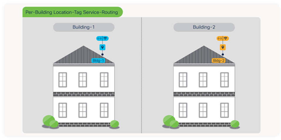
Per-Building Location-Group Service-Routing
Table 7. Per-Building Location-Group Service-Routing Plan
|
|
Building – 1 |
Building – 2 |
| Floor – 1 Group |
LAN Switch IP: 10.1.1.1 – 2 Regex AP Name: B1 |
LAN Switch IP: 10.1.1.5 – 6 Regex AP Name: B2 |
| Floor – 2 Group |
LAN Switch IP: 10.1.1.3 – 4 Regex AP Name: B1 |
LAN Switch IP: 10.1.1.7 – 8 Regex AP Name: B2 |
| WLC Management IP |
10.1.1.10 |
|
Table – 8 below describes step-by-step procedure to build service-routing and enable Location-Group based mDNS service-routing in Wide Area Bonjour domain.
Table 8. Wide Area Bonjour – Per-Building Location-Group Service-Routing Configuration
| LAN Access |
LAN Distribution |
WLAN Distribution |
WLC |
| Service-Peer |
Agent |
Agent |
Service-Peer |
| Step – 1: Default Mode – mDNS Service-Routing |
|||
| ! ! |
|||
| Step – 2: Custom Mode – Catalyst 9800 WLC mDNS Service-Policy |
|||
|
|
|
|
! mdns-sd service-list LOCAL-AREA-SERVICES-IN IN match printer … ! mdns-sd service-list LOCAL-AREA-SERVICES-OUT OUT match printer … ! mdns-sd service-policy LOCAL-AREA-SERVICE-POLICY service-list LOCAL-AREA-SERVICES-IN IN service-list LOCAL-AREA-SERVICES-OUT OUT ! wireless profile policy WLAN-PROFILE mdns-sd service-policy LOCAL-AREA-SERVICE-POLICY ! |
| Step – 3: Per-Building – Enable Location-Group based Service-Routing |
|||
| ! Default Location-Group (0) on LAN switchport. No configuration required. |
! mdns-sd service-peer group ! Create Bldg-1 Service Peer-Group for LAN Switch peer-group 1 service-policy default-mdns-service-policy service-peer 10.1.1.1 location-group default … service-peer 10.1.1.4 location-group default ! peer-group 2 ! Create Bldg-2 Service Peer-Group for LAN Switch service-policy default-mdns-service-policy service-peer 10.1.1.5 location-group default … service-peer 10.1.1.8 location-group default ! |
! Optional. Configure Inter Service-Peer service-routing if more than one WLC attached. |
! ! Create Bldg-1 mDNS AP Group rule-priority 2 rule-name Bldg-2-mDNS ! Create Bldg-2 mDNS AP Group location location-group |
| Step – 4: Enable Location-Group based Wide Area Bonjour Policy on Cisco DNAC |
|||
| Refer to Deploying Wide Area Bonjour Application Section to implement Bonjour Policy on Cisco DNA-Center. |
|||
Per-Floor Location-Group Configuration
The mDNS service-routing boundary for Wired and Wireless endpoints can be reduce to per-floor level. The user-experience becomes more intuitive to dynamically discover mDNS services based on their physical presence on individual floor instead entire building. To support zero-configuration and secured user-experience the service provider listings are dynamically updated on user mobile devices as they roam between buildings and floors.
The principle to build per-floor mDNS policy are same as building-level, however the key difference is how service-peer grouping is performed at distribution layer switch, WLC and global policy built on Cisco DNA-Center. The network administrator can configure peer-group on LAN distribution grouping LAN Access switches on per-floor basis instead entire building. Similarly, the Cisco Catalyst 9800 can build wireless rule matching APs and providing unique Location-Group ID on per-floor basis. The global policy on Cisco DNA-Center must be configured to allow mDNS service-routing dynamically between per-floor LAN Access switches and unique Location-Group tag ID tag advertised by LAN and WLAN distribution layer SDG Agent switches.
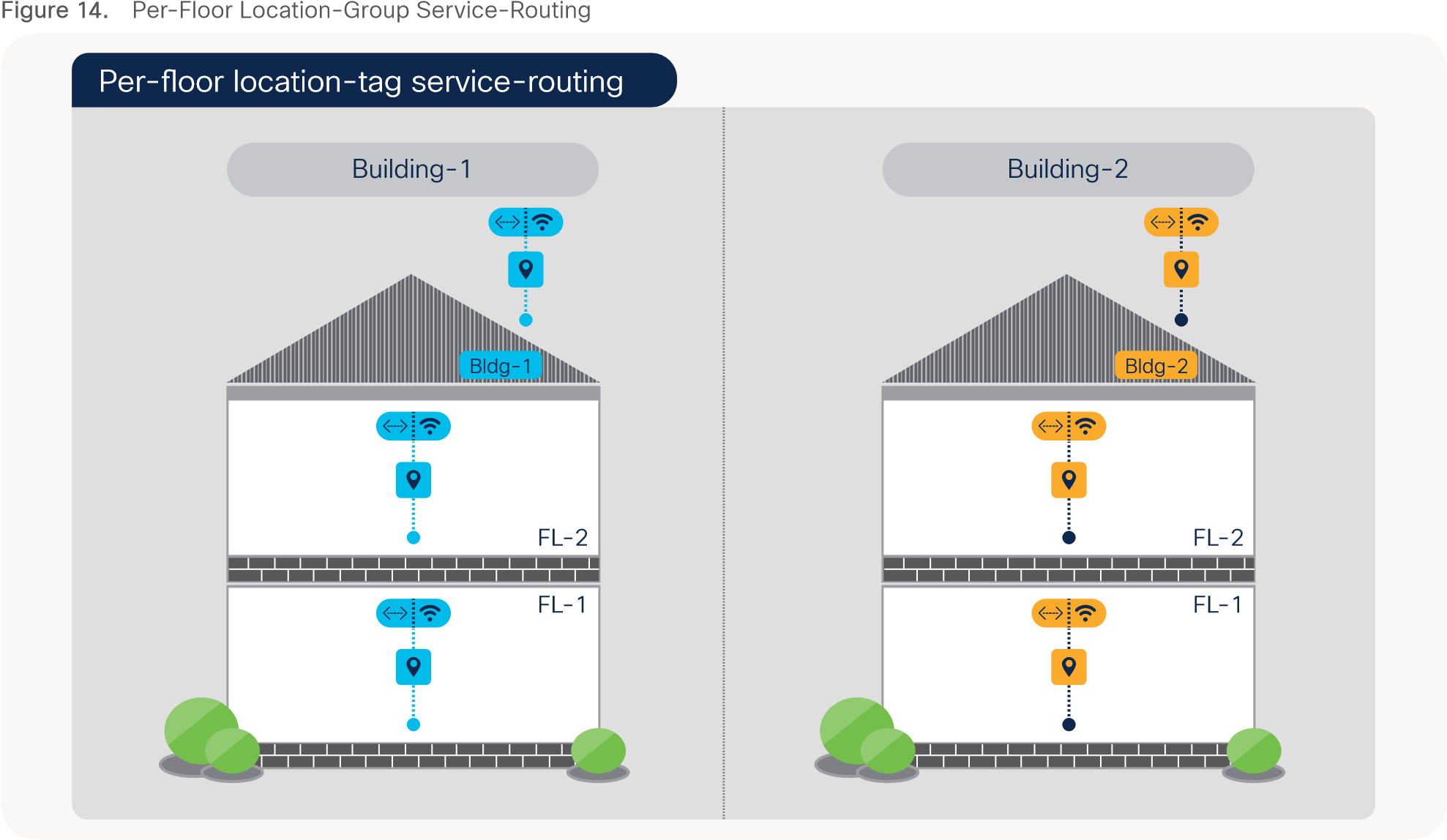
Per-Floor Location-Group Service-Routing
Table 9. Per-Floor Location-Group Service-Routing Plan
|
|
Building – 1 |
Building – 2 |
| Floor – 1 Group |
LAN Switch IP: 10.1.1.1 – 2 Regex AP Name: B1-FL1 |
LAN Switch IP: 10.1.1.5 – 6 Regex AP Name: B2-FL1 |
| Floor – 2 Group |
LAN Switch IP: 10.1.1.3 – 4 Regex AP Name: B1-FL2 |
LAN Switch IP: 10.1.1.7 – 8 Regex AP Name: B2-FL2 |
| WLC Management IP |
10.1.1.10 |
|
Table 10. Wide Area Bonjour – Per-Floor Location-Group Service-Routing Configuration
| LAN Access |
LAN Distribution |
WLAN Distribution |
WLC |
| Service-Peer |
Agent |
Agent |
Service-Peer |
| Step – 1: Default Mode – mDNS Service-Routing |
|||
| ! ! |
|||
| Step – 2: Custom Mode – Catalyst 9800 WLC mDNS Service-Policy |
|||
|
|
|
|
! mdns-sd service-list LOCAL-AREA-SERVICES-IN IN match printer … ! mdns-sd service-list LOCAL-AREA-SERVICES-OUT OUT match printer … ! mdns-sd service-policy LOCAL-AREA-SERVICE-POLICY service-list LOCAL-AREA-SERVICES-IN IN service-list LOCAL-AREA-SERVICES-OUT OUT ! wireless profile policy WLAN-PROFILE mdns-sd service-policy LOCAL-AREA-SERVICE-POLICY ! |
| Step – 3: Per-Floor – Enable Location-Group based Service-Routing |
|||
| ! Default Location-Group (0) on LAN switchport. No configuration required. |
! mdns-sd service-peer group ! Create Bldg-1 Service Peer-Group for per-Floor LAN Switch peer-group 1 service-policy default-mdns-service-policy service-peer 10.1.1.1 location-group default service-peer 10.1.1.2 location-group default ! … peer-group 3 ! Create Bldg-2 Service Peer-Group for per-Floor LAN Switch service-policy default-mdns-service-policy service-peer 10.1.1.5 location-group default service-peer 10.1.1.6 location-group default ! |
! Optional. Configure Inter Service-Peer service-routing if more than one WLC attached. |
! ! Create Bldg-1 FL-1 mDNS AP Group … rule-priority 3 rule-name Bldg-2-FL1-mDNS ! Create Bldg-2 FL-1 mDNS AP Group location location-group |
| Step – 4: Enable based Wide Area Bonjour Policy on Cisco DNAC |
|||
| Refer to Deploying Wide Area Bonjour Application Section to implement Bonjour Policy on Cisco DNA-Center. |
|||
Per-Zone Location-Group Configuration
The per-floor based mDNS service-routing boundary can be further sub-divided into logical services zones to enable deep granular and close-proximity based user-experience. The IT administrator can create logical services zones based on building floorplans, each individual service zones can match installed LAN switchports and Wireless Access-Points in the area. The mDNS Location-Group tags can be assigned to individual or group of Ethernet ports of LAN Access switches and combined with Wireless Access-Points providing WiFi services in same location of Ethernet connections.
The zone-based service-routing extends the key mobility and security benefits from building or floor level supporting close-proximity and secure service-routing solution to allow or dis-allow service service-routing based on their physical presence in specific IT defined service zones of a building floor.
The network administrator can group one or more Ethernet ports of LAN Access switches and assign Location-Group tag. Similarly, the Wireless Access-Points deployed on targeted service zones can be tagged providing WiFi services. In Wide Area Bonjour domain, the Cisco Catalyst 9000 series switches in distribution-layer can group one or more Service-Peers such as Layer 2 LAN Access switches and WLAN distribution switch can group one or more Catalyst 9800 WLC to support Location-Group based service-routing on per-zone basis.
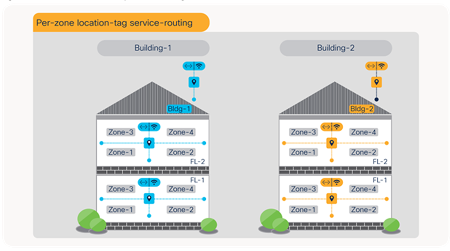
Per-Zone Location-Group Service-Routing
Table 11. Wide Area Bonjour – Per-Zone Location-Group Service-Routing Plan
|
|
Building – 1 |
Building – 2 |
| FL1 – Zone – 1 |
LAN Switch IP: 10.1.1.1 mDNS LAN Port : 1 – 10 Regex AP Name: B1-FL1-AP-[1-5] |
LAN Switch IP: 10.1.1.5 mDNS LAN Port : 1 – 10 Regex AP Name: B2-FL1-AP-[1-5] |
| FL1 – Zone – 2 |
LAN Switch IP: 10.1.1.1 mDNS LAN Port : 11 – 20 Regex AP Name: B1-FL1-AP-[6-10] |
LAN Switch IP: 10.1.1.5 mDNS LAN Port : 11 – 20 Regex AP Name: B2-FL1-AP-[6-10] |
| WLC Management IP |
10.1.1.10 |
|
Table 12. Wide Area Bonjour – Per-Zone Location-Tag Service-Routing Configuration
| LAN-Access |
LAN Distribution |
WLAN Distribution |
WLC |
| Service-Peer |
Agent |
Agent |
Service-Peer |
| Step – 1: Default Mode – mDNS Service-Routing |
|||
| ! ! |
|||
| Step – 2: Custom Mode – Catalyst 9800 WLC mDNS Service-Policy |
|||
|
|
|
|
! mdns-sd service-list LOCAL-AREA-SERVICES-IN IN match printer … ! mdns-sd service-list LOCAL-AREA-SERVICES-OUT OUT match printer … ! mdns-sd service-policy LOCAL-AREA-SERVICE-POLICY service-list LOCAL-AREA-SERVICES-IN IN service-list LOCAL-AREA-SERVICES-OUT OUT ! wireless profile policy WLAN-PROFILE mdns-sd service-policy LOCAL-AREA-SERVICE-POLICY ! |
| Step – 3: Per-Zone – Enable Location-Group based Service-Routing |
|||
| ! LAN Access – 10.1.1.1 ! interface Gi1/0/1 … interface Gi1/0/10 ! ! LAN Access – 10.1.1.2 ! interface Gi1/0/1 … interface Gi1/0/10 !
|
|
! Optional. Configure Inter Service-Peer service-routing if more than one WLC attached. |
! ! Create Bldg-1 FL-1 Zone-1 mDNS AP Group rule-priority 2 rule-name Bldg-1-FL1-Z2-mDNS ! Create Bldg-1 FL-1 Zone-2 mDNS AP Group … location location-group |
| Step – 4: Enable based Wide Area Bonjour Policy on Cisco DNAC |
|||
| Refer to Deploying Wide Area Bonjour Application Section to implement Bonjour Policy on Cisco DNA-Center. |
|||
Deploying Wide Area Bonjour Application
The Cisco Wide Area Bonjour application is add-on service in Cisco DNA-Center that enables the Bonjour Controller function to be paired with network-wide distributed and managed Cisco Catalyst 9000 series switches in SDG-Agent mode. The Cisco Wide Area Bonjour supports building stateful service-routing peering with network-wide SDG-Agents and provides broad-level of assurance capabilities to manage and monitor Bonjour services throughout the Wide Area Bonjour domain. This sub-section provides guidelines on deploying, managing, and monitoring the Bonjour services in Wide Area Bonjour domain from the Cisco DNA-Center.
Cisco Wide Area Bonjour Application Pre-Requisite
The network administrator must follow pre-requisites procedure to complete the requirements of Wide Area Bonjour prior implementing the network-wide service-routing. Figure – 16 below illustrates three simple step-by-step process to complete prior start using Cisco Wide Area Bonjour application:
● Install Application – The Cisco Wide Area Bonjour is non-default application of Cisco DNA-Center. The network administrator must download and install from catalog server.
● Software and License – The minimum software version Cisco IOS-XE 17.6.2 and network devices with DNA-Advantage license is required to implement capabilities described in this guide.
● Cisco DNA-Center – Ensure all mDNS gateway Ethernet switches and Catalyst 9800 WLC is added in Cisco DNA-Center inventory with appropriate credentials. Ensure all the devices have IP connectivity and successfully reached to Managed state.
After successful application installation the Cisco Wide Area Bonjour application can be found under Tools section. Figure – 16 below illustrates application icon for the Cisco Wide Area Bonjour application:
Cisco Wide Area Bonjour application
The Cisco Wide Area Bonjour application in Cisco DNA-Center is standalone application is not fully integrated with all other applications and tools of Cisco DNA-Center such as Site and Building Hierarchy, Topology etc. In future the application enhancements will enable unified service function following common principles as all other Cisco DNA-Center applications.
Configuring Cisco Wide Area Bonjour Service Domains
The Cisco Wide Area Bonjour application supports logical service domain constructs that can be used for building hierarchical global service-routing policies. The domain consists of following two simple structure levels that network administrator must create prior start building global service-routing policy to discover the mDNS service from one or more source and route to receiver or querying SDG-Agent across Wide Area Bonjour domain network.
Root Domain
The service root domain is first initial step to build policy hierarchy in Cisco Wide Area Bonjour application. The Root domain holds complete logical grouping of policies, service-cache database, service assurance and more. In this initial application configuration step, the network administrator can create Root domain with any user-defined name, i.e., ABC-Corp representing the organization name. Figure – 17 below illustrates initial domain configuration step to configure Cisco Wide Area Bonjour application.
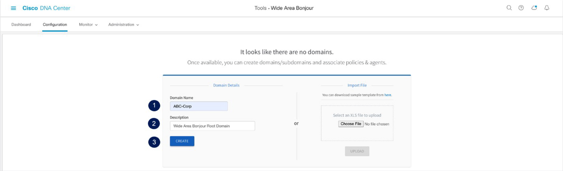
Cisco Wide Area Bonjour Application Root Domain Configuration
Sub-Domain
The sub-domain is logical and flexible structure of building service filters for Wide Area Bonjour. The network administrator can create one or more sub-domain with parent Root domain, for example two new sub-domains can be created under ABC-Corp domain. Each sub-domain can be uniquely labelled as Bldg-1 and Bldg-2 that aligns building structure plan of ABC-Corp organization.
The network administrator can create additional sub-domain for different floor-plans to each parent sub-domain enabling complete building hierarchy. Table – 13 below provides step-by-step reference guidance to build sub-domain configuration hierarchy under the Root domain:
Table 13. Cisco Wide Area Bonjour Sub-Domain Configuration Task
| Step |
Task |
Procedure |
| Step-1 |
Select Root domain |
Click to select ABC-Corp from left-panel |
| Step-2 |
Create first-tier sub-domains to the Root domain. |
Click to add new sub-domain, i.e., Bldg-1 and click Create button |
| Step-3 |
Select sub-domain from domain-list in left-panel. |
Click to select Bldg-1 from left-panel. |
| Step-4 |
Create second-tier sub-domains. |
Click to add new sub- domain, i.e., Bldg-1-FL1 and click Create button |
Figure – 18 below illustrates reference diagram of Wide Area Bonjour domain and sub-domain hierarchy in the application as initial step configuration.
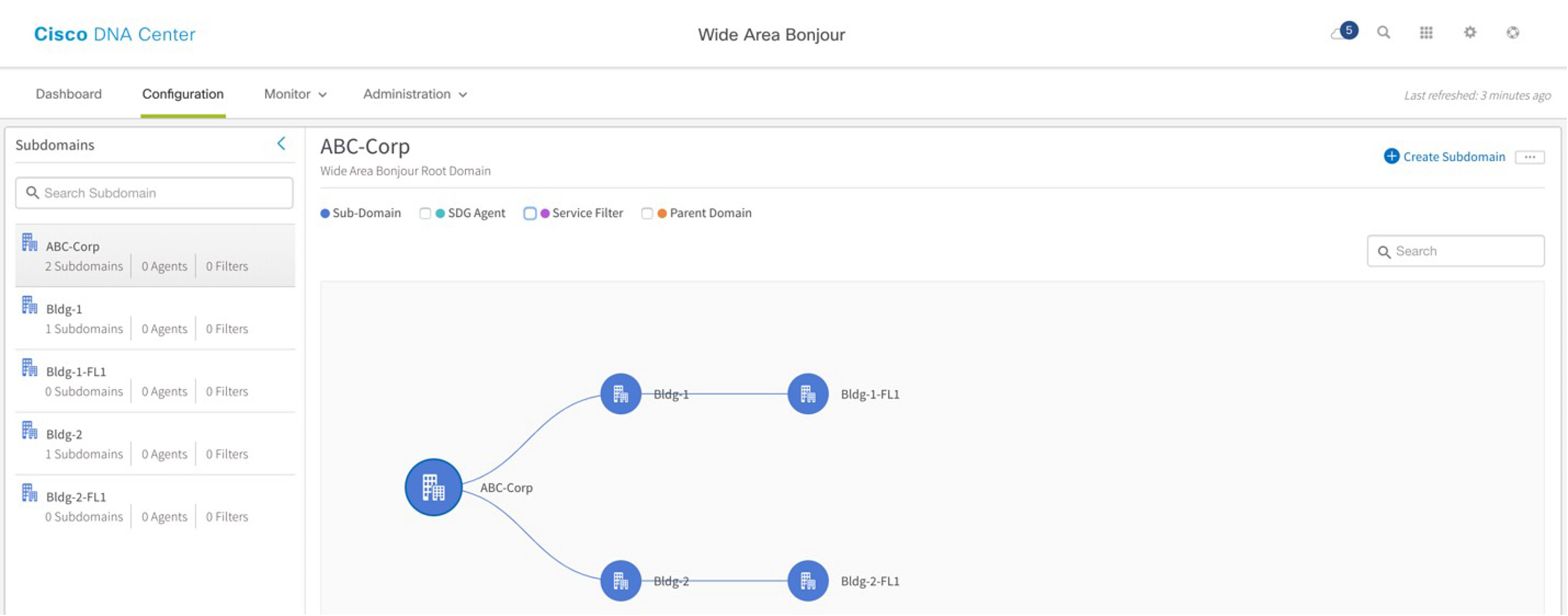
Cisco Wide Area Bonjour Application Sub-Domain Hierarchy
In summary, the notion of domain structure and hierarchy in Cisco Wide Area Bonjour application is to provide network administrator a flexible configuration and assurance capabilities to build site and network hierarchy where they would like to build and manage global service-routing policies.
Configuring Cisco Wide Area Bonjour Policy
The global service-routing structure in Cisco Wide Area Bonjour application provides flexibility to enable service-routing from any-to-any in large scale environment. The service announcement or service query request must pass implemented all policy for Cisco Wide Area Bonjour application to accept the service provider information to transmit to requesting SDG-Agent. Prior building the global policy on Cisco DNA-Center, the network administrator must understand end-to-end network environment and service-type to be activated on targeted Wired and Wireless networks.
This guide will provide reference configuration based on simple traditional Wired and Wireless Local mode environment as illustrated in following Figure – 19. The intent of configuring policy on Cisco DNA-Center is to enable Wired Printer discovery across IP core to the Wireless Apple iPad user. In addition, the service discovery shall be based on specific Location-Group as described in Deploying Location-Group Based Service-Routing section.
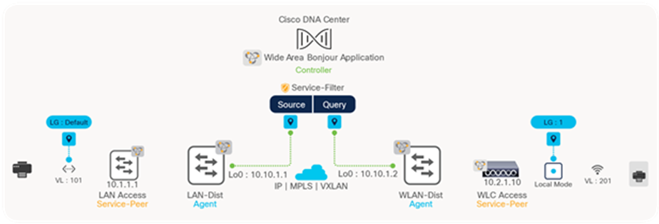
Cisco Wide Area Bonjour Policy Reference Network Design
Service-Filter
The Service-Filter is a global service-routing policy that can be created at any level of the domain in Cisco Wide Area Bonjour application. The simplified policy structure allows network administrator to configure basic parameters and SDG-Agents in specific role and network information to enable service-routing. Table – 14 below provides configuration guidelines to create new service-filter to enable Bonjour service discovery from wired SDG-Agent and distribution to another wireless SDG-Agent switch:
Table 14. Cisco Wide Area Bonjour Service-Filter Navigation
| Task |
Step |
| Select sub-domain domain. |
Click sub-domain from left-panel, i.e., Bldg-1-FL1 |
| Select Service Filter from the configuration panel to expand the policy-panel. |
Click to select the sub-domain and click the Service-Filter |
| Create new Service Filter. |
Click |
The intuitive and flexible configuration service-filter supports various service-routing topologies using single service-filter policy. It is imperative to understand the constructs and function of service-filter to enable service discovery and distribution from distributed SDG-Agent, downstream Service-Peer devices, and network details to construct the policy. Figure – 20 below illustrates and reference service-filter configuration to implement Source SDG Agent service-routing for network requirements as illustrated above in Figure – 19 under selected sub-domain:
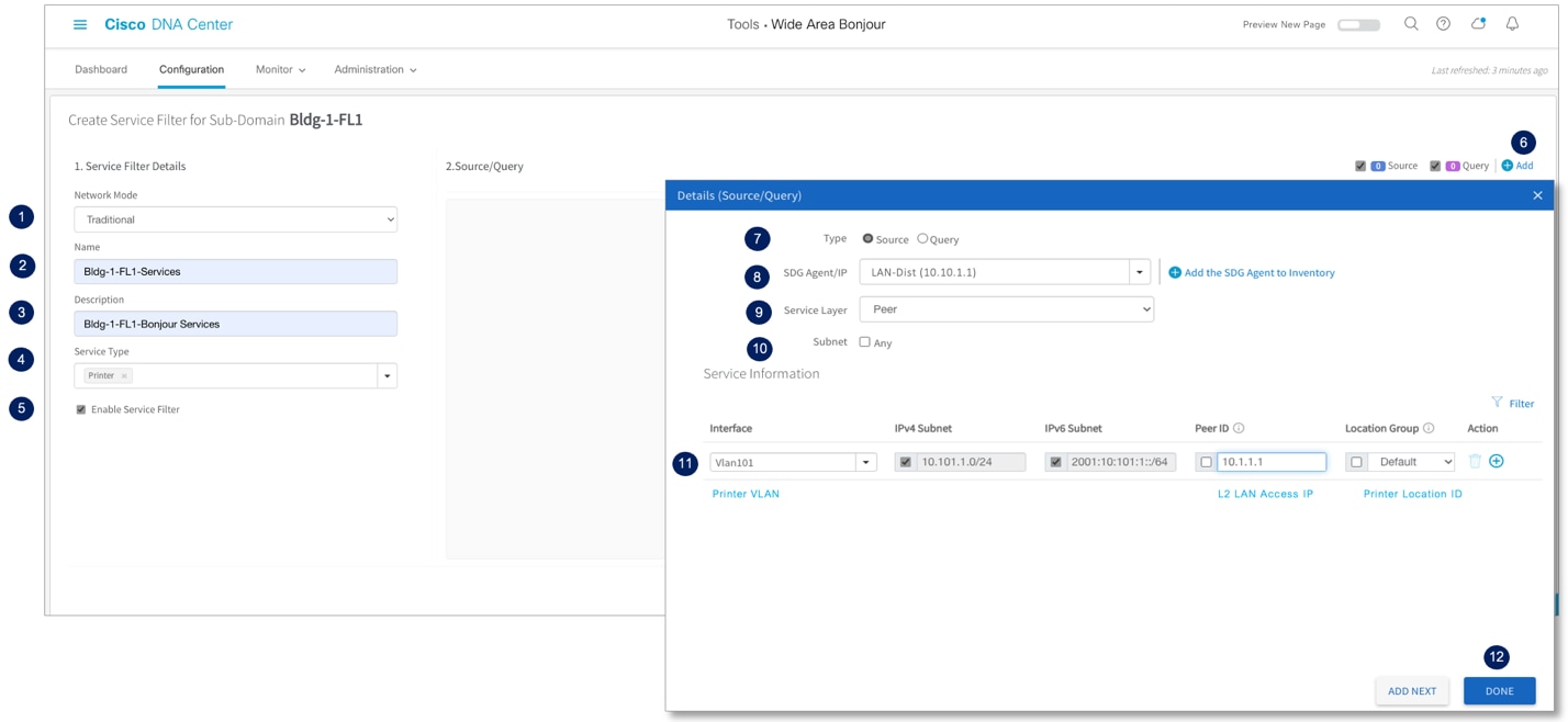
Cisco Wide Area Bonjour Service Filter – Source SDG Agent
The Wide Area Bonjour Service Filter consists of two-side SDG-Agent and respective configurations – Source and Query. The Source SDG-Agent advertises mDNS services to Cisco DNA-Center, whereas the Query SDG-Agent sends mDNS service lookup request to Cisco DNA-Center. Table – 15 below provides step-by-step configuration task to build Source SDG-Agent service filter on selected sub-domain of application.
Table 15. Cisco Wide Area Bonjour Source SDG Agent Service Filter Configuration Task
| Step |
Task |
Procedure |
| Step-1 |
Select Network Mode |
Select Traditional Network Mode. Default. |
| Step-2 |
Create new service-filter |
Create new unique service-filter name, i.e., Bldg-1-FL1-SERVICES |
| Step-3 |
Description |
Optional. Enter Service Filter description. |
| Step-4 |
Select Wide Area Bonjour services |
Click drop-down menu to select Printer for this service-filter. Create custom service from Administration ➜ Service-Type for additional services. |
| Step-5 |
Enable service-filter in Cisco Wide Area Bonjour domain |
Click Uncheck to allow service-filter configuration but disable processing. Default is enabled. |
| Step-6 |
Add Source SDG-Agent to service-filter |
Click |
| Step-7 |
Select Type as Source |
Click WLAN networks to Cisco DNA-Center. |
| Step-8 |
Select Source SDG Agent Device |
Select Source SDG Agent Catalyst switch from drop-down menu, i.e., LAN Agent 10.10.1.1. |
| Step-9 |
Select Service Layer Mode |
Two available Service Layer mode: Local – Select if mDNS endpoint is directly attached to SDG Agent switch, i.e., Layer 3 mode Access. Peer – Select if mDNS endpoint is indirectly attached to SDG Agent switch and it is learning or receiving service request from downstream Layer 2 Service-Peer, i.e., LAN Access switch or Cisco 9800 WLC. |
| Step-10 |
Source SDG Agent Any Subnet Filtering |
Optional. Click checkbox to permit accept mDNS messages from source SDG-Agent originated from IPv4/IPv6 network, Service-Peer ID and Location-Tag. |
| Step-11 |
Source SDG Agent Selective Subnet Filtering |
Select Interface VLAN ID matching mDNS policy. Enter downstream Service-Peer IP address, i.e., 10.1.1.1, for Layer 2 LAN Access Switch 1. Select Default from Location-Group if no location-ID assigned on Ethernet switchport. |
| Step-12 |
Complete Source SDG Agent configuration |
Click Done button to complete Source SDG Agent side configuration. |
To complete service-filter the receiver or Query side WLAN-Dist SDG Agent configuration must be configured enabling end-to-end service-routing between Wired and Wireless networks. Figure – 21 below illustrates and reference service-filter configuration to implement Query SDG Agent service-routing for network requirements as illustrated above in Figure – 19 under selected sub-domain:
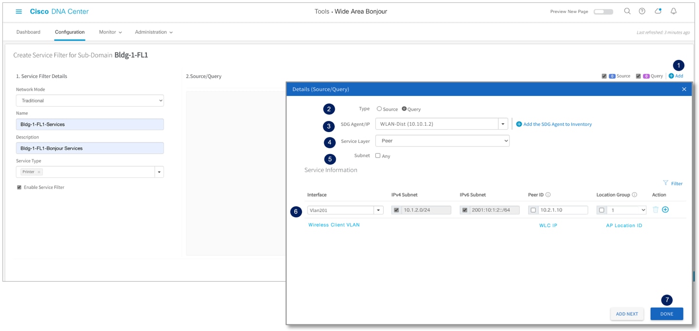
Cisco Wide Area Bonjour Service Filter – Query SDG Agent
Table – 16 below provides step-by-step configuration task to build Query SDG-Agent service filter on selected sub-domain of application.
Table 16. Cisco Wide Area Bonjour Query SDG Agent Service Filter Configuration Task
| Step |
Task |
Step |
| Step-1 |
Add Query SDG-Agent to the service-filter |
Click |
| Step-2 |
Select Type as Query |
Click button to select SDG-Agent advertising mDNS service from LAN or WLAN networks to Cisco DNA-Center. For example, WLAN Agent-2 10.10.1.2 |
| Step-3 |
Select Service Layer Mode |
Two available Service Layer mode: Local – Select if mDNS endpoint is directly attached to SDG Agent switch, i.e., Layer 3 mode Access. Peer – Select if mDNS endpoint is indirectly attached to SDG Agent switch and it is learning or receiving service request from downstream Layer 2 Service-Peer, i.e., LAN Access switch or Cisco 9800 WLC. |
| Step-4 |
Query SDG Agent Any Subnet Filtering |
Optional. Click checkbox to permit accept mDNS messages from query SDG-Agent originated from IPv4/IPv6 network, Service-Peer ID and Location-Tag. |
| Step-5 |
Query SDG Agent Selective Subnet Filtering |
Select Interface VLAN ID matching mDNS policy, i.e., Wireless Client VLAN ID. Enter downstream Service-Peer IP address, i.e., 10.2.1.10, for WLC. Select Custom from Location-Group and enter Location ID i.e., 1 assigned to Bldg-1 mDNS AP group. Else, select Default (0). |
| Step-6 |
Complete Query SDG Agent configuration |
Click Done button to complete Query SDG Agent side configuration. |
| Step-7 |
Complete configuring Service Filter |
Click Create button to create Wide Area Bonjour global service-routing policy. |
Configuring Cisco Wide Area Bonjour Service-List
The Bonjour service-provider may provide one or more types of sub-services, such as single multifunction printer, i.e., Printer name Bldg-1-PRN may advertise Print, Mobile Print, Scan, Fax, and more sub-services in the network. Each of these sub-services are announced in form of mDNS PoinTeR (PTR) records that needs to be part of policy in Local Area and Wide Area Bonjour domain to permit service discovery and distribution in the global network. The Cisco Wide Area Bonjour application supports built-in Service-List for commonly found Bonjour services in the network. By default, the application pairs the common type of PTR enabling sub-services in the network.
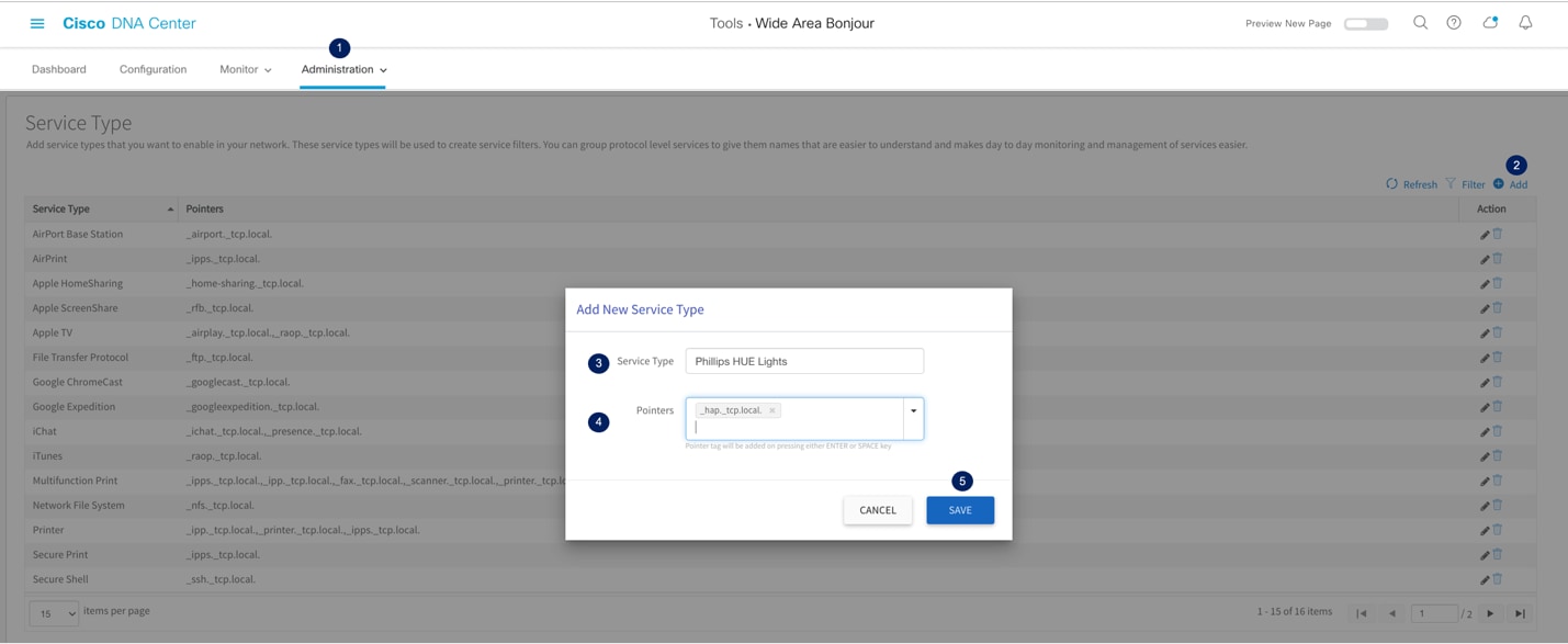
The network administrator can leverage the default service-list or create custom entry to enable new services across Wide Area Bonjour domain network. The mDNS PTR records are simple in regular-expression format that each endpoint supports with unique record name for specific services. The service name and transport protocol port numbers that may be IANA registered or unregistered. The network administrator must identify the custom PTR record from manufacturer guide or use service scanner tools to discover running custom service PTRs from targeted network segments prior creating custom entries. Figure – 22 below illustrates reference diagram in creating custom service-list entry Cisco DNA-Center:
Cisco Wide Area Bonjour Custom Service-List
Table – 17 below provides step-by-step configuration task to create new custom service-list entry in Cisco Wide Area Bonjour application.
Table 17. Cisco Wide Area Bonjour Custom Service Type Configuration
| Task |
Step |
| Go to Administration section. |
Click Administration ➜ Service-Type and click
|
| Add service-list name and record(s). |
Add new and unique Service Type name, i.e., Phillips HUE Light. In Pointers section add mDNS PTR record for this service, i.e., _hap._tcp.local. It is important to end each PTR with “.” and press Return or Enter to create new entry. For multiple PTR records add comma (,) as de-limiter between two records. |
| Save custom service-list. |
Click Save button to save custom service-list in application database. |
Cisco Wide Area Bonjour Application Assurance
To manage, monitor and troubleshoot the Wide Area Bonjour domain for the day-n operation the Cisco Wide Area Bonjour application supports various level of integrated service assurance capabilities. The network administrator can monitor network-wide activities at various levels ranging from services and SDG-Agent statistics, per sub-domain level services count and validating the agents and policy operational status. The end-to-end service-routing detail in Wide Area Bonjour can be monitored on per-instance level providing granular details from origination point, advertising SDG-Agent, domain policy and much more.
This sub-section focuses on providing operational details around four different types of Cisco Wide Area Bonjour application assurance capabilities – Dashboard, Sub-Domain 3600, Detail View, and Troubleshooting.
Dashboard
The Cisco Wide Area Bonjour dashboard provide real-time aggregated information about services counts and states visibility combined with top talkers across the Wide Area Bonjour domain. From this startup-screen of Wide Area Bonjour application the network administrator can verify the overall health of Wide Area Bonjour domain with SDG-Agent device reachability, service-routing status and Query statistics in real-time to identify next steps to resolve if any challenge. Figure – 23 below illustrates a reference view of Cisco Wide Area Bonjour application dashboard screen.
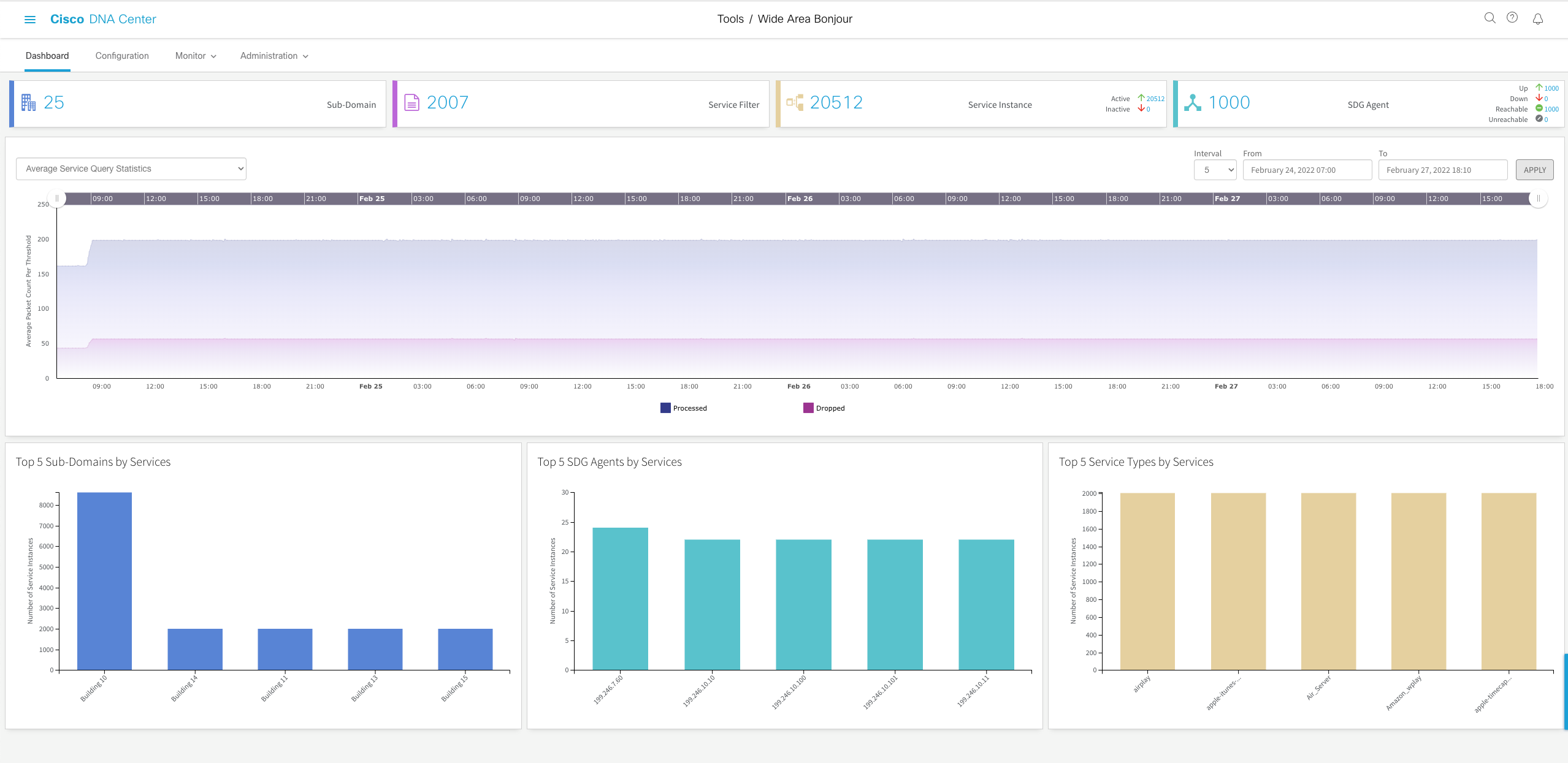
Cisco Wide Area Bonjour Application Dashboard
The Dashboard view is divided in following three major assurance categories:
● Network Dashlet – The Network Dashlet is top view of Dashboard screen providing aggregated statistics of overall sub-domain, SDG-Agent, and services.
● Global Query Statistic – A line graph with time history that provides chart view of Wide Area Bonjour service discovery requests to Cisco DNA-Center from remote SDG-Agent devices.
● Top-Talker – The Top-5 talkers in the network providing quick scale overview of top sub-domains, SDG-Agents with high services and service types in the network.
Sub-Domain 3600
The network administrator can get 3600 statistics view of Sub-Domain and associated parameters from the Configuration tab. The key objective of 3600 statistics is to provide brief information at individual sub-domain basis instead global level visualization on Dashboard. The Sub-Domain 3600 gives an ability to navigate the different levels of hierarchical domain structure and verify the aggregated statistics for policy configuration, service-instance count and much more.
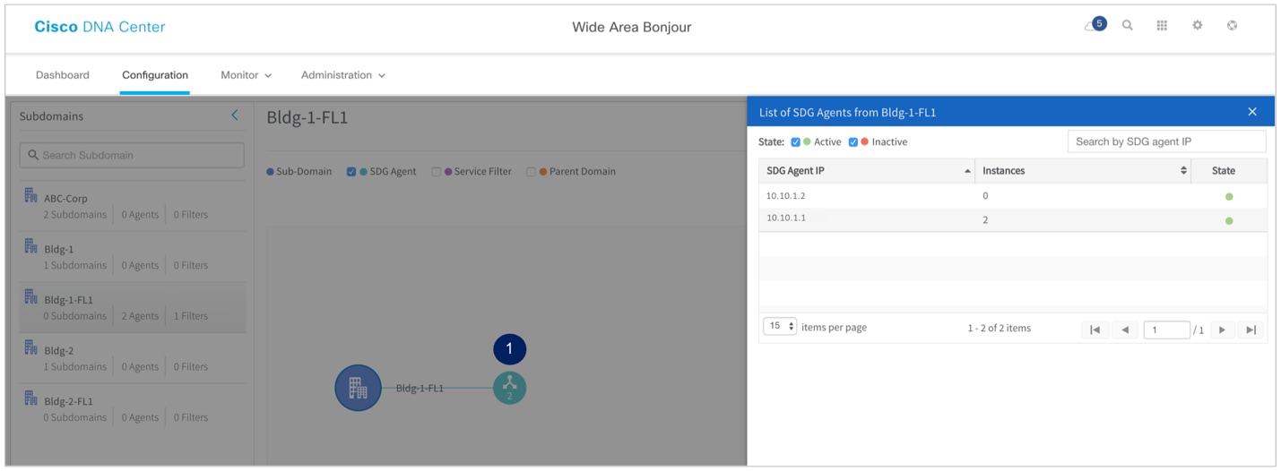
The Sub-Domain 3600 view can be grouped in two-level parameters comprising Policy and SDG-Agent of selected Sub-Domain. Figure – 24 below illustrates a reference Sub-Domain 3600 view of SDG-Agent statistics:
Sub-Domain 3600 Sub-Agent Statistics
Table 18. Cisco Wide Area Bonjour Sub-Domain 3600 Sub-Agent Statistics
| Task |
Step |
| Select Sub-Domain from Left-Panel. |
Select Sub-Domain to open 3600 statistics view. |
| Select SDG Agent. |
Click checkbox for SDG Agent to expand selected sub-domain hierarchy providing aggregated SDG-Agent count information. |
| Expand SDG Agent Information. |
Click
button to open 3600 view of each SDG-Agent of select Sub-Domain. |
| Verify SDG Agent 3600 Status. |
Verify three key indicators of one or more SDG Agents from selected Sub-Domain:
●
SDG Agent IP – An IP address of SDG-Agent selected based on service-filter policy configuration.
●
Instances – Aggregated count of Bonjour services discovered from each source SDG-Agent network device.
●
State – The service-routing state between Cisco DNA-Center and SDG-Agent device. In normal up and operational state it shows Green, else Red color when peering is down.
|
The Service-Filter 3600 provides two key options for network administrator to build and manage the global policies. The network administrator can select SDG-Agent and Service-Filter to view or create new Service-Filter on selected Sub-Domain. Figure – 25 below illustrates a reference Sub-Domain 3600 view of Service-Filter statistics:
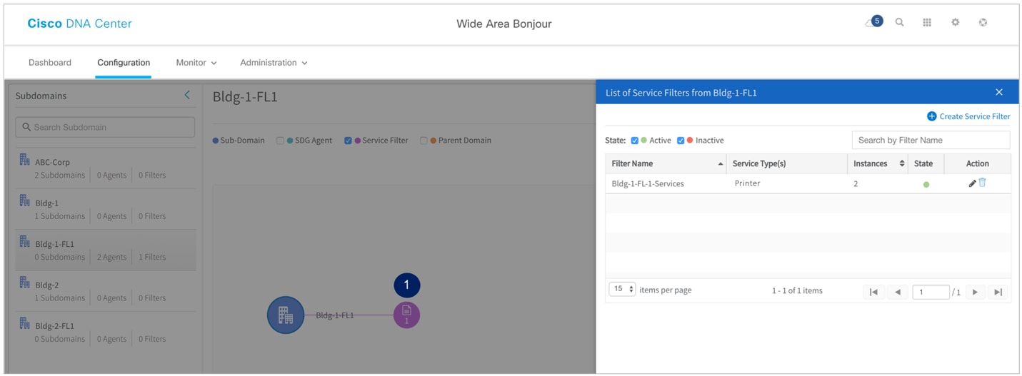
Sub-Domain 3600 Service-Filter Statistics
Table 19. Cisco Wide Area Bonjour Sub-Domain 3600 Service-Filter Statistics
| Task |
Step |
| Select Sub-Domain from Left-Panel. |
Search or select Sub-Domain to view 3600 statistics |
| Select Service-Filter. |
Click checkbox for Service Filter to expand selected sub-domain hierarchy providing aggregated Service Filter count information. |
| Expand SDG Agent Information. |
Click
button to open 3600 views of each Service-Filter of select Sub-Domain. |
| Verify SDG Agent 3600 Status. |
Verify five key indicators of one or more Service-Filter from selected Sub-Domain:
●
Filter Name – Admin created global Service-Filter on selected sub-domain
●
Service-Type(s) – Types of Bonjour service(s) permitted allowed for global discovery and distribution
●
Instances – Total aggregated service-instance count discovered from one or more source SDG-Agents on each Service-Filter
●
State – Service-Filter in Active state enables service-routing peering, service discovery and distribution between all SDG-Agents. If Inactive state it disables service-routing between all SDG-Agents part of this Service-Filter.
●
Action – The network administrator can Edit or Delete the selected Service-Filter.
|
Detail View
The Cisco Wide Area Bonjour application supports detail monitoring and service-routing status from the Monitor tab. The detail view can also provide abilities to troubleshoot if there are service-routing issues at individual service-instance level or an SDG-Agent level. The Monitor section is sub-divided in following categories:
● SDG-Agent Detail – This page provides detail information to understand the configuration, statistics, and status of each SDG-Agent. In addition, the network administrator can select one or more source SDG-Agent to manually force service cache resynchronization to update global information in Cisco DNA-Center.
● Service-Instance Detail – This page provides details information of each Bonjour service-instance information and their routing status can be verified.
Figure – 26 below illustrates a reference detail view of SDG-Agent listing and various associated parameters to each network devices
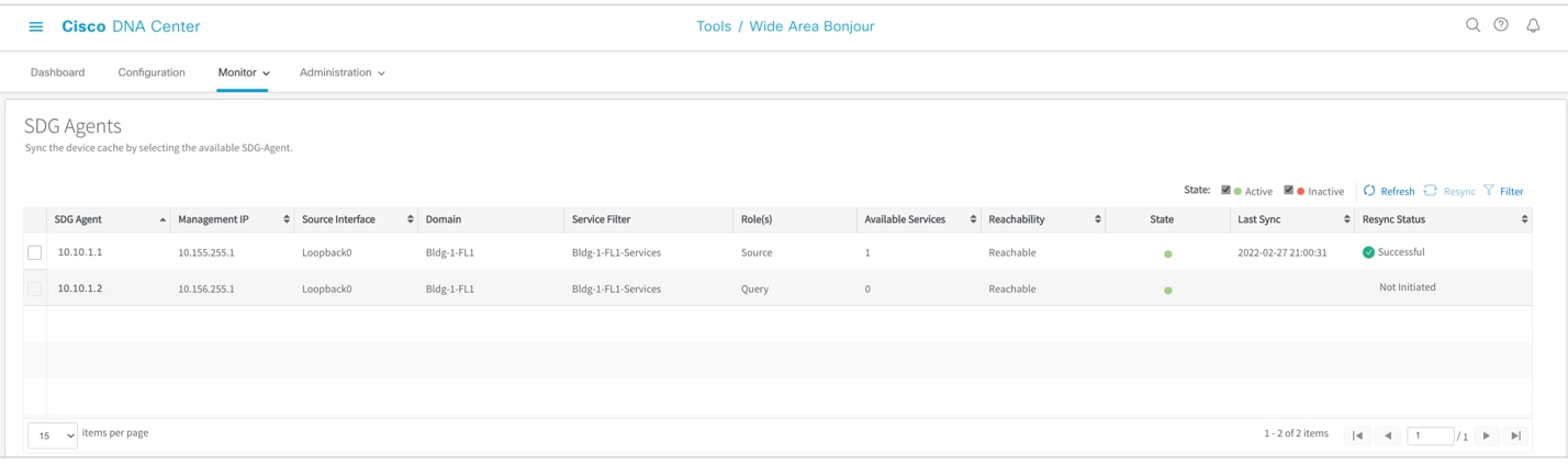
Monitoring SDG-Agent Detail
Table 20. Cisco Wide Area Bonjour SDG-Agent Monitoring
| Task |
Step |
| Go to Detail SDG Agent Monitoring. |
Click Monitor Tab ➜ and select SDG Agents from sub-menu. |
| Optional. Manual Services resynchronization in Wide Area Bonjour domain. |
Click checkbox to select one or more SDG-Agents and click |
| Verify SDG-Agent Detail Status. |
The SDG-Agent detail page provides multiple key indicators pertaining to configuration and operational state:
●
SDG Agent – List of SDG-Agent part of one or more Service-Filter policy configuration.
●
Management IP – An SDG Agent IP address use to manage the network device.
●
Source Interface – An SDG Agent IP address use to establish service-routing session.
●
Domain – Name of one or more sub-domain where each SDG-Agents are associated.
●
Service-Filter – Name of one or more Service-Filter where each SDG-Agents are associated.
●
Role(s) – The SDG-Agent can be in Source role advertising services to Cisco DNA-Center or Query role requesting services from Cisco DNA-Center. In bi-directional scenario the same SDG-Agent are in Source and Query roles.
●
Service-Filter – Name of one or more Service-Filter where each SDG-Agents are associated with policy.
●
Available Services(s) – Total service-instance count received from each source SDG-Agent.
●
Reachability – SDG-Agent network reachability and SNMP manageability status.
●
State – Service-routing peering status between Cisco DNA-Center and each SDG-Agent.
●
Last Sync – Timestamp of services synchronization between Cisco DNA-Center and source SDG-Agent.
●
Resync Status – Manual service-instance resynchronization status.
|
Figure – 27 below illustrates a reference detail view of mDNS Service-Instance listing and various associated network and policy parameters to discovered from various source SDG-Agent based on service-filter policy configuration:
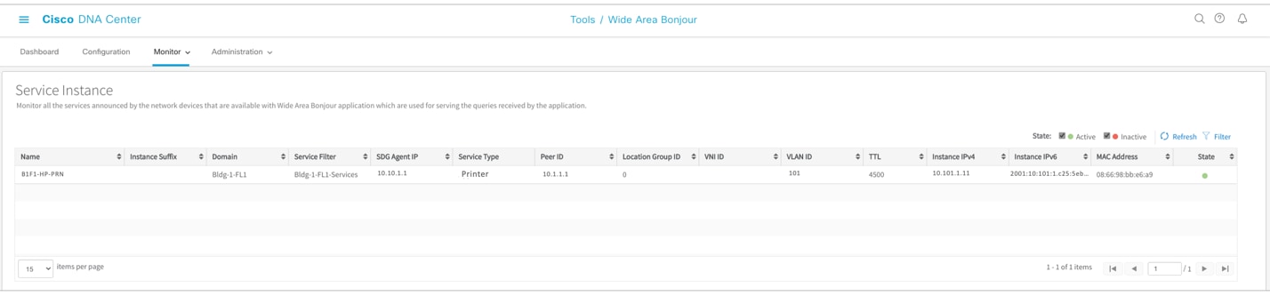
Monitoring Service-Instance Detail
Table 21. Cisco Wide Area Bonjour Application Service-Instance Monitoring
| Task |
Step |
| Go to Service-Instance section. |
Click Monitor Tab ➜ and select Service-Instance from sub-menu. |
| Verify Bonjour Service-Instance Detail Status. |
The Service-Instance page consist of status for each service-instance, origination point, policy, and reachability information in the Wide Area Bonjour domain:
●
Name – The mDNS service provider endpoint name.
●
Instance Suffix – Optional text-string appended to original service-instance name for any type of administrative purpose.
●
Domain(s) – Sub-Domain name from where service is discovered.
●
Service Filter(s) – Service-Filter Name that was verified and permitted to accept service from source SDG-Agent network device
●
SDG Agent IP – Source SDG-Agent advertised mDNS service(s)
●
Service Type(s) – mDNS service-type announced by provider.
●
Peer ID – Original source Service-Peer Switch/WLC IP address announced service to SDG Agent.
●
Location-Group ID – The Location-Group tag associated to mDNS service-provider LAN port or Wireless Access-Point.
●
VNI ID – The mDNS service provider mapped to overlay BGP EVPN VXLAN L2 or L3 network. The VNI ID is overlay virtual network ID.
●
VLAN ID – The Layer 2 VLAN ID mapped to Wired or Wireless mDNS service provider endpoint
●
TTL – Long-lived mDNS TTL value of 4500 sec remains intact across Wide Area Bonjour domain.
●
IPv4 Address – An IPv4 address (A record) of mDNS endpoints.
●
IPv6 Address – A globally routed IPv6 address (AAAA record) of mDNS endpoints.
●
MAC Address – Original Wired or Wireless MAC address of mDNS endpoints.
●
Status – The service-instance will be distributed to Querying SDG-Agent if state Active. The service-instance entries marked as Inactive will be prevented from global distribution if withdrawn from source SDG-Agent. The Inactive entries are automatically purged after 24 hours.
|
Cisco Wide Area Bonjour Application Administration
The administration section of Cisco Wide Area Bonjour application allows network administrator to build and manage global services parameters and policy configuration file management. The features in this section can be used during initial or any day-n deployment stage to complete regular network operation tasks. The network administrator can manage application service, database, and SDG-Agent global parameters from the Administration menu tab. The policy configuration management is flexible to manage importing or exporting at domain level hierarchy without causing any service-routing disruption or downtime.
This section is divided in multiple sub-sections focusing on different application administration capabilities that network administrator can use to manage the Wide Area Bonjour domain.
Global Parameters
The global parameters are common configuration set that is applied to all SDG-Agent paired with Cisco Wide Area Bonjour application. The network administrator can build secure the service peering communication with all SDG-Agent using MD5 authentication and can adjust default keepalive timer settings to maintain service peering. In Cisco Wide Area Bonjour architecture these service routing parameters are part of initial handshaking and set based on value configured in global settings.
As these global configuration parameters are centrally managed in control-plane from Cisco DNA-Center there are no relevant CLI automated to network devices. The network administrator change update such service-routing parameters that are dynamically adjusted without resetting existing peering session thus providing best-in-class service resiliency in the network. Figure – 28 below illustrates reference view of global parameters settings.
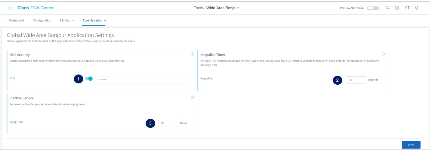
Cisco Wide Area Bonjour Global Parameters
Table 22. Cisco Wide Area Bonjour Global Parameter Configuration
| Task |
Step |
| Go to Global Parameter section. |
Click Administration Tab ➜ and select Global from sub-menu. |
| Secure SDG-Agent service peering sessions. |
Slide the button to enable MD5 authentication security between Cisco DNA-Center and SDG-Agent devices. |
| Adjust service peering timers. |
By default, the Hello message timer between Cisco DNA-Center and SDG-Agent is set to 30 seconds with four multiplier of 120 seconds dead-interval timer. The value can be adjusted between 15-120 seconds. |
| Inactive Service Maintenance. |
The Cisco DNA-Center holds inactive services information for up to 24 hours by default. The value can be adjusted between 1-24 hours. |
Service-Type Database
The Cisco DNA-Center supports built-in Service-Type database with user-friendly Bonjour service name paired minimum requirement mDNS PTR records to enable and use the services across Wide Area Bonjour domain. Like Cisco IOS-XE operating system, the Cisco DNA-Center Bonjour Service-Type database provides flexibility to create custom service entries if default values do not meet the requirements. Figure – 29 below illustrates reference view of Service-Type in Cisco Wide Area Bonjour application:
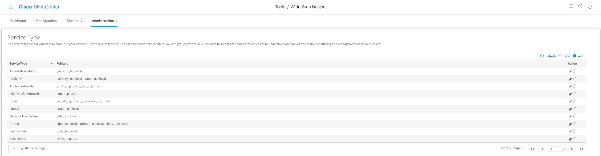
Cisco Wide Area Bonjour Application Service-Type Database
Table 23. Cisco Wide Area Bonjour Service-Type Configuration
| Task |
Step |
| Go to Service-Type section |
Click Administration Tab ➜ and select Service-Type from sub-menu. |
| Verify default built-in Service-Type |
The service-type table provide following two simple information:
● Service Type – System-defined and user-friendly name of mDNS service.
● Pointers – One or more mDNS PTR records for each service type.
|
Managing Policy Configuration
The Cisco Wide Area Bonjour application provides flexibility to build and manage service-filter policies manually or can be provisioned in bulk during any stage of deployment. Refer to Table – 9 Cisco Wide Area Bonjour Service Filter Configuration Task for step-by-step manual procedure to build the service-filter. This sub-section focuses on bulk policy provisioning and managing configuration files for backup.
The service-filter policy configuration template is built based on Microsoft Excel XLS format. The network administrator can download pre-built structured and formatted blank XLS template file from Cisco Wide Area Bonjour application. It can be downloaded during initial application provisioning stage of building Root Domain or export the XLS configuration from any level of domain hierarchy with up-to-date configuration. The XLS template file is divided in four different worksheets, each crosslink with required details to automate large scale service-filter policies. Figure – 30 below explains the brief overview of each worksheet that must be configured to build and provision bulk service-filter policies:
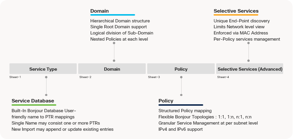
Cisco Wide Area Bonjour Policy Template
The Cisco Wide Area Bonjour XLS template file contains pre-defined column and respective names that must remain intact else importing the modified file may fail. The network administrator must feed required data on their respective column for each worksheet based on following reference configuration model. The Selective Services worksheet is optional and can be used in advanced service-routing scenarios where service distribution from Cisco DNA-Center must be limited to user-defined static MAC address basis. For example, Cisco DNA-Center discovered up to ten AirPrint capable printers with Selective Services support, the network administrator can statically assign MAC address of two printer to be responded from it receives query from receiver SDG-Agent.
Import/Export Policy Configuration
The Cisco Wide Area Bonjour application provides flexibility in managing bulk configuration with Import and Export capabilities. The application domain and policies can be built and imported as initial Day-0 configuration for bulk provision instead manual process. The existing policy configuration can be downloaded to local computer in XLS format to update existing policies and backup purpose.
The policy configuration import is seamless in operation and can be appended to Cisco Wide Area Bonjour application while it in operational state. The new imported file may include new service-types in database, additional services to existing policies or new sub-domains with new policies. During configuration import state the application and service-peering with existing SDG-Agents remains intact providing non-disruptive bulk provisioning capabilities to scale up network and services in Wide Area Bonjour domain. The network administrator can import configuration at any domain hierarchy of an application.
The export function downloads latest configuration snapshot from Cisco Wide Area Bonjour application to local computer. The downloaded file can be updated with new bulk changes and re-import to update the configuration. The network administrator can use export function as configuration backup to be restored as needed.
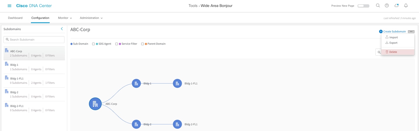
Cisco Wide Area Bonjour Application – Import/Export Policy Configuration
Table 24. Cisco Wide Area Bonjour Service-Type Configuration
| Task |
Step |
| Select Domain for Import/Export Configuration |
Click Configuration Tab ➜ and select Root or Sub-Domain from left panel to Import or Export the configuration. |
| Select Import or Export |
Click Import or Export to act on managing configuration file for select domain. |
Scale and Performance Support Matrix
The Cisco DNA Service for Bonjour solution is fully distributed mDNS service-routing solution hence it provides high scale solution for larg size Enterprise networks. Each product in overall solution scales differently due to different level of system resources.
Table 25. Cisco DNA-Center Wide Area Bonjour Scale and Performance Matrix
| Cisco DNA Center |
Service Scale |
Release |
| DN2-HW-APL DN2-HW-APL-L DN2-HW-APL-XL |
150,000 Services Scale 1000 SDG Agent |
Cisco DNA-Center – 2.2.3 Cisco Wide Area Bonjour Application |
Table 26. Cisco IOS-XE mDNS Scale and Performance Matrix
| Platform |
Mode |
Service Scale |
Release |
| Cisco Catalyst 9300 |
Service-Peer or Agent |
7500 |
17.6.2 |
| Cisco Catalyst 9400 |
Service-Peer or Agent |
10000 |
17.6.2 |
| Cisco Catalyst 9500 |
Service-Peer or Agent |
12000 |
17.6.2 |
| Cisco Catalyst 9500-H |
Service-Peer or Agent |
12000 |
17.6.2 |
| Cisco Catalyst 9600 |
Service-Peer or Agent |
15000 |
17.6.2 |
| Cisco Catalyst 9800-80 WLC |
Service-Peer |
14000 |
17.6.2 |
| Cisco Catalyst 9800-40 WLC |
Service-Peer |
12000 |
17.6.2 |
| Cisco Catalyst 9800-L WLC |
Service-Peer |
4000 |
17.6.2 |
| Cisco Catalyst 9800-CL WLC |
Service-Peer |
2000 |
17.6.2 |
Cisco DNA Service for Bonjour is enterprise-grade Wide Area Bonjour solution designed to seamlessly integrated into complex wired and wireless network infrastructure. The Cisco Wide Area Bonjour retains original end-users experience for using Bonjour technology in Enterprise. In addition, the new solution provides plug-n-play service-routing capabilities without any forklift changes in DHCP/DNS servers or manual MAC address management.
The new distributed architecture supports unparallel scale, performance, security, and redundancy that offers vendor agnostic compatible solution to enable end-to-end services rich network infrastructure between computers, IoT and more.
CCO Solution
Cisco DNA Service for Bonjour - Solution Landing Page
At-A-Glance
Cisco DNA Service for Bonjour Solution At-A-Glance
Cisco DNA Service for Bonjour Deployment Guide
Cisco DNA Service for Bonjour Deployment Guide – Traditional LAN and Wireless Local Mode
Cisco DNA Service for Bonjour Deployment Guide – Cisco Software-Defined Access Mode
Quick Configuration Guide
Cisco DNA Service for Bonjour Quick Configuration Guide
Cisco DNA Service for Bonjour CCO Configuration Guide
Cisco Catalyst 9300 Series Switches
Cisco Catalyst 9400 Series Switches
Cisco Catalyst 9500 Series Switches
Cisco Catalyst 9600 Series Switches
Cisco Catalyst 9800 Series WLC
Cisco Catalyst 9100 Series – Embedded Wireless LAN Controller
Cisco DNA-Center – Wide Area Bonjour User Guide