Cisco FlexConnect and EWC Bonjour Deployment Guide
Available Languages
Bias-Free Language
The documentation set for this product strives to use bias-free language. For the purposes of this documentation set, bias-free is defined as language that does not imply discrimination based on age, disability, gender, racial identity, ethnic identity, sexual orientation, socioeconomic status, and intersectionality. Exceptions may be present in the documentation due to language that is hardcoded in the user interfaces of the product software, language used based on RFP documentation, or language that is used by a referenced third-party product. Learn more about how Cisco is using Inclusive Language.
Bonjour technology invented and standardized by Apple introducing zero-configuration solution that simplifies network configuration and enables communication between connected devices, services, and applications. Bonjour leverages link-local Multicast DNS and it is designed to enable peer-to-peer communication on single Layer 2 domains that are ideal for small, flat, single-domain setups, such as home networks.
The mDNS enabled services on consumer products, digital conference room, IoT and more is pervasive in service-oriented Enterprise network. The Cisco DNA Service for Bonjour solution eliminates the single Layer 2 domain constraint and expands the scope to enterprise-grade traditional wired and wireless networks, next-generation fabric-based overlay networks such as Cisco Software-Defined Access (SD-Access) and industry-standard BGP EVPN with VXLAN. The Cisco Catalyst 9000 series LAN switches and Cisco 9800 series wireless LAN controllers follow the industry standard, RFC 6762-based multicast DNS (mDNS) specification to support interoperability with various compatible wired and wireless consumer products in enterprise networks.
Challenges
The distributed Wireless deployment models such as Cisco FlexConnect and Embedded Wireless Controller (EWC) on Cisco 9100 series Access-Point do not tightly integrate with LAN networks to support unified mDNS service browsing experience. This limitation prevents the Wireless users to share and browse Bonjour services such as AirPrint capable printers, Apple TV, Mobile Printing solution and much more in the network.
The classic solution extends all flood traffic from Layer 2 Wired VLANs to the local-switching Wireless Client VLAN to discover mDNS services. In large Layer 2 flat networks such implementation may compromise network security, adversely impact to network stability, application performance and more. Figure – 1 below illustrates two classic flood-n-learn based distributed Wireless deployment modes that bridges Wired and Wireless networks for managing mDNS services.
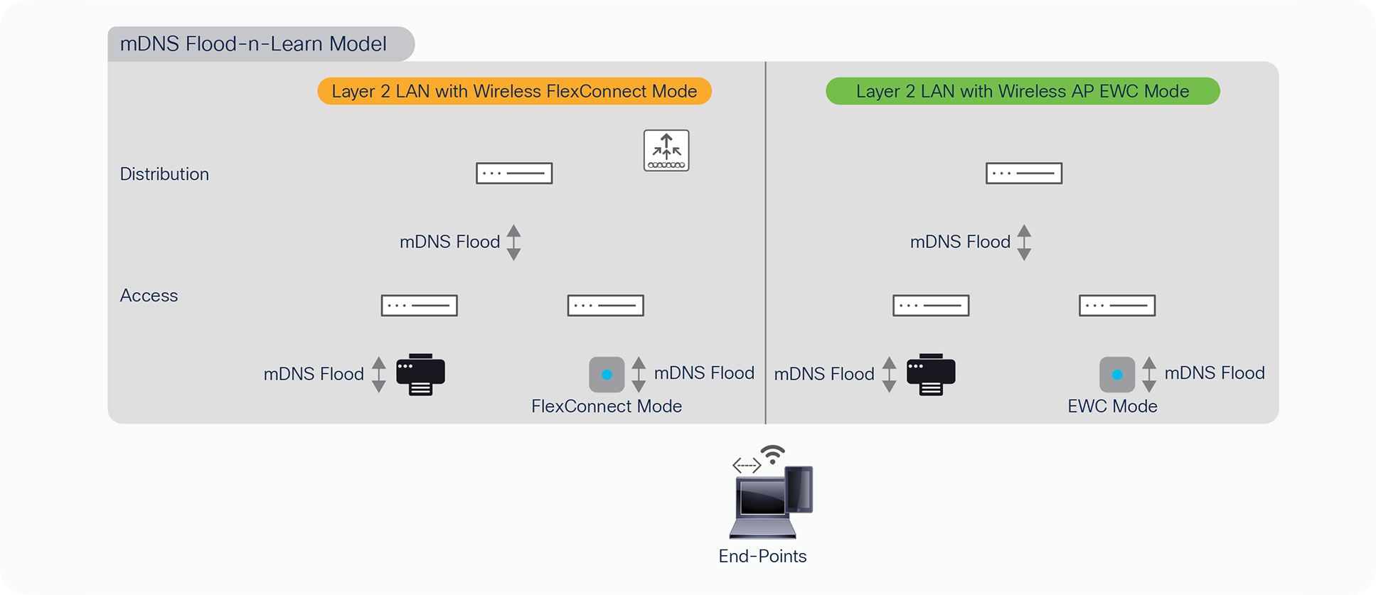
mDNS Flood-n-Learn based wired and wireless networks
Cisco DNA Service for Bonjour solution overview
The Cisco Digital Network Architecture (DNA) Service for Bonjour solution enables end-to-end Bonjour service-routing securely between Enterprise-grade advanced Wired and Wireless networks. The Cisco DNA Service for Bonjour solution also addresses problems relating to security, policy enforcement, and services administration on a large scale. The new distributed architecture is designed to eliminate mDNS flood boundaries and transition to unicast-based service routing, providing policy enforcement points and enabling the management of Bonjour services. With the Cisco DNA Service for Bonjour solution, the Enterprise networks can seamlessly introduce new services into the existing enterprise environment without modifying the existing network design or configuration.
The IT organization may optionally consider integrating Cisco DNA-Center to provide enhanced solution experience. The intuitive Cisco DNA-Center Wide Area Bonjour application GUI provides centralized access control and monitoring capabilities, combined with the scalability and performance required for large-scale Bonjour services deployments for various supporting enterprise network types. Figure – 2 below illustrates the Cisco DNA Service for Bonjour solution supporting unicast-based mDNS service-routing for Cisco Wireless FlexConnect, Embedded Wireless Controller (EWC) on Cisco Wireless 9100 series Access-Points (AP) or any distributed Wireless network solution.
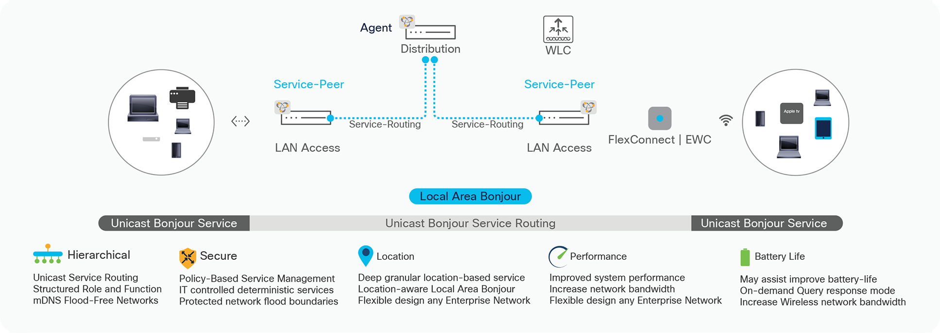
Cisco DNA Service for Bonjour Solution for Wireless FlexConnect and EWC
Cisco DNA Service for Bonjour solution benefits
The key benefits of Cisco DNA Service for Bonjour solution across Enterprise grade Wired and Wireless networks:
● End-to-End – The Cisco Wide Area Bonjour solution extends mDNS service discovery and distribution across Enterprise-grade Wired and Wireless networks without network boundaries. The Enterprise IT can build end-to-end, hierarchical, and structured service-oriented networks without introducing forklifting network re-design.
● Scale – The distributed mDNS service-routing solution across LAN and WLC systems decouples classic and centralized mDNS processing of WLC as single-gateway for entire network.
● Secure – The Enterprise IT gains control to introduce new services based on policy set on location, by role and more. The new Unicast-based model eliminates flood-n-learn based mDNS service model thus un-checked or out-of-policy services are implicitly denied using as consumer products introduces new capabilities.
● Experience – The end-user service discovery and distribution experience remain intact between residential and secure Enterprise networks. With zero learning-curve and agent-less mDNS service-routing solution, the IT can adapt new services as introduced in consumer products as they evolve without forklift network infrastructure redesign.
Solution Components
The Cisco DNA Service for Bonjour solution is an end-to-end solution that includes the following key components and system roles to enable unicast-based service routing across the Local Area and Wide Area Bonjour domain. Table – 1 below provides complete Cisco DNA Service for Bonjour solution matrix, service-routing support over commonly deployed Enterprise networks, operation and more.
Table 1. Cisco DNA Service for Bonjour Solution Support Matrix
|
|
Cisco DNA-Center Appliance |
Wide Area Bonjour App |
Catalyst 9600 |
Catalyst 9500 |
Catalyst 9400 |
Catalyst 9300 |
Catalyst 9200 |
Catalyst 9800 WLC |
| Platform Series |
DN2-HW-APL DN2-HW-APL-L DN2-HW-APL-XL |
|
Any |
Any |
Any |
Any |
Catalyst 9200 |
Any |
| Minimum Software |
2.2.2.0 |
2.2.2.0 |
17.6.2 |
17.6.2 |
17.6.2 |
17.6.2 |
17.6.2 |
17.6.2 |
| Supported Mode |
Platform |
Controller |
SDG-Agent Service-Peer |
SDG-Agent Service-Peer |
SDG-Agent Service-Peer |
SDG-Agent Service-Peer |
SDG |
Service Peer |
| Wide-Area Support |
- |
|
|
|
|
|
Not Supported |
- |
| Local-Area Support |
- |
|
|
|
|
|
|
|
| Service Scale |
- |
150000 |
15000 |
12000 |
10000 |
7500 |
1000 |
14000 |
| Software License |
||||||||
| Local and Wide-Are License |
- |
- |
Cisco DNA-Advantage |
Cisco DNA-Advantage |
Cisco DNA-Advantage |
Cisco DNA-Advantage |
Cisco DNA-Advantage |
Cisco DNA-Advantage |
| System Mode |
||||||||
| Cluster |
HA Cluster |
Multi-Instance |
StackWise Virtual |
StackWise Virtual |
StackWise Virtual |
StackWise-480 |
Cisco DNA-Advantage |
HA Cluster |
| Default |
Single Host |
Single Instance |
Standalone |
Standalone |
Standalone |
Standalone |
Standalone |
Standalone |
| Wired/Wireless Network Support |
||||||||
| Wired-Multilayer |
- |
|
|
|
|
|
|
- |
| Wired-Routed Access |
- |
|
|
|
|
|
|
- |
| Wireless-Local Mode |
- |
|
|
|
|
|
|
|
| Wireless-FlexConnect mode |
- |
|
|
|
|
|
|
Switch Gateway |
| Wireless-Catalyst 9100 EWC Mode |
- |
|
|
|
|
|
|
Switch Gateway |
| Overlay Network Support |
||||||||
| Cisco SD-Access |
- |
|
|
|
|
|
|
- |
| Cisco SD-Access Wireless |
- |
|
|
|
|
|
|
Switch Gateway |
| BGP EVPN VXLAN |
- |
|
|
|
|
|
- |
- |
| MPLS VPN |
- |
|
|
|
|
|
- |
- |
| Multi-VRF |
- |
|
|
|
|
|
|
- |
| Operation |
||||||||
| Assurance |
- |
|
- |
- |
- |
- |
- |
- |
| SNMP MIB Support |
- |
- |
|
|
|
|
|
- |
Endpoint Compatibility
As described earlier, the Cisco DNA Service for Bonjour solution follows industry standard RFC 6762 to communicate with Multicast DNS capable endpoints. Thus, the solution is compatible with any vendors following the standards including Apple, Google, Microsoft, Printer manufacturers and many more.
Target Audience
This document is targeted for Enterprise Wired and Wireless network administrators providing guidance on designing and deploying end-to-end Bonjour services. The content of this document primarily focuses on how to enable Bonjour services seamlessly into various types of Enterprise networks designs and topologies. This deployment guide provides guidance to evaluate existing network designs and system inventory along with simple step-by-step configurations guidelines for successful deployments.
This document does not cover basics of Bonjour implementation and it is highly recommended to refer to Apple Bonjour Overview document and RFC 6762 to learn Bonjour terminologies and operation.
Cisco DNA Service for Bonjour Architecture
The Cisco DNA Service for Bonjour solution supports three-tier distributed service-routing solution across broad-range of complex Enterprise network designs. The network administrator can refer to Cisco DNA Service for Bonjour Deployment Guide for Traditional LAN and Wireless Local Mode design and deployment. The small to mid-size Enterprise Layer 2 LAN network and distributed Wireless FlexConnect Local Switching or EWC 9100 series AP mode would need subset of solution to enable secure, scalable, and reliable service-oriented networks.
The Cisco DNA Service for Bonjour supports for such Wired and Wireless deployment size supports following two-tier hierarchical Bonjour solution that network administrator must understand and consider based on technical requirements:
● Local Area Bonjour Domain – The Local Area Bonjour enables unicast-based mDNS service routing across multiple Layer 2 Ethernet Switch or Wireless Access-Point in FlexConnect or EWC mode attached to same IP gateway in distribution network. The LAN Access switches configured in mDNS Service-Peer mode replaces flood-n-learn to unicast-mode with attached Wired and Wireless endpoints.
● Wide Area Bonjour Domain – The Wired and FlexConnect or EWC Wireless deployment is presumed to be limited to single IP gateway at Distribution layer, hence the Cisco DNA-Center is optional to monitor mDNS service assurance. The Cisco DNA-Center with Wide Area Bonjour is required when service-routing between two or more IP gateway for Wired and Wireless mDNS endpoints.
This sub-section describes network device modes, functions, and supporting traditional LAN and Wireless network designs in Enterprise. The distributed service-routing architecture of Cisco DNA Service for Bonjour assists in building unicast-based scalable, reliable, and resilient solution. Figure – 3 below illustrates multi-tier service architecture overview:
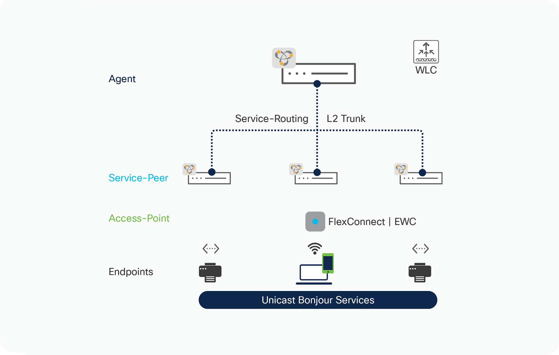
Cisco DNA Service for Bonjour Architecture
● SDG Agent: The Cisco Catalyst 9000 series switch at Layer 2/3 distribution functions in SDG agent mode, it builds unicast-based service-routing with downstream Layer 2 Cisco Catalyst 9000 switch to dynamically discover and route mDNS service information to another Layer 2 switch if required.
● Service Peer: At first hop the Layer 2 Cisco Catalyst 9000 series switch shall be configured in Service-Peer mode. It enables policy-based unicast communication with local attached Wired and FlexConnect or EWC mode Wireless endpoints in same or different VLANs and export service information to the upstream Cisco SDG agent in the distribution layer.
● Access-Point: Cisco Wireless Access-Point operating in FlexConnect Local-Switching or EWC mode. Any other Wireless solution terminating Wireless user VLAN on attached Layer 2 Catalyst 9000 series Ethernet switch in Service-Peer mode.
● Endpoints: A mDNS endpoint is any device that advertises or queries mDNS services conforming to RFC 6762. The mDNS endpoints can be in either LANs or WLANs. The Cisco Wide Area Bonjour solution is designed to integrate with RFC 6762 compliant Bonjour services, including AirPlay, Google Chrome cast, AirPrint, Dante Audinate and more.
Cisco FlexConnect Wireless Design
The Cisco FlexConnect wireless network can be deployed in central-switching or local-switching modes. The fundamental design principle to align the IP gateway and mDNS gateway on Cisco Catalyst switch remains consistent regardless of the wireless deployment modes. The core benefits of designing and implementing mDNS gateway on Cisco Catalyst 9000 series Ethernet switches is that it enables unicast-based services rich wired and wireless networks within Local Area Bonjour domain.
The IT organizations no need to merge Wired and Wireless VLANs or extend Wired VLANs to Cisco Wireless Access-Points for endpoints to discover mDNS services using flood-and-learn model. The Layer 2 trunk port connecting to Cisco Wireless FlexConnect or EWC AP mode shall only require carrying Wireless users VLAN providing better security, AP scalability and may improve Wireless network performance.
The Cisco Wireless LAN Controller supporting FlexConnect mode Access-Points can be deployed in following supported two modes:
● Appliance-based Controller – A physical appliance system deployed in central-site supporting control-plane processing to network-wide distributed Cisco Access Points in FlexConnect Local-Switching mode. The WLC physical appliance could be next-generation Cisco Catalyst 9800 series WLC or classic Cisco AireOS series WLC.
● Cloud-based Controller – A virtual Catalyst 9800 series WLC controller system hosted on private or public cloud network supporting centralized control-plane processing to network-wide distributed Cisco Access Points in FlexConnect mode. The virtual controller system could be next-generation Cisco Catalyst 9800-C series WLC deployed in different network scale packages. Figure 4 – below illustrates reference Cisco FlexConnect Wireless network design supporting unified Bonjour gateway solution across wired and wireless enabled networks:
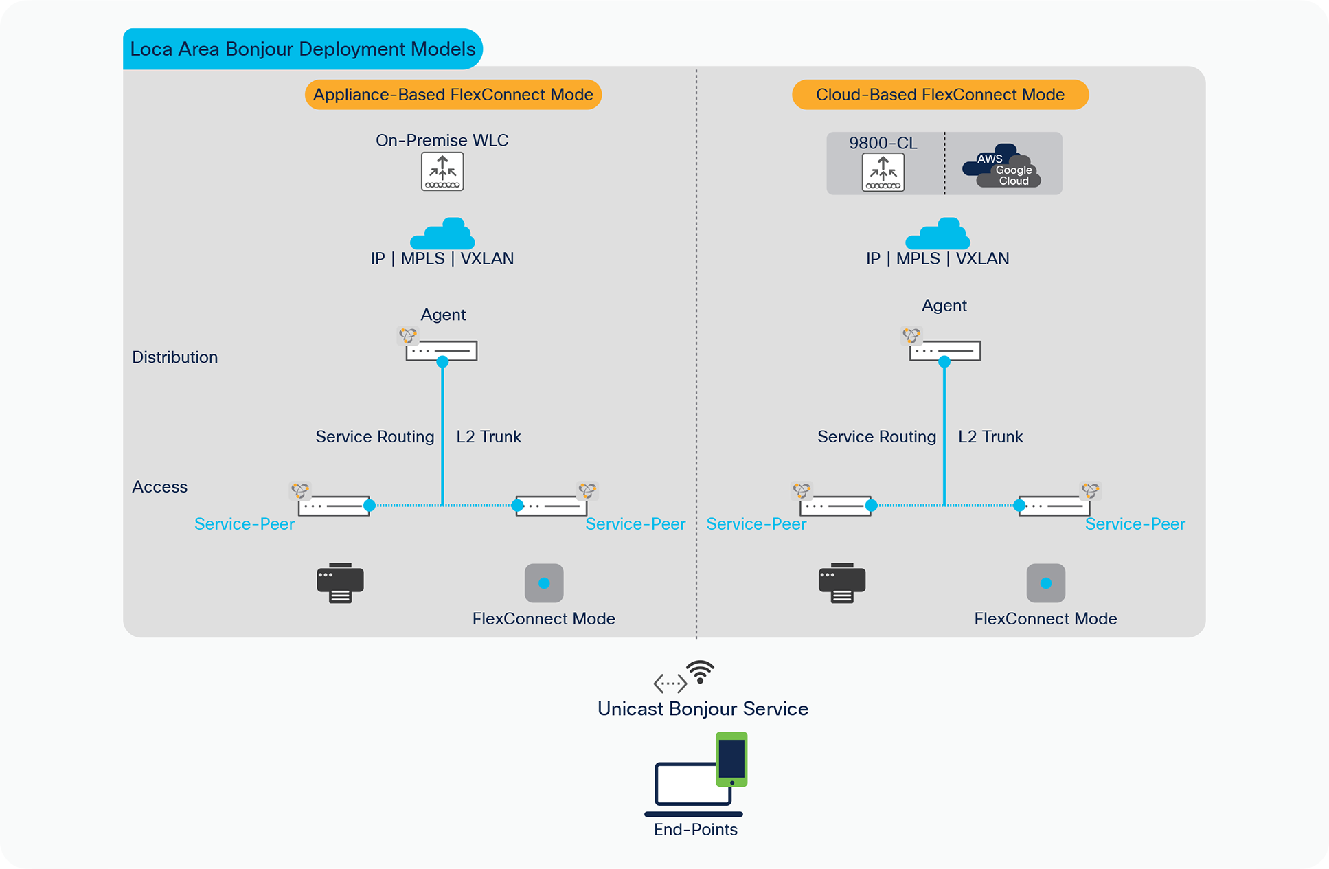
Cisco FlexConnect wireless network design
Local Area Bonjour service-routing
The Local Area Bonjour consists multiple Layer 2 Ethernet switches and FlexConnect or EWC mode Access-Points network devices providing unicast-based mDNS service-routing across same or different VLANs following IT defined policies. The Distribution layer Ethernet switch provides IP and service-routing gateway function between all Wired and Wireless mDNS end points across Layer 2 network instead flooding the network. The Cisco DNA-Center requirement is optional and can be deployed to enable mDNS service assurance.
The Cisco DNA Service for Bonjour solution supports various LAN and Wireless network designs commonly deployed in the Enterprise. Depending on network design the mDNS gateway mode requirement Layer 2 Ethernet switch, WLC and Access-Points series may vary. This sub-section provides brief benefits of Local Area Bonjour service-routing across commonly deployed LAN and Wireless network models. Figure – 5 below illustrates Enterprise-grade LAN and FlexConnect and EWC mode Wireless network designs supporting unicast-based service-routing to directly mDNS endpoints:
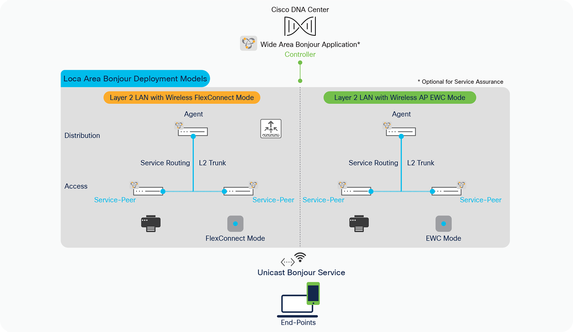
Local Area Bonjour design alternatives
The unicast-based mDNS service-routing solution at Layer 2 network can be seamlessly added in the network without disrupting existing Layer 2 VLAN, trunk configurations, Wireless mode settings etc. Upon successfully implementing the solution, the network administrator may optionally prune the Wired VLAN from AP trunk port if configured to enabled flood-n-learn based mDNS. Table – 2 below describes side-by-side comparison between unicast-based Local Area Bonjour and classic flood-n-learn based mDNS solution:
Table 2. Unicast vs Flood-n-Learn mDNS Comparison
|
|
Unicast mDNS Service-Routing |
Flood-n-Learn mDNS |
| Service Management |
Unicast Service-Routing |
Flood-n-Learn Based |
| L2 Switch Role |
Service-Peer |
Pass-Thru |
| L2 WLC Role |
N/A |
N/A |
| Access-Distribution Connection |
mDNS Trusted Trunk |
Standard L2 Trunk |
| L2 Switch Flood Application |
Broadcast Unknown Unicast Link-Local Multicast (non-mDNS) |
Broadcast Unknown Unicast Link-Local Multicast |
| Layer 2 mDNS |
Route – IPv4 and IPv6 |
Flood – IPv4 and IPv6 |
| Service Boundary |
Policy-Based – Wired and Wireless Individual – Switch | VLAN | Port-Group | Port |
Entire Layer 2 Broadcast Domain |
| Service Policy Security |
IT defined on Service-Peer |
Unsupported |
| Location-Based Service |
Policy-Based – Wired and Wireless Individual – Switch | VLAN | Port-Group | Port |
Unsupported |
Policy management
The network remains unsecure and vulnerable to manage mDNS security with classic flood-n-learn based networks. The network administrators have limited controls and visibility to identify, secure and manage mDNS services in Layer-2 network environments. As Cisco Catalyst LAN switching and Wireless portfolio introduces unicast-based mDNS service management it enables new possibilities for IT organizations to build secure and end-to-end service-routing enterprise networks.
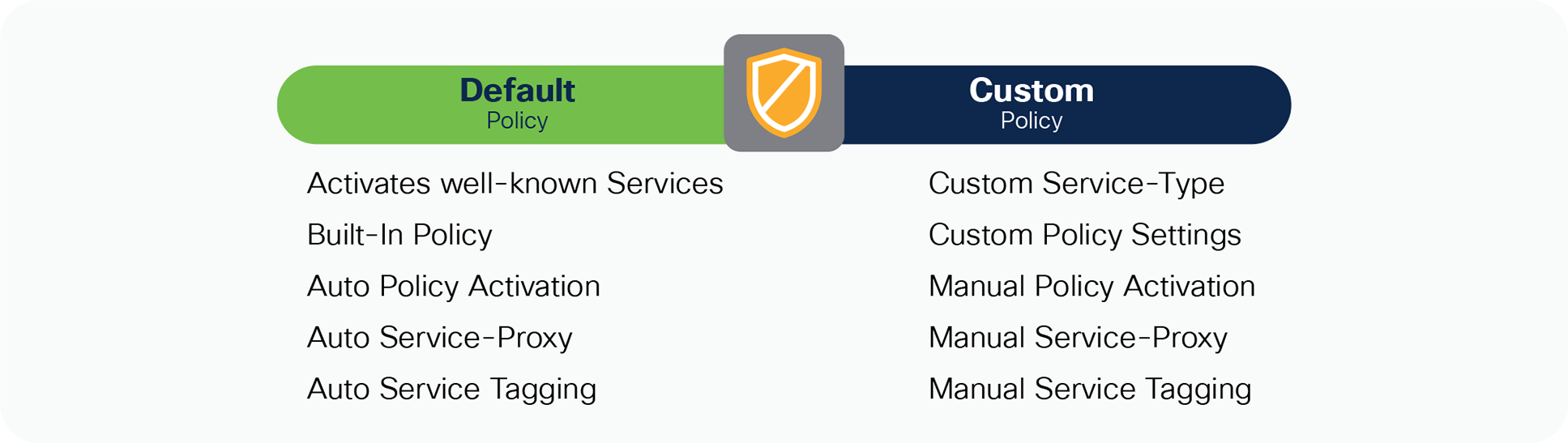
The Cisco IOS-XE 17.6.2 software version introduces new flexible policy configuration model providing network administrator to design and build simplified or custom tailored mDNS service-routing Wired and Wireless networks. Figure 6 – below illustrates the new Cisco IOS-XE built-in and default policy model to activate unicast-based mDNS service-routing on intended Wired VLAN or Wireless Profile. The Cisco Catalyst switch and WLC continue to support custom policy when upgrading from previous software version or need tailored policies solution.
Flexible Cisco IOS-XE service-routing policy model
The Cisco IOS-XE provides support co-existence of Default and Custom policy on same system. Based on requirement the administrator can implement policy in either or both mode on per Wired VLAN and Wireless Profile basis:
Table 3. Flexible Cisco IOS-XE service-routing policy comparison
|
|
Default Policy |
Custom Policy |
| Local Area Bonjour – Service-List Permit |
Built-In. Default bi-directional services permitted * |
Custom. User-defined uni-directional custom service permission |
| Local Area Bonjour – Service-Policy |
Built-In. Automatically binds default Service-List |
Custom. User-defined custom service-list binding |
| Local Area Bonjour – Service-Policy |
Built-In. Automatically associates default policy to mDNS gateway enabled Wired VLAN and Wireless Profile |
Custom. User-defined manual policy association to mDNS gateway enabled Wired VLAN and Wireless Profile |
|
|
Default Policy |
Custom Policy |
| Local Area Bonjour – Wired Inter-VLAN Service-Proxy |
Built-In. Automatic Inter-VLAN Service-Proxy on L2 Switch |
Custom. User-Defined manual inter-VLAN location-filter on L2 Switch |
| Location-Tag – Wired Port and FlexConnect/EWC Mode AP |
Built-In. Default Tag (0) to Wired Port and FlexConnect/EWC Mode AP |
Built-In or Custom. Default Tag (0) or custom tag assigned to Wired Port and FlexConnect/EWC Mode AP |
Location-group based service-routing
The classic mDNS flood-n-learn based Cisco Wireless FlexConnect or EWC network deployments unable to provide location-based mDNS solution for Wired and Wireless mDNS endpoints. The key challenge on LAN side is to dynamically identify, tag and extend granular location details for Wired mDNS services connection. In a Layer 2 mDNS flood environment it has not been possible to detect exact mDNS endpoint connection across Wired Layer 2 networks and distributing with granular details to FlexConnect or EWC mode Wireless endpoints.
Cisco DNA Service for Bonjour solution enables zero-configuration vision with introduction of mDNS service-routing based on Location-Tag mapped to Wired LAN Ports and Cisco Wireless Access-Points. The Cisco Catalyst 9000 series LAN switches expands policy tuple with inclusion to assign Location- Group tag for service discovery and distribute mDNS services matching administrator defined tags. The mDNS service Location-Tag on Wired LAN Ports and Wireless Access Points are dynamically synchronized across complex Enterprise network environments and without introducing forklift changes impacting mission-critical network environments.
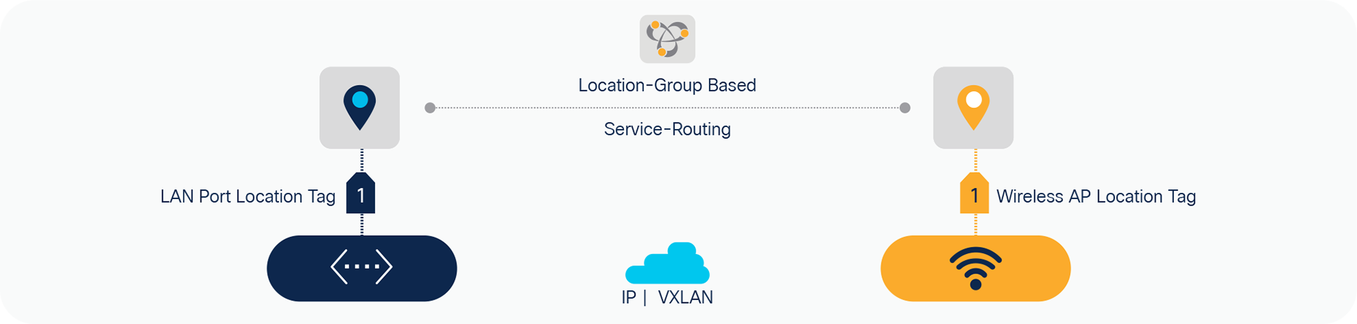
Location-tag based service-routing
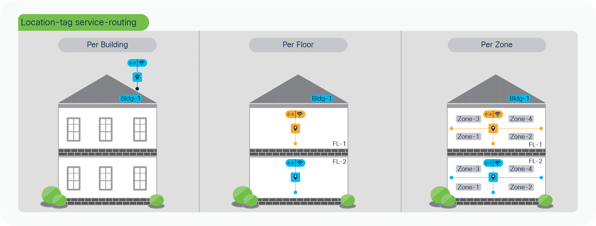
As end-to-end mDNS processing transforms to unicast-based service and provides flexibility to tag mDNS services for granular service-routing, the Cisco DNA Service for Bonjour enables new possibilities for IT organization to design and implement end-to-end, secure, and scalable service-oriented solution. To provide the best-in-class user-experience the IT administrator can design and build Location-tag based dynamic mDNS service boundaries at individual building, floor, or micro-segmented service-zones on each floor. As mDNS service discovery boundary shrinks the user-experience improves in easily navigating limited IT managed or Peer-to-Peer service provider list within tailored close-proximity.
The IT organization can design and build mDNS policies enabling secure service experience to the end-users, i.e., In Bldg-1, James can discover and use Wired Apple-TV and Printer from his iPhone. In Bldg-2, James should only see Apple-TV and he shall not be able to find any mDNS services when connected to Bldg-3 wireless network. Figure – 8 below illustrates some common Location-Tag based user-cases that IT can enable across Enterprise Wired and Wireless networks:
Location-tag based mDNS use-cases
Deploying local area Bonjour Domain
This section provides guidelines to implement unicast-based mDNS service-routing in Local Area Bonjour domain that is common deployment model supporting collapsed Wired and Wireless networks to common IP gateway switch in Distribution layer. As described earlier, the Local Area Bonjour consists of multiple Layer 2 Ethernet switches, Wireless controllers and Access-Points connecting to some common IP gateway for their Wired and Wireless endpoints. For such deployment models, the Cisco DNA-Center is optional capabilities that can provide central service assurance capabilities. Figure – 9 below illustrates reference unicast-based Local Area Bonjour domain enabling service-routing capabilities between Layer 2 Ethernet switches supporting FlexConnect Local Switching or EWC 9100 AP Wireless modes:
Unicast-based local area Bonjour Design
Local Area Bonjour Pre-requisite configuration
Prior configurating mDNS service-routing capabilities it is imperative basic pre-requisite configurations are applied on targeted network devices to successfully implement unicast-based mDNS service-routing:
● Software and License – The minimum software version Cisco IOS-XE 17.6.2 and network devices with DNA-Advantage license is required to implement capabilities described in this guide.
● IP Reachability – Ensure the LAN Access in Service-Peer mode have basic IP connectivity in same VLAN and subnet with Distribution-layer SDG Agent switch. The LAN management VLAN can be leveraged to enable service-routing.
● WLC mDNS Gateway – Ensure mDNS gateway on Cisco Catalyst 9800 WLC supporting FlexConnect Local-Switching is disabled. Similarly, the Catalyst 9100 series in EWC mode must also disable mDNS gateway function. The Cisco Catalyst LAN switch provides unified mDNS gateway for Wired and Wireless endpoints.
This section provides the reference configuration guidelines using default and custom mode for collapsed Wired and Wireless networks. Table – 4 below provides the default policy mode side-by-side reference configuration enabling mDNS service-routing between Layer 2 Ethernet switch in Service- Peer mode and the IP gateway enabled as SDG Agent. In this mode, several well-known white-listed mDNS service-types are by default permitted in Local Area Bonjour domain.
Default policy mode configuration
Table 4. Local Area Bonjour Service-Routing with default mode policy configuration
| LAN-Access |
Distribution |
WLC |
| Mode: Service-Peer |
Mode: Agent |
N/A |
| Step – 1: Default Policy Mode – mDNS Service-Routing |
||
| ! mdns-sd gateway mode service-peer active-query timer 1 sdg-agent 10.1.1.254 ! vlan configuration 11,12, 101 ! Printer, Wired and Wireless User VLAN mdns-sd gateway ! |
! mdns-sd gateway mode sdg-agent ! vlan configuration 11,12, 101 ! Printer, Wired User VLAN, Wireless User VLAN Range mdns-sd gateway |
No mDNS configuration required for FlexConnect or EWC Mode AP. |
| Step – 2: Default Policy Mode – mDNS Trusted Service-Routing Interface |
||
| ! interface Po1 description TO DIST mdns-sd trust ! |
! interface Po1 description TO LAN ACCESS mdns-sd trust ! |
|
Custom policy mode configuration
The advanced mode mDNS service-routing can be deployed with user-defined custom policy for Wired and Wireless networks. The Cisco IOS-XE built-in default mode mDNS policy is replaced with custom policy once applied under targeted Wired and Wireless endpoint VLAN of Layer 2 Service-Peer mode switch. The default and custom policy mode can co-exist on same mDNS gateway system, hence based on requirements the Cisco IOS-XE provides flexible solution to use default and custom policy on same Catalyst Ethernet switch. Table – 5 below provides the custom policy mode reference configuration enabling mDNS service-routing on Layer 2 LAN and Wireless Access Ethernet switch and Distribution Layer switch.
Table 5. Local Area Bonjour Service-Routing with custom mode policy – LAN Access switch configuration
| LAN-Access |
Distribution |
WLC |
| Mode: Service-Peer |
Mode: SDG-Agent |
N/A |
| Step – 1: Custom Policy Mode – LAN Distribution SDG-Agent Service-Routing |
||
| ! mdns-sd gateway mode service-peer active-query timer 1 sdg-agent 10.1.1.254 ! interface Po1 description TO DIST mdns-sd trust ! |
! mdns-sd gateway mode sdg-agent ! vlan configuration 11,12, 101 ! Printer, Wired User VLAN, Wireless User VLAN Range mdns-sd gateway ! interface Po1 description TO LAN ACCESS mdns-sd trust ! |
No mDNS configuration required for FlexConnect or EWC Mode AP. |
| Step – 2: Custom Policy Mode – mDNS Service-Policy |
||
| ! mdns-sd service-list LOCAL-AREA-BONJOUR-IN IN match apple-airprint ! mdns-sd service-list LOCAL-AREA-BONJOUR-OUT OUT match apple-airprint ! mdns-sd service-policy LOCAL-AREA-BONJOUR-POLICY service-list LOCAL-AREA-BONJOUR-IN IN service-list LOCAL-AREA-BONJOUR-OUT OUT ! |
|
|
| Step – 3: Custom Policy Mode – LAN Access Inter-VLAN Service Local Proxy |
||
| ! mdns-sd location-filter LOCAL-PROXY match location-group default vlan 11 ! mdns-sd service-list LOCAL-AREA-BONJOUR-OUT OUT match apple-airprint location-filter LOCAL-PROXY |
! mdns-sd gateway mode sdg-agent ! vlan configuration 11,12, 101 ! Printer, Wired User VLAN, Wireless User VLAN Range mdns-sd gateway ! interface Po1 description TO LAN ACCESS mdns-sd trust ! |
No mDNS configuration required for FlexConnect or EWC Mode AP. |
| Step – 4: Custom Policy Mode – mDNS Service-Policy Association |
||
| ! Wired Printer (11), Wired User VLAN (12) and Wireless User VLAN (101) ! vlan configuration 11,12, 101 ! mdns-sd gateway service-policy LOCAL-AREA-BONJOUR-POLICY |
|
|
Deploying location-group based service-routing
Default policy mode location-group service-routing
The Enterprise organization office size broadly varies by buildings, floors, and outdoor areas. The Location-Group based service-routing may require building tailored service-routing to limit the mDNS service discovery within building to support enhanced user-experience. This sub-section augments Location-Group based service-routing based on above-described default mode configuration in Table – 6.
This section is divided in three most commonly location-based service-routing. Each sub-section provides reference configuration to build policy from broad to deep granular mDNS to support intuitive zero-configuration user-experience, network, service security, and more. Based on IT organization requirements, the default or user-defined Location-Group tag and mDNS policies can be adjusted to implement the solution at per-building, per-floor, and per-zone on each floor level.
With default Location-Group tag, the mDNS service discovery boundary to Wired and Wireless endpoints is limited to single Layer 2 Ethernet switch. The network administrator may expand service discovery boundary as described in this section.
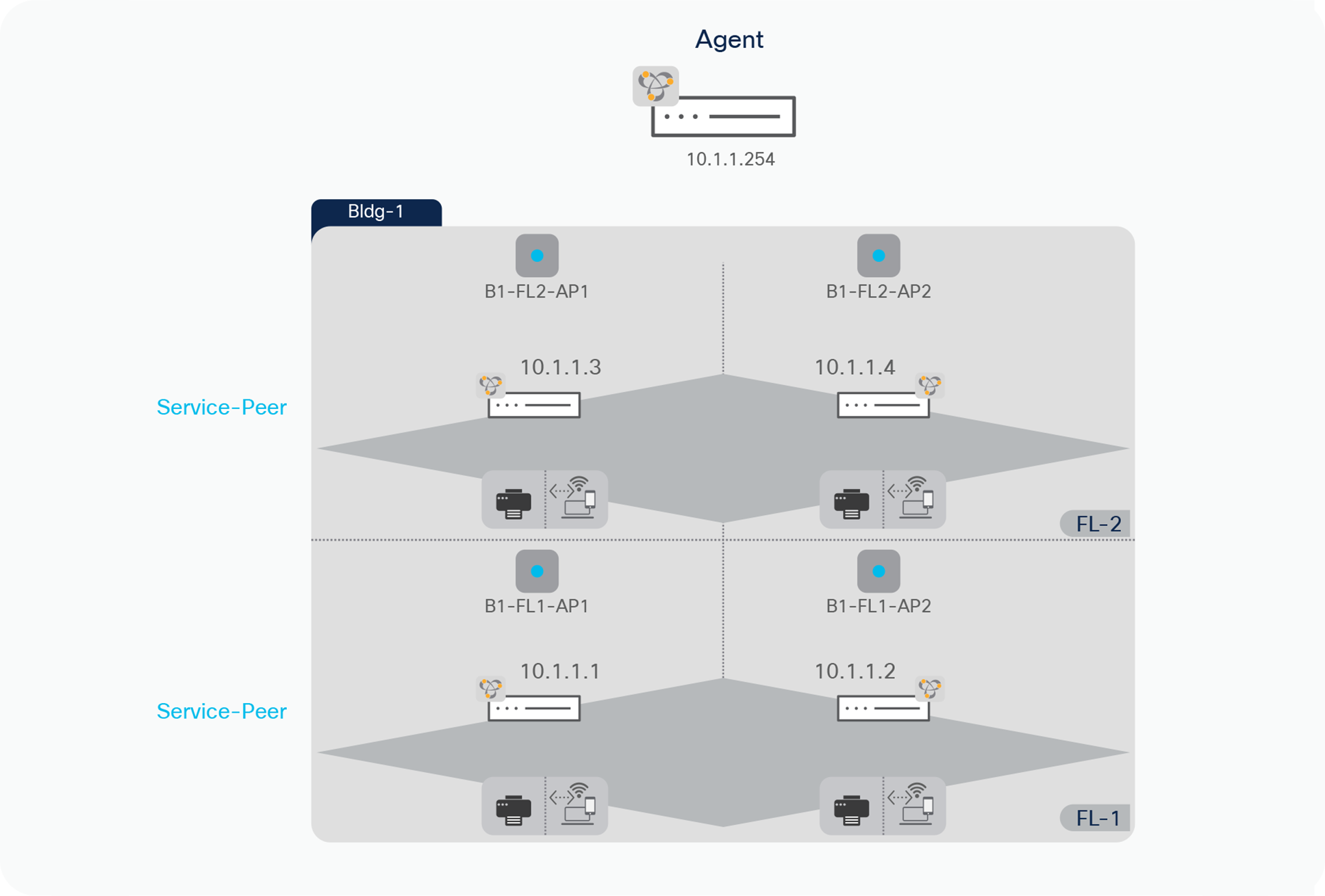
Per-building location-group configuration
The network administrator can group one or more LAN Ethernet switches and logically tag Wireless Access-Points deployed on targeted building across one or more floors. In Local Area Bonjour domain, the Cisco Catalyst 9000 series switches in LAN distribution-layer can group multiple Service-Peers such as Layer 2 LAN Access switches to support Location-Tag based service-routing on per-building basis.
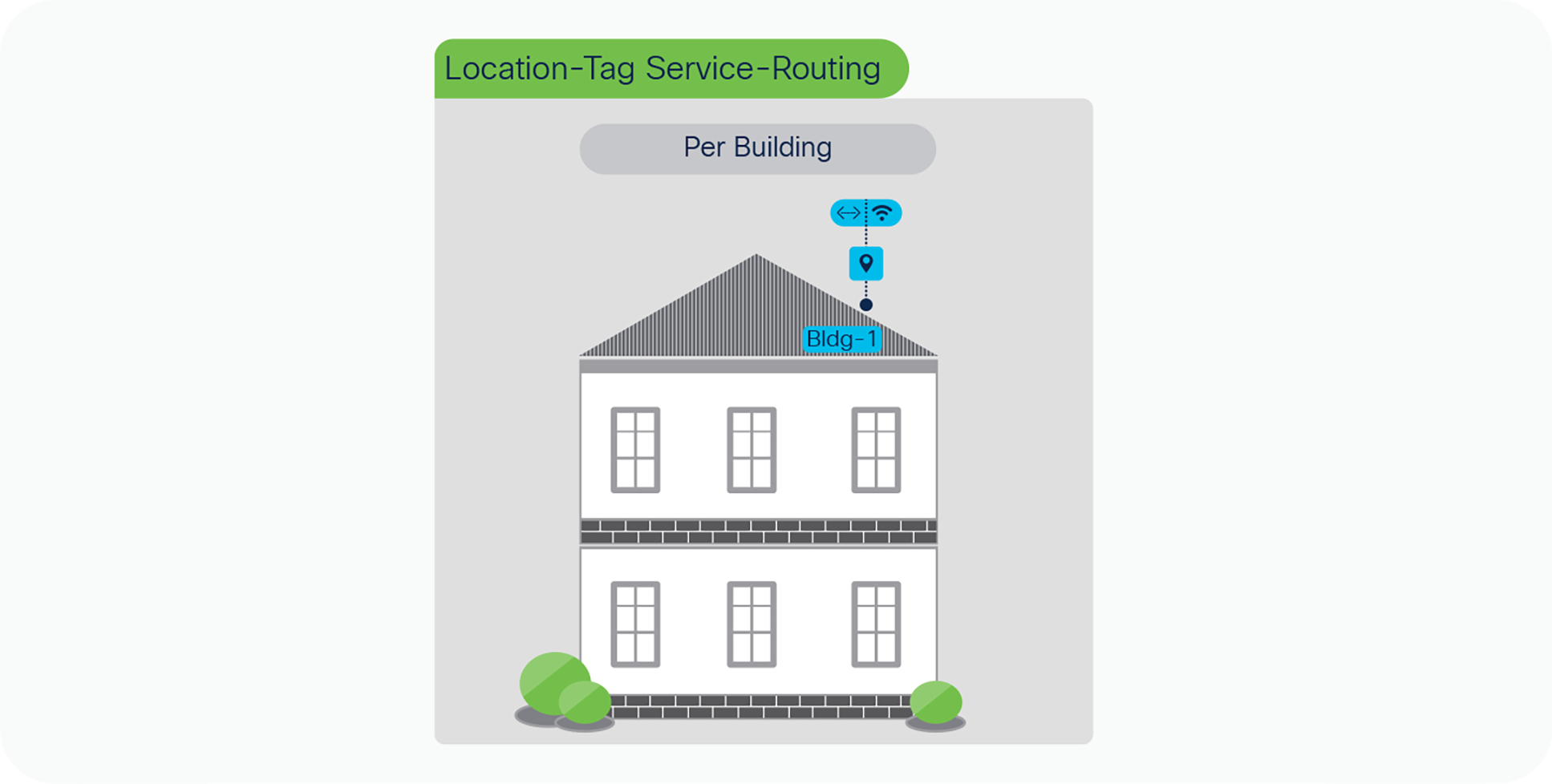
Per-building location-group service-routing
Table 6. Per-building location-group service-routing plan
|
|
Building – 1 |
| Floor – 1 Service-Peer Group |
L2 LAN Switch IP: 10.1.1.1 – 10.1.1.2 |
| Floor – 2 Service-Peer Group |
L2 LAN Switch IP: 10.1.1.3 – 10.1.1.4 |
Table – 7 below describes step-by-step procedure to build service-routing and enable Per-Building Location-Group based mDNS by combining all Service-Peer switches in single Peer-Group of Local Area Bonjour domain.
Table 7. Local Area Bonjour – Per-building location-group service-routing configuration
| LAN Access |
LAN Distribution |
| Service-Peer |
Agent |
| Step – 1: Default Policy Mode – mDNS Service-Routing |
|
| ! This is pre-requisite step. Refer to Wide Area Bonjour configuration procedure described above in Table – 4. ! |
|
| Step – 2: Per-Building – Enable Location-Group based Service-Routing |
|
| ! Default Location-Group (0) on LAN switchport. No configuration required. |
! mdns-sd service-peer group ! Create Bldg-1 Service Peer-Group for all Layer 2 LAN Access Switch peer-group 1 service-policy default-mdns-service-policy service-peer 10.1.1.1 location-group default … service-peer 10.1.1.4 location-group default ! |
Per-Floor Location-Group Configuration
The mDNS service-routing boundary for Wired and Wireless endpoints can be reduce to per-floor level. The user-experience becomes more intuitive to dynamically discover mDNS services based on their physical presence on individual floor instead entire building. To support zero-configuration and secured user-experience the service provider listings are dynamically updated on user mobile devices as they roam between buildings and floors.
The principle of per-floor mDNS policy are same as building-level, however the key difference is how service-peer grouping is performed at distribution layer switch. The network administrator can configure multiple peer-groups on LAN distribution grouping LAN Access switches on per-floor basis instead entire building. The Wired and FlexConnect or EWC AP mode Wireless users can discover and distribute mDNS services limited on per-floor basis.
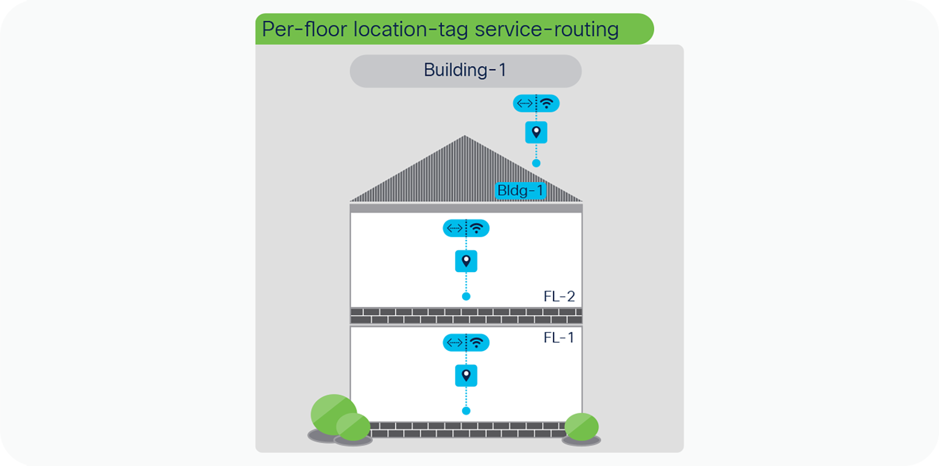
Per-floor location-group service-routing
Table 8. Local Area Bonjour – Per-floor location-group service-routing configuration
| LAN Access |
LAN Distribution |
| Mode: Service-Peer |
Mode: Agent |
| Step – 1: Default Policy Mode – mDNS Service-Routing |
|
| ! This is pre-requisite step. Refer to configuration procedure described above in Table – 4. ! |
|
| Step – 2: Per-Floor – Enable Location-Group based Service-Routing |
|
| ! Default Location-Group (0) on LAN switchport. No configuration required. |
! mdns-sd service-peer group ! Create Bldg-1 Service Peer-Group for per-Floor Layer 2 LAN Access Switch peer-group 1 service-policy default-mdns-service-policy service-peer 10.1.1.1 location-group default service-peer 10.1.1.2 location-group default peer-group 2 service-policy default-mdns-service-policy service-peer 10.1.1.3 location-group default service-peer 10.1.1.4 location-group default ! |
Per-zone location-group configuration
The per-floor based mDNS service-routing boundary can be further sub-divided into logical services zones to enable deep granular and close-proximity based user-experience. The IT administrator can create logical services zones based on building floorplans, each individual service zones can match installed LAN switchports and Wireless Access-Points in the area. The mDNS Location-Group tags can be assigned to individual or group of Ethernet ports of LAN Access switches. The Ethernet ports can be connected Wired mDNS endpoints and FlexConnect or EWC mode AP.
The zone-based service-routing extends the key mobility and security benefits from building or floor level supporting close-proximity and secure service-routing solution to allow or dis-allow service service-routing based on their physical presence in specific IT defined service zones of a building floor.
The network administrator can group one or more Ethernet ports connected to Wired and AP Ports of LAN Access switches and assign logical tag. Each Layer 2 Access switches can support up to 4096 Location-Group and configuration task described below in Table – 12 can be repeated on other Layer 2 Access switches to build service-zones.
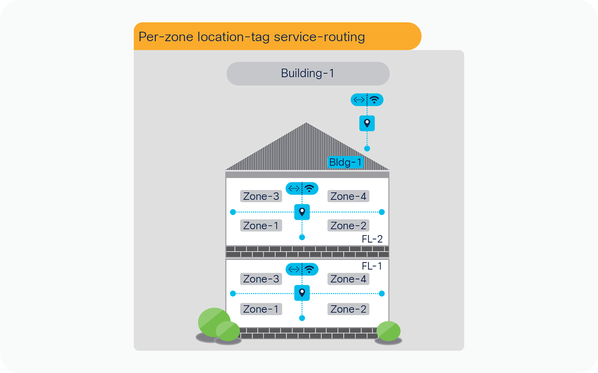
Per-zone location-group service-routing
Table 9. Wide Area Bonjour – Per-zone location-tag service-routing configuration
| LAN-Access |
LAN Distribution |
| Mode: Service-Peer |
Mode: Agent |
| Step – 1: Default Policy Mode – mDNS Service-Routing |
|
| ! This is pre-requisite step. Refer to configuration procedure described above in Table – 4. ! |
|
| Step – 2: Per-Zone – Enable Location-Group based Service-Routing |
|
| ! LAN Access – 10.1.1.1 – Zone-1 Location-Group ID 1 Configuration ! interface range Gi1/0/1 – 10 description Connected to AirPrint and FlexConnect/EWC AP’s ! mdns-sd location-group 1 vlan 10 interface Gi1/0/1 … interface Gi1/0/10 ! |
! Per Zone configuration is assumed to be on Single L2 Access switch connecting Wired users and Wireless AP. Hence no configuration on LAN Distribution is needed. |
| ! LAN Access – 10.1.1.1 – Zone-2 Location-Group ID 2 Configuration ! interface range Gi1/0/11 – 20 description Connected to AirPrint and FlexConnect/EWC AP’s ! mdns-sd location-group 2 vlan 10 interface Gi1/0/11 … interface Gi1/0/20 ! |
|
Scale and Performance Support Matrix
The Cisco DNA Service for Bonjour solution is fully distributed mDNS service-routing solution hence it provides high scale solution for large size Enterprise networks. Each product in overall solution scales differently due to different level of system resources.
Table 10. Cisco DNA-Center Wide Area Bonjour Scale and Performance Matrix
| Cisco DNA Center |
Service Scale |
Release |
| DN2-HW-APL DN2-HW-APL-L DN2-HW-APL-XL |
150,000 Services Scale 1000 SDG Agent |
Cisco DNA-Center – 2.2.3 Cisco Wide Area Bonjour Application |
Table 11. Cisco IOS-XE mDNS Scale and Performance Matrix
| Platform |
Mode |
Service Scale |
Release |
| Cisco Catalyst 9300 |
Service-Peer or Agent |
7500 |
17.6.2 |
| Cisco Catalyst 9400 |
Service-Peer or Agent |
10000 |
17.6.2 |
| Cisco Catalyst 9500 |
Service-Peer or Agent |
12000 |
17.6.2 |
| Cisco Catalyst 9500-H |
Service-Peer or Agent |
12000 |
17.6.2 |
| Cisco Catalyst 9600 |
Service-Peer or Agent |
15000 |
17.6.2 |
| Cisco Catalyst 9800-80 WLC |
Service-Peer |
14000 |
17.6.2 |
| Cisco Catalyst 9800-40 WLC |
Service-Peer |
12000 |
17.6.2 |
| Cisco Catalyst 9800-L WLC |
Service-Peer |
4000 |
17.6.2 |
| Cisco Catalyst 9800-CL WLC |
Service-Peer |
2000 |
17.6.2 |
Cisco DNA Service for Bonjour is enterprise-grade Wide Area Bonjour solution designed to seamlessly integrated into complex wired and wireless network infrastructure. The Cisco Wide Area Bonjour retains original end-users experience for using Bonjour technology in Enterprise. In addition, the new solution provides plug-n-play service-routing capabilities without any forklift changes in DHCP/DNS servers or manual MAC address management.
The new distributed architecture supports unparallel scale, performance, security, and redundancy that offers vendor agnostic compatible solution to enable end-to-end services rich network infrastructure between computers, IoT and more.
CCO Solution
Cisco DNA Service for Bonjour - Solution Landing Page
At-A-Glance
Cisco DNA Service for Bonjour Solution At-A-Glance
Cisco DNA Service for Bonjour Deployment Guide
Cisco DNA Service for Bonjour Deployment Guide – Traditional LAN and Wireless Local Mode
Cisco DNA Service for Bonjour Deployment Guide – Cisco Software-Defined Access Mode
Quick Configuration guides
Cisco DNA Service for Bonjour Quick Configuration Guide
Cisco DNA Service for Bonjour CCO Configuration Guide
Cisco Catalyst 9300 Series Switches
Cisco Catalyst 9400 Series Switches
Cisco Catalyst 9500 Series Switches
Cisco Catalyst 9600 Series Switches
Cisco Catalyst 9800 Series WLC
Cisco Catalyst 9100 Series – Embedded Wireless LAN Controller
Cisco DNA-Center – Wide Area Bonjour User Guide