Cisco Catalyst SD-WAN and Microsoft SSE Solution Integration User Guide
Available Languages
Bias-Free Language
The documentation set for this product strives to use bias-free language. For the purposes of this documentation set, bias-free is defined as language that does not imply discrimination based on age, disability, gender, racial identity, ethnic identity, sexual orientation, socioeconomic status, and intersectionality. Exceptions may be present in the documentation due to language that is hardcoded in the user interfaces of the product software, language used based on RFP documentation, or language that is used by a referenced third-party product. Learn more about how Cisco is using Inclusive Language.
Cisco and Microsoft's Secure Service Edge (SSE) solution have collaborated to enhance the security of customer branch internet traffic through efficient redirection. The integration of Cisco Catalyst® SD-WAN with Microsoft's SSE solution facilitates inspection of north-south traffic originating from SD-WAN branches destined for the internet or Software-as-a-Service (SaaS) applications routed through Microsoft's SSE solution.
This guide details the process of securing Cisco Catalyst SD-WAN sites using Microsoft's SSE solution specifically for internet and SaaS applications. The integration has undergone extensive testing and validation for deployment on Cisco IOS® XE SD-WAN routers running software versions 17.12 or 20.12, in conjunction with the Microsoft's SSE solution cloud dashboard. A key customer benefit is the seamless deployment of a comprehensive end-to-end SD-WAN and security solution.
Microsoft Entra Internet Access and Microsoft Entra Private Access are integral components of Microsoft's SSE solution. Microsoft Entra Internet Access ensures secure access to internet and SaaS apps, providing robust protection for users, devices, and data against internet-borne threats. This document focuses on the Internet Access use case.
Overview of configuration steps
Step 1. Create remote networks using the Microsoft Entra Admin Center.
Step 2. Establish connectivity—Configure an IPsec tunnel in Cisco Catalyst SD-WAN Manager using a SIG parcel.
Step 3. Redirect traffic—Configure data policy for application-based traffic redirected from branch edge devices.
Step 4. Validate the configuration.
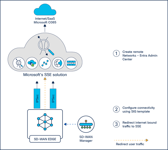
Integration between Catalyst SD-WAN and Microsoft's SSE solution
Step 1. Create remote networks using the Microsoft Entra Admin Center
Remote networks enable administrators to define and configure remote network locations, including names, regions, and bandwidth capacity, and add one or more Customer Premises Equipment (CPE) links to a given remote network.
Overview
● Create two different remote networks in two different regions. For each remote network, create two links. Each of these links will be used for active/backup tunnel configuration when designing High Availability (HA) pairs on CPE.
● For each link definition, fill in the basic link details, IPsec-related security attributes, and IKEv2 values.
Workflow
1. On the Microsoft Entra Admin Center homepage, select Global Secure Access (preview) > Connect > Remote Networks, and click the Create Remote Network button.
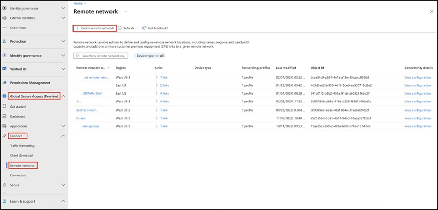
Creating a remote network in the Microsoft Entra Admin Center
2. On the Basics tab, fill in the remote network name and select the region.
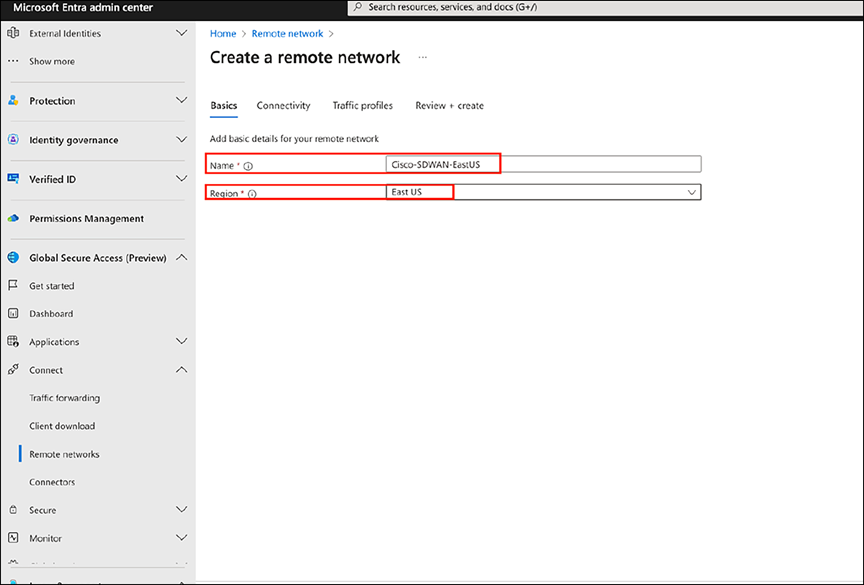
Entering the network name and region
3. On the Connectivity tab, create two links for the CPE to ensure the creation of multiple tunnels, with the same remote endpoint (CPE public IP) but different local endpoints. Users can set up two or more tunnels based on their requirements.
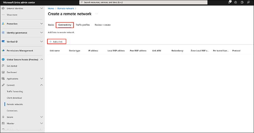
Adding connectivity links
Note: Cisco uses policy-based packet redirection to tunnel for Microsoft apps. Therefore, Cisco routers do not require Border Gateway Protocol (BGP) for prefixes from Microsoft's SSE solution. Users should enter dummy values for BGP-related fields, as they are marked mandatory on the UI but do not affect tunnel establishment and routing.
3a. For link1 (Cisco-SDWAN-EastUS-Link1), fill in the general information including link name, device type (select “other”), IP address (CPE public IP), local BGP address, peer BGP address, link ASN, redundancy, and bandwidth capacity (Mbps).
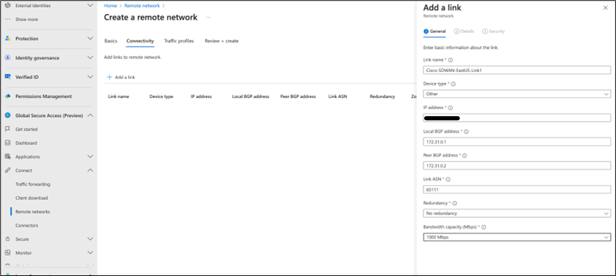
Providing general link information
3b. On the Details tab of the Add a Link pane, fill in the IPsec and IKE v2 information.
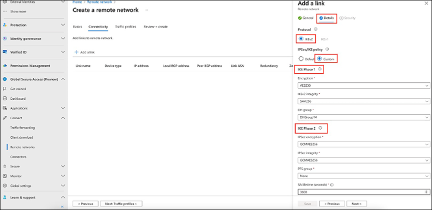
Specifying IPsec and IKEv2 information
3c. On the Security tab of the Add a Link pane, fill in the Pre-Shared Key (PSK) value.
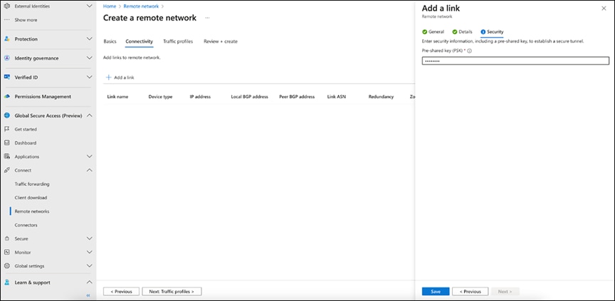
Providing the PSK value
4. Create another link (Cisco-SDWAN-EastUS-Link2) for the same remote network by filling in details similar to those for link1 (Cisco-SDWAN-EastUS-Link1).
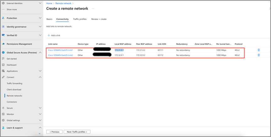
Creating a second link
5. On the Traffic Profiles tab of the remote network, select which traffic is to be allowed through these links. Currently, only the Microsoft 365 traffic forwarding profile is available for selection.
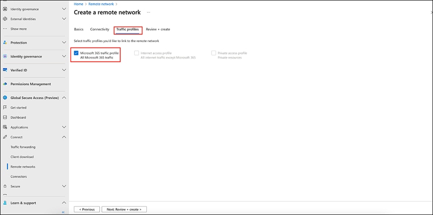
Completing the Traffic Profiles tab
6. Review and create the remote network as the final step.
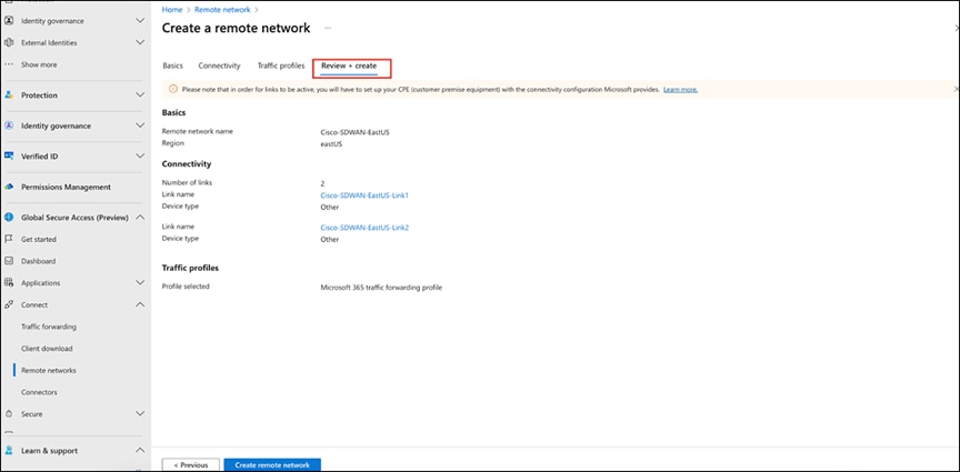
Reviewing and creating the remote network
7. Optional steps are needed when CPE uses multiple HA pairs. Create another remote network in the west region with two links, using values similar to those used for the remote network in the east region.
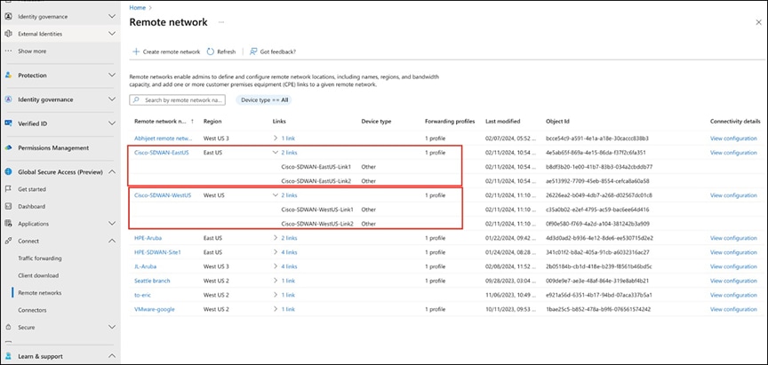
Creating another remote network in the west region
8. Users can click the View Configuration option for each remote network to see the data center IPs and IKE encryption/auth details to be used in Cisco Catalyst SD-WAN Manager.
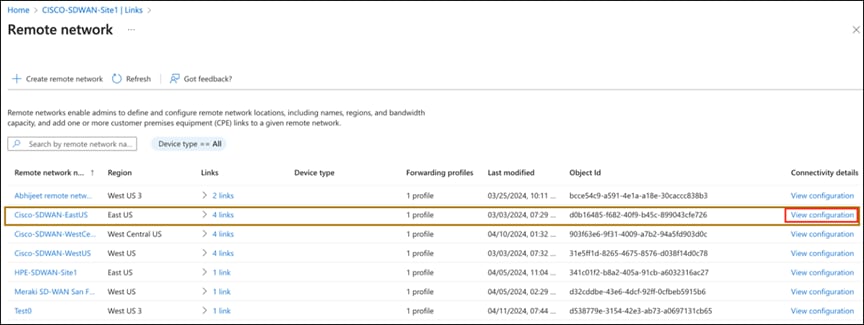
Locating the View Configuration option
Step 2. Configure an IPsec tunnel in Cisco Catalyst SD-WAN Manager using a SIG parcel
1. Configure the IPsec tunnel in Cisco Catalyst SD-WAN Manager using a Secure Internet Gateway (SIG) parcel. This configuration establishes a secure remote network connection between Microsoft's SSE solution and the Cisco Catalyst SD-WAN using an IPsec tunnel.
2. Set up tunnels using SIG templates: On the Catalyst SD-WAN Manager dashboard, select Configuration -> Policy Group -> Secure Internet Gateway (SIG).
3. Click the Add Secure Internet Gateway tab and create a SIG named Microsoft SSE.
4. Within the SIG template, select the Generic Tunnel option. Additionally, create a tracker to ensure the health of the tunnel. In this example, we have used microsoft.com.
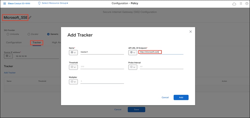
Adding a tracker to the IPsec tunnel in the Catalyst SD-WAN Manager dashboard
After establishing the tracker, create four IPsec tunnels. Configure two tunnels for HA-pair1 and another two tunnels for HA-pair2. The two HA pairs are configured as shown below:
ipsec1 ------- > HA-pair1 (active tunnel), connected through WAN link1 of CPE to Microsoft Cisco-SDWAN-WestUS-Link1
ipsec2 ------- > HA-pair1 (standby tunnel), connected through WAN link1 of CPE to Microsoft Cisco-SDWAN-EastUS-Link1
ipsec3 ------- > HA-pair2 (active tunnel), connected through WAN link2 of CPE to Microsoft Cisco-SDWAN-WestUS-Link2
ipsec4 ------- > HA-pair2 (standby tunnel), connected through WAN link2 of CPE to Microsoft Cisco-SDWAN-EastUS-Link2
Note: Users can create up to four HA pairs, enabling a total of eight IPsec tunnels.
5. Add the basic tunnel information, fill in the mandatory fields, including Interface Name, Tracker, Tunnel Source Interface (WAN Link1), the Cisco-SDWAN-EastUS-Link1 remote IP address, and Pre-shared Key (as configured in the Microsoft Entra Admin Center).
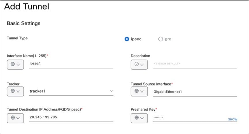
Providing basic tunnel information
6. Under Advanced Options, update the fields as required.
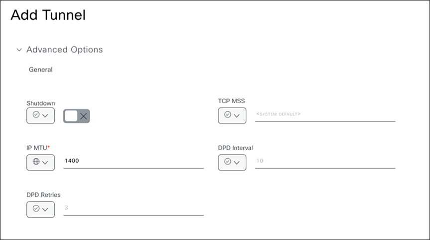
Specifying advanced options
7. For the Advanced Options IKE value, fill in the encryption parameters as configured on the IKEv2 tab of Microsoft Entra Admin Center.
Cisco SD-WAN IKE config >>>
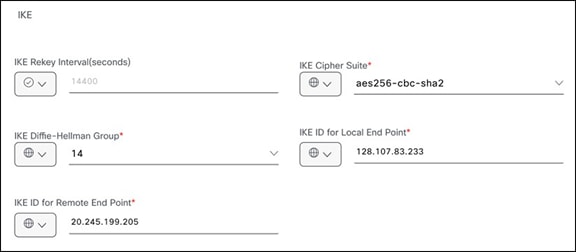
Microsoft-SSE IKE config >>>
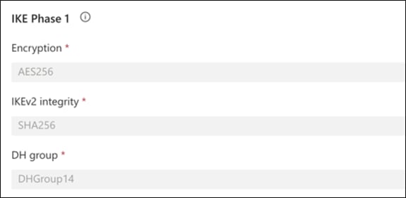
Specifying the IKE value in Catalyst SD-WAN Manager
8. For the Advanced Options IPsec value, enter the encryption parameters as configured on the IKEv2 tab of the Microsoft Entra Admin Center.
Cisco SD-WAN IPsec config >>>
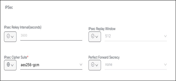
Microsoft-SSE IPSec config >>>
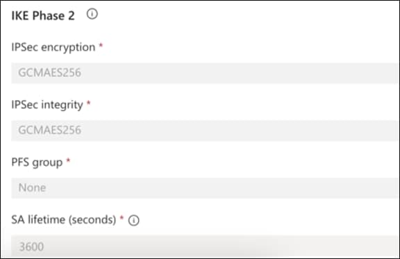
Specifying the IPsec value in Catalyst SD-WAN Manager
9. After establishing four IPsec tunnels, create two HA pairs using these four tunnels. The screen shot below shows tunnels configured that will participate in the HA pairs.
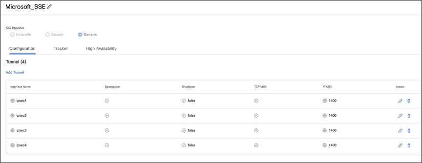
Tunnels for HA pairs
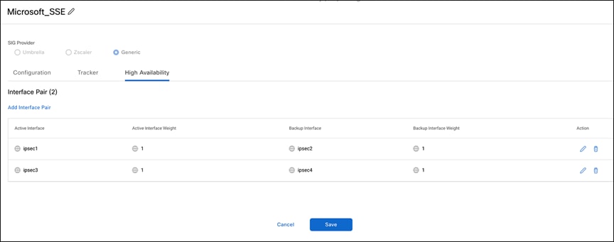
HA pairs configured
10. Attach the “Microsoft_SSE” template to the policy group and then deploy it to the device.
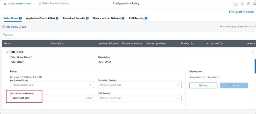
Attaching the “Microsoft_SSE” template
11. After successfully deploying the policy group on the CPE, all four tunnels and their respective trackers should be displayed.
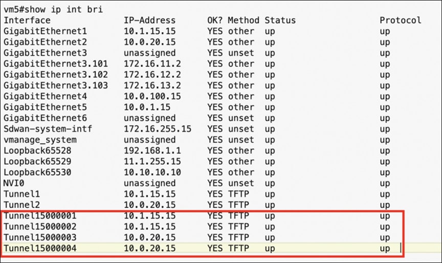
“Show interface” output from a branch edge device
Tracker status from branch edge device
vm5#show endpoint-tracker
Interface Record Name Status Address
Family RTT in msecs Probe ID Next Hop
Tunnel15000001 tracker1 Up IPv4 226 30 None
Tunnel15000002 tracker1 Up IPv4 334 33 None
Tunnel15000003 tracker1 Up IPv4 345 31 None
Tunnel15000004 tracker1 Up IPv4 662 32 None
Step 3. Configure data policy for application-based traffic redirected from CPE
On Microsoft SSE, the user has specified that only Microsoft apps will be forwarded through the tunnel on CPE. To achieve this, a data policy on the SD-WAN is needed for application-based traffic redirected toward the SIG tunnels. The SD-WAN data policy allows using the application family or subapplications as match criteria, with an action set for SSE redirection. On the Catalyst SD-WAN CPE side, configure a data policy to route traffic from the service VPN as needed. The following is a sample policy:
● Rule 1: Send all DNS traffic through Direct Internet Access (DIA) for resolution.
● Rule 2: Send Microsoft application traffic through the SIG tunnel.
● Rule 3: Send all other internet traffic through DIA.
Once the data policy is created, associate it to the controllers that will eventually be pushed to CPE.
Steps to configure a data policy
Step 1. On the Catalyst SD-WAN Manager dashboard, select Configuration > Policies > Centralized Policy, and then click Add Policy.

Adding a data policy in Catalyst SD-WAN Manager
Step 2. On the Add Policy page, create groups of interest for VPN and Site.
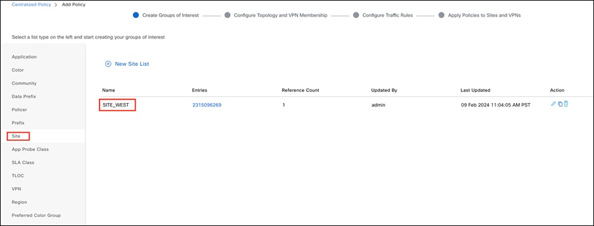
Creating a Site group of interest
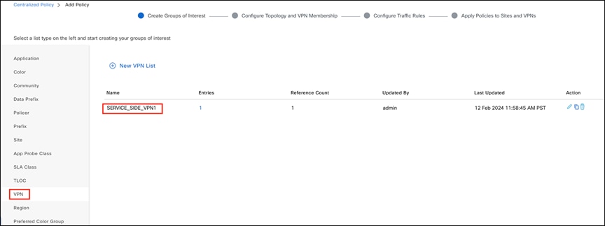
Creating a VPN group of interest
Step 3. Navigate to the Configure Traffic Rules page and select Traffic Data to configure the data policy.

Configuring traffic rules
Step 4. Add three sequences as the data policy defined above, with the three rules listed at the beginning of this section.
Below is a sample configuration for application-family-based policy rules (application family: Microsoft Apps, configured as a match condition for rule 2).
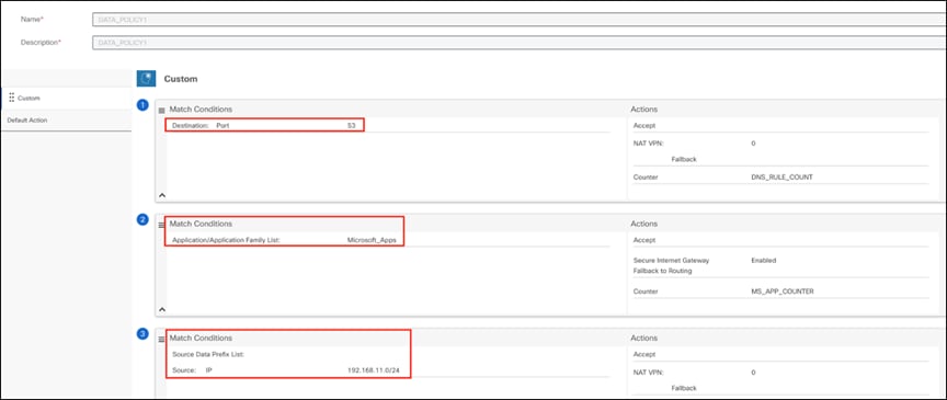
Configuring a policy rule based on application family
As another example of a more granular application, the user can configure a custom list of applications, each of which can have one or more subapplications, such as SharePoint.
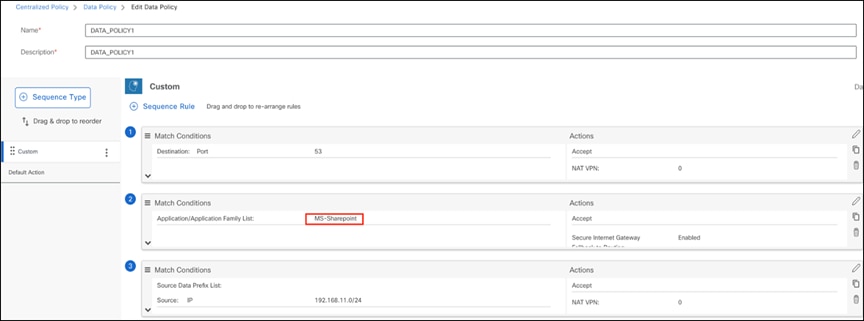
Configuring a policy rule for a subapplication
Step 5. Navigate to Apply Policies to Sites and VPNs. Click Traffic Data, and then select New Site/ Region List and VPN List. Choose the Site and VPN to apply to the data policy, and save the configuration.
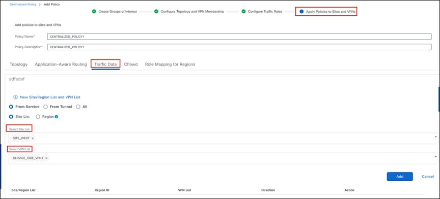
Choosing the site and VPN for the data policy
Step 6. Activate the data policy and check that the policy is configured on the branch edge device.
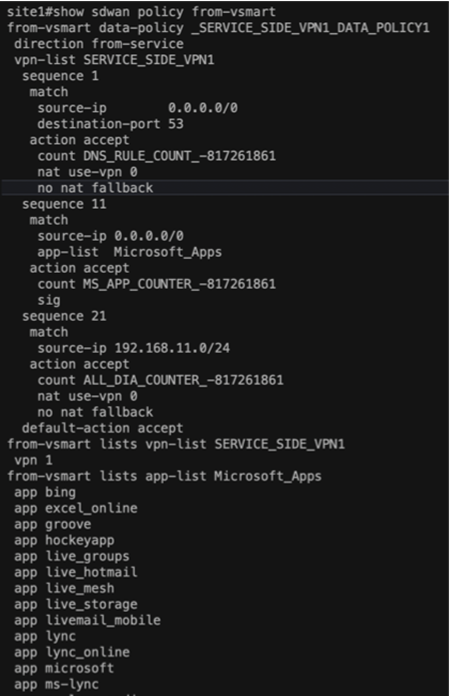

Verifying the data policy

Validating the configuration
Please visit:
● Cisco Catalyst SD-WAN Security
● Microsoft Entra Internet Access