Cisco Catalyst SD-WAN and Skyhigh Security Service Edge Integration User Guide
Available Languages
Bias-Free Language
The documentation set for this product strives to use bias-free language. For the purposes of this documentation set, bias-free is defined as language that does not imply discrimination based on age, disability, gender, racial identity, ethnic identity, sexual orientation, socioeconomic status, and intersectionality. Exceptions may be present in the documentation due to language that is hardcoded in the user interfaces of the product software, language used based on RFP documentation, or language that is used by a referenced third-party product. Learn more about how Cisco is using Inclusive Language.
The integration of Cisco Catalyst™ SD-WAN with Skyhigh Security Service Edge (SSE) cloud empowers customers to bolster the security of their branch internet traffic through seamless redirection. By harnessing Cisco® Catalyst SD-WAN Secure Internet Gateway (SIG) templates, the implementation process becomes efficient and straightforward. These templates offer an intuitive workflow for comprehensive end-to-end configuration, encompassing critical features such as Point of Presence (POP) availability, application health checks, weighted load balancing, and data policy enforcement. With this integration, users can effortlessly specify the desired redirection of branch traffic to the Skyhigh SSE. It's worth noting that the integration has undergone rigorous testing and validation within Cisco, ensuring seamless compatibility and reliable performance.
This document serves as a technical and configuration guide for successfully integrating Skyhigh SSE and Cisco Catalyst SD-WAN, utilizing the capabilities provided by Cisco Catalyst SD-WAN Manager Release 20.9 and Cisco IOS® XE SD-WAN WAN Edge Release 17.9. It includes practical examples demonstrating how to provision a new service to integrate Skyhigh SSE and Cisco Catalyst SD-WAN IPsec tunnel using the SIG feature template implementation. IPsec primary and secondary tunnels are established to Skyhigh SSE for Direct Internet Traffic (DIA).
The following Cisco Catalyst SD-WAN and Skyhigh SSE use cases are covered within this document:
● Dual WAN Edge design with one active tunnel per WAN Edge
● Dual WAN Edge design with one active/standby tunnel per WAN Edge
● Dual WAN Edge design with two active/active Equal-Cost Multi-Path Routing (ECMP) tunnel deployment per WAN Edge
● Utilization of centralized data policy for traffic redirection
Cisco Catalyst SD-WAN - Skyhigh network topology with active backup tunnels to Skyhigh POPs
Cisco Catalyst SD-WAN SSE Integration with Skyhigh for Secure Internet Access
Use case
This integration guide serves as a reference for customers who run the Skyhigh SSE solution alongside the Cisco Catalyst SD-WAN solution. It is designed for scenarios where branch users require internet or SaaS application access that needs to be inspected and secured by the Skyhigh SSE solution.
Pre-requisites and Validated Environment
● Skyhigh Security Cloud Version 6.4.2
● Cisco Catalyst SD-WAN Manager Release 20.9, Cisco Catalyst SD-WAN Validator Release 20.9, Cisco Catalyst SD-WAN Controller Release 20.9, Cisco Catalyst SD-WAN C8kv Edge Release 17.9
● Knowledge of Cisco Catalyst SD-WAN configuration and features
Supported Hardware
● ISR 4461, 4451, 4431, 4351, 4331, 4321, 4221X, 4221, CSR, ISRv, and ISR 1K
● Catalyst® 8500L, 8300, 8200, and 8000V
Sample topology diagram with SD-WAN and Skyhigh network
The following tests have been conducted with an emphasis on ensuring redundancy.

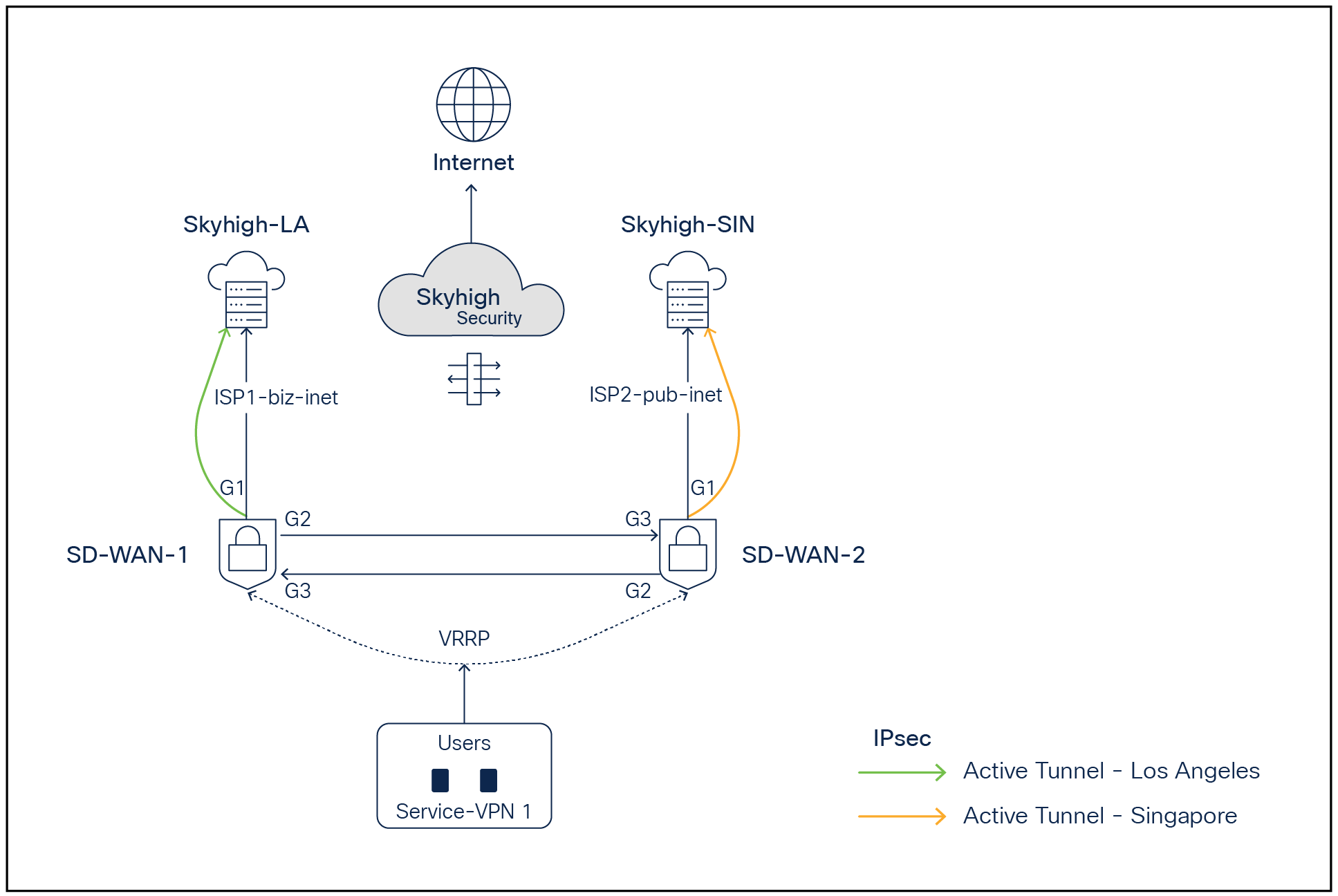
SD-WAN - Skyhigh network topology with active backup tunnels to Skyhigh POPs
In the above topology, two branch routers, SD-WAN-1 and SD-WAN-2, are connected to Skyhigh SSE Datacenter locations (Los Angeles and Singapore) using redundant ISPs (Biz-internet and public-internet colors). The Transport Locator (TLOC) extension feature has been used to provide cross-ISP connectivity from both routers. The Service VPN can be redundantly configured using Layer 2 protocols including Virtual Router Redundancy Protocol (VRRP) or Layer 3 routing protocols such as Border Gateway Protocol (BGP) or any other supported protocols. The architecture provides redundancy at the tunnel, data center, ISP, and router levels.
Redundancy Connectivity Matrix
In the above diagram, ISP1 is tied with the LA location, and ISP2 is tied with the Singapore location.
| Router |
ISP-Color |
Skyhigh SSE POP |
| SD-WAN-1 |
Biz-internet (Gig1) |
LA (Active Tunnel) |
| SD-WAN-1 |
Public-internet (Gig2) using TLOC extension from SDWAN2 |
LA (Backup Tunnel) |
| SD-WAN-2 |
Pub-internet (Gig1) |
Singapore (Backup Tunnel) |
| SD-WAN-2 |
Biz-internet (Gig2) using TLOC extension from SD-WAN1 |
Singapore (Active Tunnel) |
Note: The TLOC extension feature enables a WAN Edge router to communicate over the WAN transport connected to the adjacent WAN Edge router through a TLOC extension interface, allowing for redundancy on the transport side.
Overview of Configuration Steps
Step 1: Set up locations on the Skyhigh SSE cloud platform under web-gateway
Step 2: Set up tunnels on Cisco Catalyst SD-WAN Manager platform using SIG templates
Step 3: On SD-WAN Manager, set up policy to route traffic to Skyhigh SSE
Step 4: Verify tunnel operation on Cisco Catalyst SD-WAN Manager and CLI
Step 5: Verify web traffic on the Skyhigh SSE cloud platform
Configuration Process in Detail
Step 1: Skyhigh location setup
Navigate to Setup > Infrastructure > Web Gateway setup.
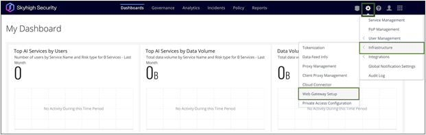
Skyhigh Dashboard
IPsec Tunnel Setup:
Under Secure Web Gateway Setup, go to Configure Locations > New Location.
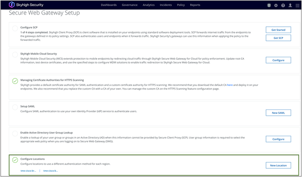
Skyhigh Web Gateway Setup
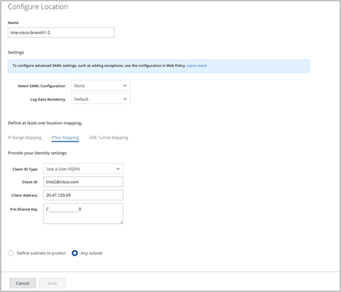
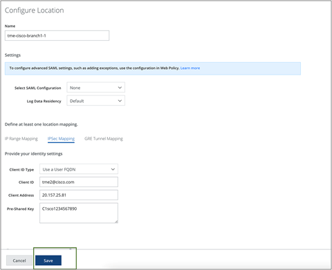
Configure Location attributes:
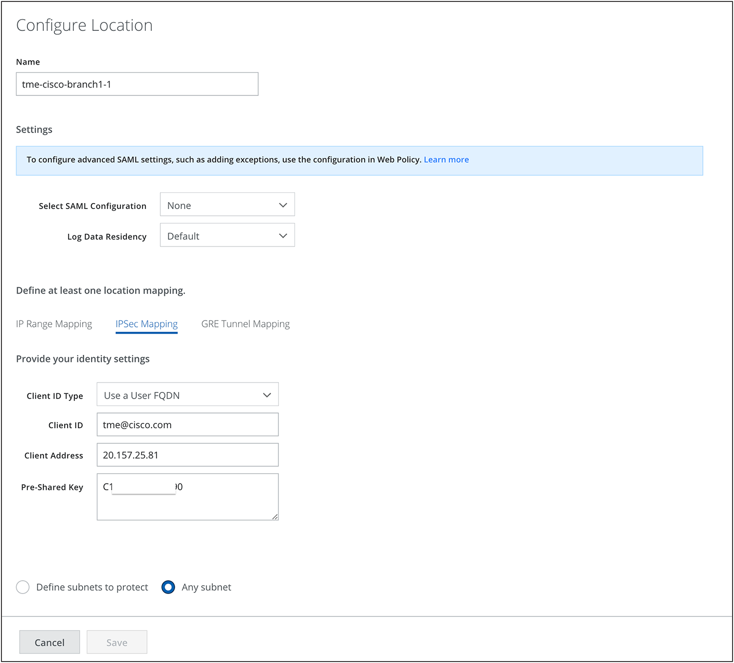
Skyhigh location configuration
Location Mapping: IPsec Mapping (in this phase, only IPsec is validated)
Note: Skyhigh supports both IPsec and Generic Routing Encapsulation (GRE).
Client ID Type: Can be based on IPs, Fully Qualified Domain Names (FQDNs) or emails and can be behind Network Address Translation (NAT)
The Client ID should be provided with the corresponding Client ID type. Follow the article for reference.
Client ID = email (in this case)
Client address = ISP outgoing IP used to build tunnels
Note: Each Skyhigh location requires a unique client address to create location, meaning each location is tied to the ISP’s outgoing IP.
Pre-shared key= Use any secure key
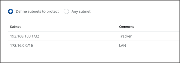
Choose Any subnet or Define protected subnets that need to be secured on the branch side.
Using a similar process, add the Second Skyhigh location:
Skyhigh location configuration
Configure the rules on Skyhigh as required for Web policy:
Refer to the Skyhigh web policy page for further details.
Skyhigh Web Policy setup
Step 2: Catalyst SD-WAN Manager IPsec tunnel setup
SIG Templates are used for connectivity, providing multiplexing capability to carry multiple Service VPN (VRF) traffic within the same set of tunnels. They are recommended by Cisco for any SIG connectivity.
To set up tunnels using SIG templates, navigate to the Catalyst SD-WAN Manager Dashboard, select Configuration > Templates > Feature Template, and create a SIG template.
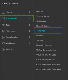
Cisco SD-WAN Manager Dashboard
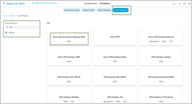
Cisco SD-WAN SIG Feature Template configuration
SIG Provider:
In the SIG Template, select the Generic Tunnel option.
(Only template-based tunnel is supported at this point)
Configuring Layer 7 Health Checks to Monitor Tunnels:
Create a tracker to ensure the health of the tunnel. In this example, "cisco.com" is used as the endpoint address, but any internet HTTP destination can be used. Please note that HTTPS destinations are not supported. RFC 1918 IP is supported as a tracker source.
Note: Layer 7 Health Checks are used to monitor the health of tunnels toward the SIG using trackers attached to the tunnels. These trackers facilitate automatic failover to back up tunnels based on tunnel health. Failover occurs when SLA parameters are not met or when the SIG tunnel is down.
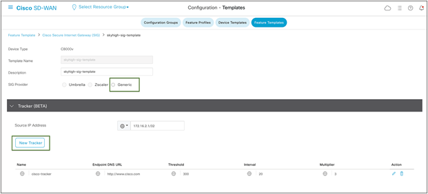
Cisco SD-WAN tracker configuration in SIG template
Add IPsec Tunnel:
During the tunnel creation, select tunnel type IPsec. Then from the dropdown menu, select the tracker created in the previous step from the dropdown menu.
Select IPsec source interface.
Tunnel destinations can be found using nslookup. Refer to this article by Skyhigh.
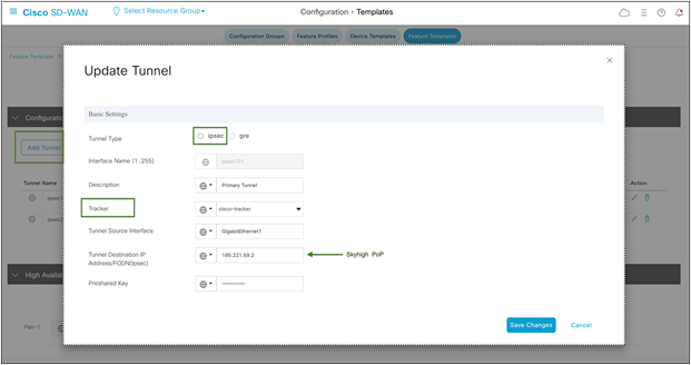
Cisco SD-WAN IPsec tunnel configuration in SIG template
Advanced options:
In the IKE ID for the local end point, use the Client ID specified in step 1 during the Skyhigh location creation.
Ensure that the IKE and IPsec cipher suites are part of supported ciphers by Skyhigh.
Please refer to this Skyhigh article for Skyhigh IKE/IPsec settings.
Note: In the advanced options for tunnel creation, the default is NULL SHA1. Change it to AES 256.
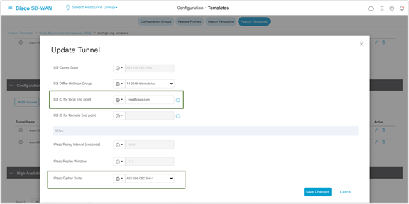
Cisco SD-WAN IPsec tunnel advanced options configuration
Secondary Tunnel:
Following the same steps as above, create the secondary tunnel and utilize the IP address of the other Skyhigh POP.
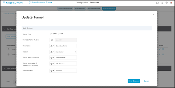
Cisco SD-WAN IPsec tunnel configuration for backup tunnel
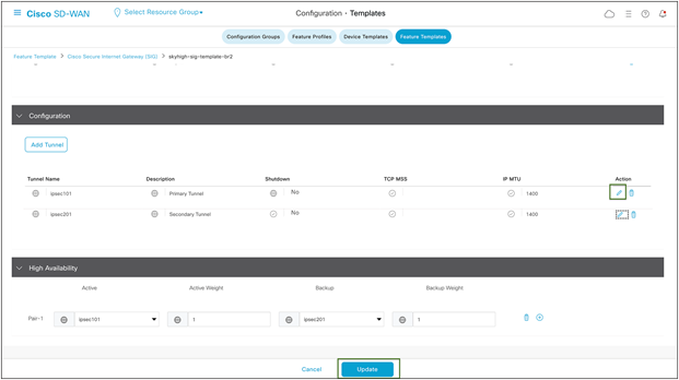
HA Configuration:
Once the two tunnels are created as shown below, proceed to HA configuration using these two tunnels. This step ensures that traffic automatically fails over to the secondary tunnel if the primary tunnel goes down.
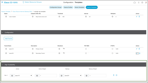
Cisco SD-WAN active/backup high-availability configuration
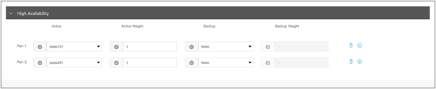
ECMP Tunnels:
To configure ECMP tunnels, choose “None” under the backup of Pair-1, and configure Pair-2 with secondary tunnel as the active tunnel, as shown in figure 14 below.
Cisco SD-WAN IPsec ECMP configuration
Note: The Cisco solution offers a capability of four ECMP active and four backup tunnels, which can be configured using loopbacks with same outgoing ISP IP and location combination. However, to have multiple ECMP tunnels, multiple locations must be configured using unique public IP on the Skyhigh portal. So, four unique public IP addresses are required for configuring four ECMP active tunnels.
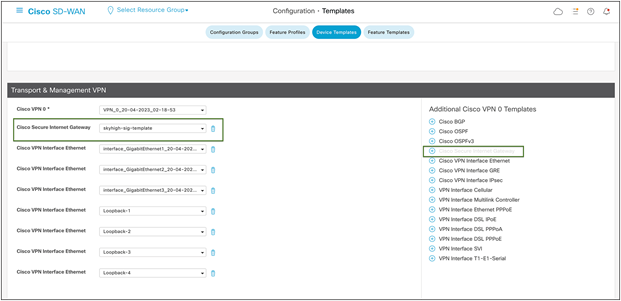
Add SIG Feature Template to the Device Template:
Navigate to the Catalyst SD-WAN Manager Dashboard, select Configuration > Templates > Device Templates, and edit the device template.
Add Cisco Secure Internet Gateway template from right end, as shown in figure 15.
Cisco SD-WAN device template configuration
No variables need to be defined, so click Update>“Next” after this step, then proceed to “Configure Devices.”
Catalyst SD-WAN Manager should return a success message once the configuration process is complete.
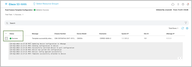
Cisco SD-WAN configuration status
Step 3: Setup policy-based traffic redirection
Traffic to SIG
The traffic from the service VPN can be redirected to SIG tunnels in two ways.
● Using a static default route to the service SIG
● Using centralized data policy to redirect to the service SIG, in case specific applications or traffic need to be redirected for secure internet/SAAS access
For further information on the SIG template and redirection policy, refer to this guide.
Note: Skyhigh SSE (web gateway) can only process secure web (http(s)) traffic. Therefore, Internet Control Message Protocol (ICMP), and Domain Name System (DNS) traffic should not be sent through the tunnels toward Skyhigh SSE. In this case, data policy can be used to redirect web traffic to Skyhigh.
Navigate to the Catalyst SD-WAN Manager Dashboard, select Configuration > Policies > Centralized Policy.
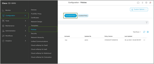
Cisco SD-WAN policy configuration
Navigate to Centralized Policy and configure a traffic data policy to match on ports 80 and 443. Redirect all web to Skyhigh SSE using the tunnels configured above. Apply the policy to the Service VPN and to sites configured with tunnels.
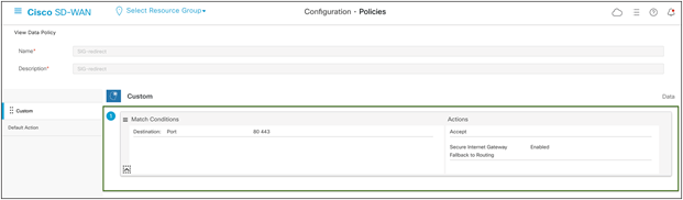
Cisco SD-WAN custom data policy configuration
Note: The default action is drop for traffic data policy, so change that to Accept.
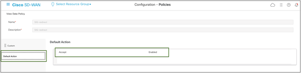
Cisco SD-WAN default data policy configuration
Step 4: Verify Tunnel operation on Cisco Catalyst SD-WAN Manager and CLI
In the SD-WAN Manager GUI:
Under Monitor navigate to Devices -> WAN Edge router ellipsis -> Real Time
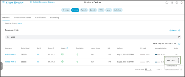
Cisco SD-WAN device monitoring
Under Applications > Interface, click Real Time at the top right of the chart.
Then, select the interface on the right-hand side of the chart to view specific interface activity.
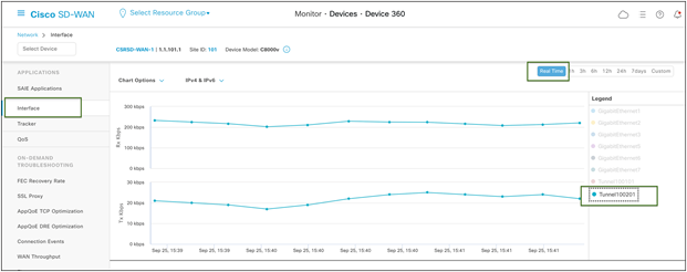
Cisco SD-WAN device 360 Real Time Monitor
If the interface is missing from the graph, scroll down past the chart to see the complete list of interfaces. Click the checkbox on the left for the interface to display on the chart. You can view the state and statistics of all device interfaces from this list.
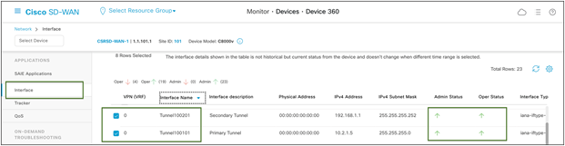
Cisco SD-WAN Real Time device interface monitoring
Verify Tunnel Operation Using CLI:
Use the show sdwan secure-internet-gateway tunnels command to view SIG tunnel status to Skyhigh SSE
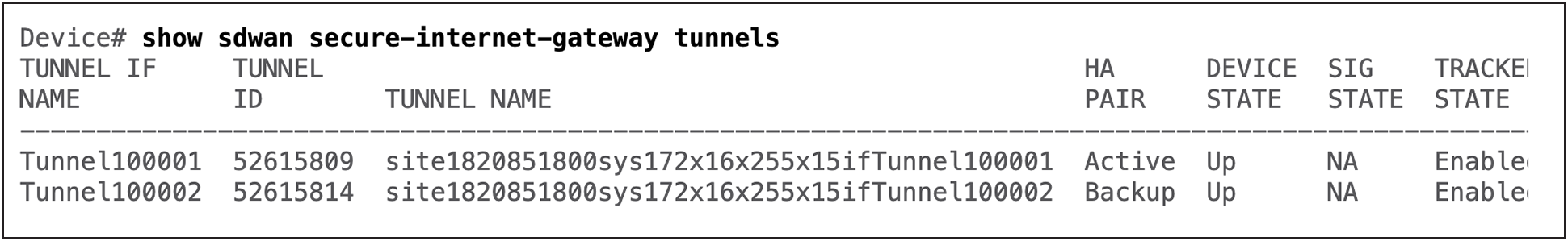
Cisco Edge device CLI output
Step 5: Verify web traffic on Skyhigh SSE cloud platform
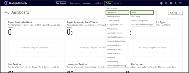
Navigate to Analytics > Web > Web Traffic on the Skyhigh dashboard.
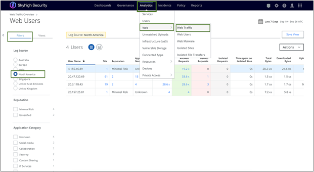
Skyhigh Web Traffic analytics
The Web Traffic page offers an overview of organization's traffic data, which can be used for analysis or reporting. It includes aggregated data on visits, website and application names, requests (hits), access status (allowed or denied), and data transfer (bytes uploaded and downloaded). For more details on filtering and sorting web traffic refer to this article.
Below are a few deployment models in the case of two SD-WAN edge devices, two ISPs, and two Skyhigh locations.
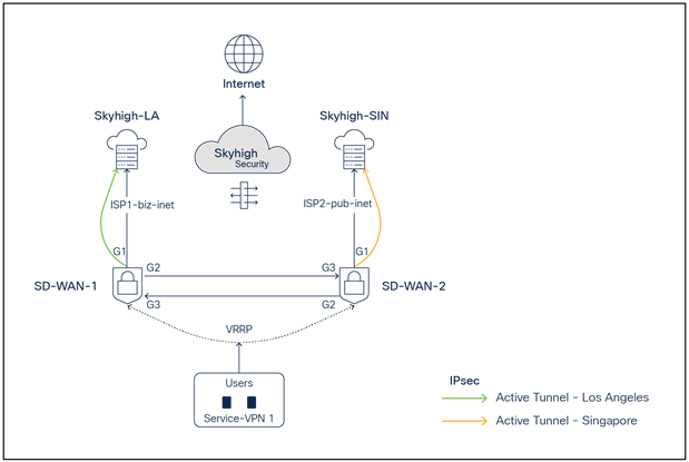
Deployment model 1: One active IPsec tunnel per WAN Edge
SD-WAN and Skyhigh topology diagram with one active IPsec tunnel per Edge
● SD-WAN-1 is connected to the Skyhigh SSE Datacenter location LA using ISP1
● SD-WAN-2 is connected to the Skyhigh SSE Datacenter location SIN using ISP2
● Active IPsec tunnels are established from SD-WAN-1 and SD-WAN-2 to LA and SIN, respectively
● Service VPN is redundantly configured with VRRP
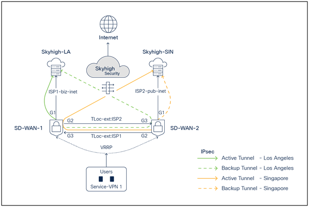
Deployment model 2: One active/backup IPsec tunnel per WAN Edge
SD-WAN and Skyhigh topology diagram with one active - one backup IPsec tunnel per Edge
● SD-WAN-1 is connected to the Skyhigh SSE Datacenter location LA using ISP1 and ISP2 (TLOC extension)
● SD-WAN-2 is connected to the Skyhigh SSE Datacenter location SIN using ISP1 (TLOC extension) and ISP2
● Active/Backup IPsec tunnels are established from SD-WAN1 router to LA and from SD-WAN-2 to SIN
● Service VPN is redundantly configured with VRRP
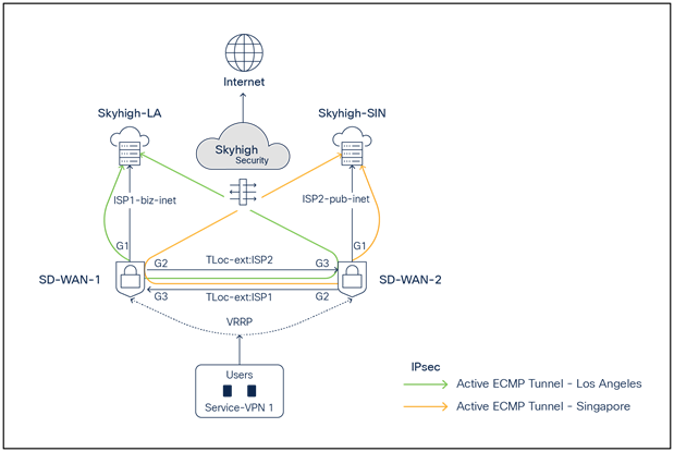
Deployment model 3: Two active/active ECMP IPsec tunnels per WAN Edge
SD-WAN and Skyhigh topology diagram with two active ECMP IPsec tunnels per Edge
● SD-WAN-1 is connected to the Skyhigh SSE Datacenter location LA using ISP1 and ISP2 (TLOC extension)
● SD-WAN-2 is connected to the Skyhigh SSE Datacenter location SIN using ISP1 and ISP2 (TLOC extension)
● Active/Active ECMP IPsec tunnels are established from SD-WAN 1 to LA and from SD-WAN 2 to Singapore
● Service VPN is redundantly configured with VRRP
Skyhigh Web Gateway Configuration Modification Procedure
Once changes are made on the web gateway, save, and publish the changes.
Note: To make changes to configurations on Skyhigh UI, it is recommended to first shut down tunnels on the SD-WAN edge device and then perform the changes. Once changes are completed on the Skyhigh UI, enable the tunnels on the SD-WAN Edge. This will provide immediate implementation of any changes.
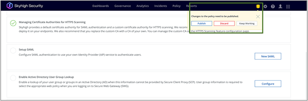
Skyhigh location configuration changes
Cisco Catalyst SD-WAN Manager Configuration Modification Procedure
Example: To change IKE ID on IPsec tunnel101
Go to Configuration > Templates > Feature Template. Click on the ellipsis icon to edit the template.
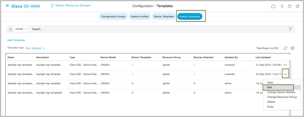
Edit the tunnel configuration, and save it as shown in figures 29 and 30 below by clicking Update and Save Changes.
Cisco SD-WAN device template configuration changes
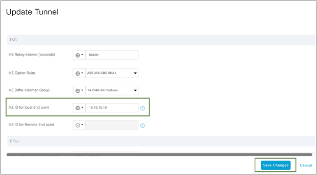
Cisco SD-WAN IPsec tunnel advanced configuration changes
Update and click Next.
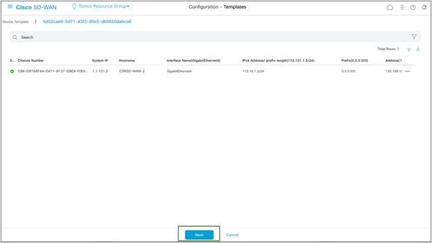
Cisco SD-WAN device provisioning with changes
Config preview and config differences can be viewed on this page.
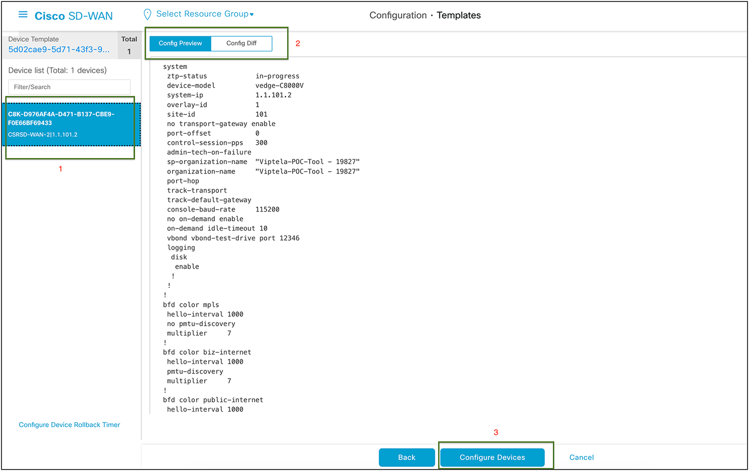
Cisco SD-WAN config preview
Config difference can be viewed in two ways: side by side or inline.
This is an inline view with changes highlighted in red and green. Once validated, click Configure Devices.
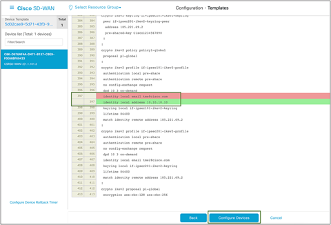
Cisco SD-WAN config difference
Once the Configuration is deployed to SD-WAN Edge, the status returns as Success.

Cisco SD-WAN configuration status
In conclusion, the integration of Cisco Catalyst SD-WAN with Skyhigh SSE offers an efficient and secure solution for branch internet traffic. The seamless redirection and comprehensive features enhance network performance while ensuring robust cybersecurity measures. This validated guide serves as a valuable reference for customers implementing the Skyhigh Secure Service Edge solution alongside Cisco Catalyst SD-WAN, providing flexibility and reliable performance.
Try it now
Take the first step in modernizing your WAN architecture. Contact us for a free consultation on integrating your Cisco Catalyst SD-WAN with Skyhigh Security.
Please visit: