Secure Access Service Edge (SASE) With Viptela SD-WAN Design Guide
Available Languages
Bias-Free Language
The documentation set for this product strives to use bias-free language. For the purposes of this documentation set, bias-free is defined as language that does not imply discrimination based on age, disability, gender, racial identity, ethnic identity, sexual orientation, socioeconomic status, and intersectionality. Exceptions may be present in the documentation due to language that is hardcoded in the user interfaces of the product software, language used based on RFP documentation, or language that is used by a referenced third-party product. Learn more about how Cisco is using Inclusive Language.
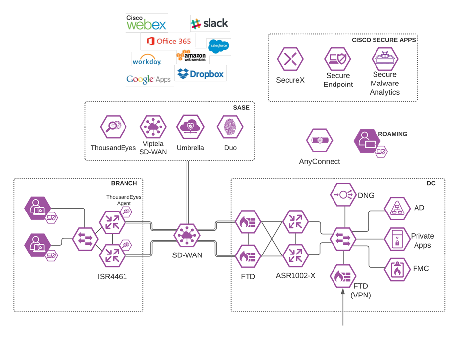
Cisco SASE design guide with Viptela covers the following components:
● Cisco Viptela SD-WAN
● Cisco Umbrella Secure Internet Gateway
◦ DNS Security
◦ Secure Web Gateway
◦ Cloud Delivered Firewall including IPS
◦ Data Loss Prevention
◦ Remote Browser Isolation
● Cisco Secure Access by Duo
◦ Multi-factor authentication
◦ VPNless access to private applications (Duo Network Gateway)
◦ Single sign on
● Cisco Remote Access VPN
◦ Cisco AnyConnect
◦ Cisco Firepower Threat Defense
● Cisco Secure Endpoint
● Cisco ThousandEyes
● Cisco SecureX
◦ Visibility Dashboard
Cisco SASE design guide with Viptela does not cover the following topics:
● The Viptela scope has been limited to basic WAN connectivity and the creation of IPsec tunnels to Umbrella from a high availability pair. Capabilities such as quality of service, TCP flow optimization or service chaining have not been evaluated in this design
● Security has been assumed to exist in the Data Center, but the level of security, and the use of those tools have not been included in this design guide
● Cisco Secure Endpoint has been included in its most basic form. Creation of custom policies is out of scope for this guide
● Cisco Secure Malware Analytics, the file sandboxing engine used by Cisco Secure Endpoint, is not in scope for this design guide
● Laptops and desktop clients are the only sources of traffic. No smartphones or internet of things devices were used in the creation of this guide
Today’s workforce expects seamless access to applications wherever they are, on any device. It is now common practice to provide remote employees with direct access to cloud applications such as Office 365 and Salesforce with additional security. The need for cloud-delivered security service expands daily as contractors, partners, IoT devices and more each require network access. IT needs to protect users and devices as if they were located at a corporate office or branch. Each requires secure access to applications and must now be treated as a ‘branch of one’.
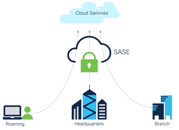
High level SASE Architecture
In this new paradigm, IT requires a simple and reliable approach to protect and connect with agility. This is forcing a convergence of network and security functions closer to users and devices, at the edge—and is best delivered as a cloud-based, as-a-service model called secure access service edge (SASE).
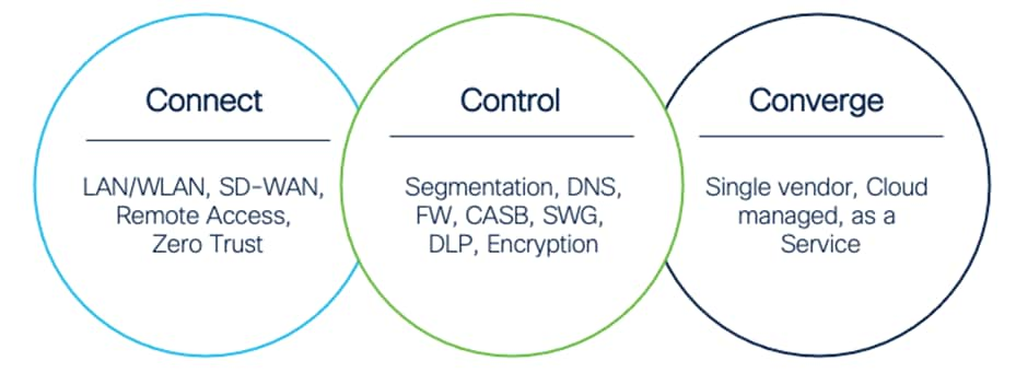
Three Cs for SASE
The SASE architecture has three core components:
● Connect – Unleash your workforce by delivering a seamless connection to applications in any environment from any location
● Control – Simplify security, streamline policy enforcement, and increase threat protection by combining multiple functions into a single, cloud-native service
● Converge – Unite security and networking through a flexible, integrated approach that meets multi-cloud demands at scale
For a full breakdown of the architecture, see the Cisco SASE Architecture Guide.
In the Cisco SASE Architecture guide, the concept of SAFE business flows was introduced. Cisco SAFE uses the concept of business flows to simplify the analysis and identification of threats, risks, and policy requirements for effective security. This enables the selection of very specific capabilities necessary to secure them.
This design guide addresses the following business flows for a SASE network:
● An unmanaged device accessing business critical SaaS applications
● A managed device browsing the public Internet, such as researching product information
● An unmanaged device accessing corporate applications that are publicly accessible
● A managed device accessing corporate applications that are not publicly accessible
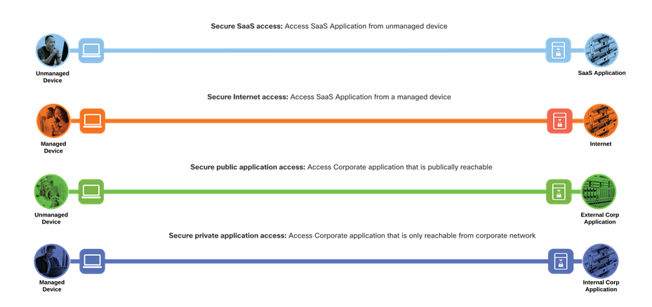
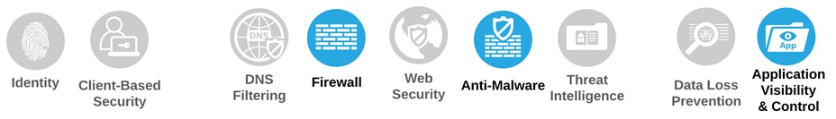
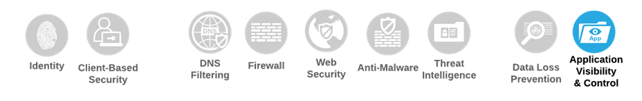
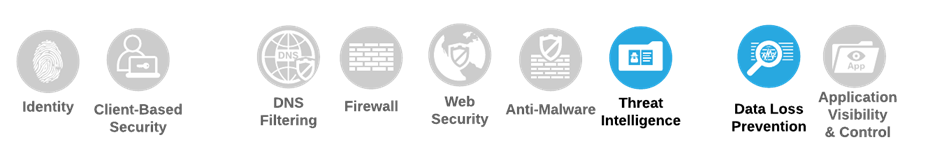
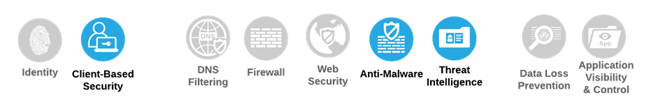
SASE Business Flows
Not all business flows have the same requirements. Some use cases are subject to a smaller attack vector and therefore require less security to be applied. Some have larger and multiple vectors and require more. Evaluating the business flow by analyzing the attack surfaces provides the information needed to determine and apply the correct capabilities for flow specific and effective security. This process also allows for the application of capabilities to address risk and administrative policy requirements.
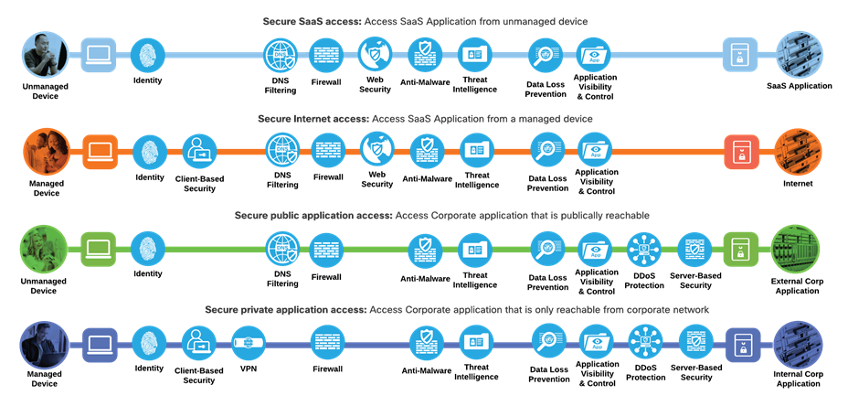
SASE Business Flows with required capabilities
Cisco SASE Architecture
Viptela SD-WAN with Umbrella SIG
Software-defined WAN (SD-WAN) is a suite of features designed to allow the network to dynamically adjust to changing WAN conditions without the need for manual intervention by the network administrator. By providing granular control over how certain traffic types respond to changes in WAN availability and performance, SD-WAN can ensure optimal performance for critical applications and help to avoid disruptions of highly performance-sensitive traffic, such as VoIP. Additionally, SD-WAN can be a scalable and often much cheaper alternative to traditional WAN circuits like multiprotocol label switching (MPLS) lines. Cisco provides a flexible deployment architecture to extend SD-WAN to any environment. Whether you deploy your product in the cloud or on-premises, Cisco SD-WAN automatically discovers, authenticates, and provisions both new and existing devices.
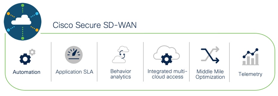
Cisco SD-WAN
Enabling direct internet access (DIA) from the branch is simplified with Cisco SD-WAN technology. The Cisco SD-WAN and Umbrella integration enables you to infuse effective cloud security throughout your SD-WAN fabric. Cloud security can be deployed to thousands of branches in a matter of minutes, instantly gaining protection against threats on the internet.
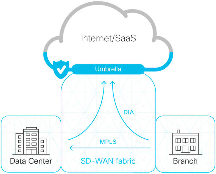
Viptela/Umbrella Integration
Cisco AnyConnect is unified security endpoint agent that delivers multiple security services to the roaming workforce.
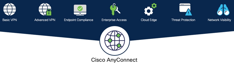
Cisco AnyConnect Secure Mobility Client
Cisco AnyConnect not only provides VPN access through Secure Sockets Layer (SSL) and IPsec IKEv2 but also offers enhanced security through various built-in modules. Modules used in this guide include:
● Off-Network Protection – Cisco Umbrella Roaming module protects devices while not connected to a trusted network. This module forces all traffic through Umbrella SIG, enabling consistent policies to be applied to users on and off net
● AMP Enabler – Cisco AnyConnect AMP Enabler is used as a medium for deploying Cisco Secure Endpoint, formerly Advanced Malware Protection (AMP). This approach provides the roaming workforce with an additional security agent that detects potential malware threats, allowing for removal of said malware and the quarantine of devices from doing further harm in the network when they try to connect back to the enterprise
For information on additional AnyConnect features, such as the ability to do NetFlow analysis for the roaming workforce, see Cisco AnyConnect Secure Mobility Client.
Duo Network Gateway (DNG) allows users to access on-premises websites, web applications, and SSH servers without having to worry about managing VPN credentials, while also adding security with Duo MFA (discussed in the Control section below).
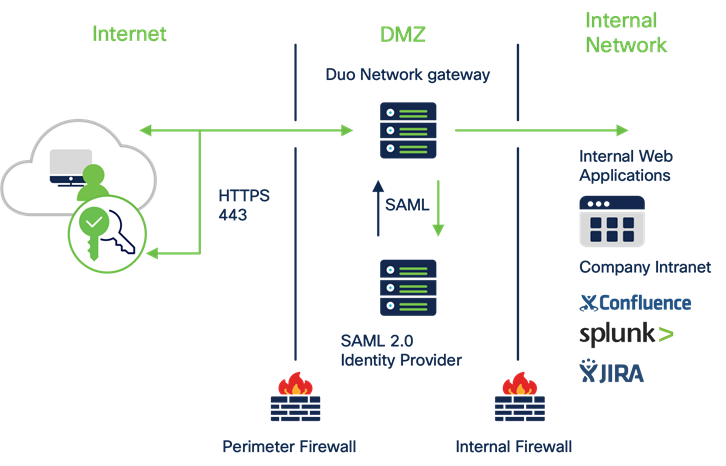
Cisco Duo Network Gateway
DNG gives you granular access control per web application, set of SSH servers, and user groups. You can specify different policies to make sure only trusted users and endpoints are able to access your internal services. For example, you can require that SharePoint users complete two-factor authentication at every login, but only once every seven days when accessing Confluence. Duo checks the user, device, and network against an application's policy before allowing access to the application.
With the advent of the cloud era, network architectures designed to provide robust connectivity to a corporate data center is increasingly inefficient and must evolve. Most of the network traffic today occurs either within the data center itself (East-West traffic) or from an organization’s various locations to the cloud via the Internet (North-South traffic). As a result, backhauling network traffic from remote or branch locations over MPLS wide-area network (WAN) links, or roaming user traffic over virtual private network (VPN) connections, is no longer an efficient or viable option. Organizations are increasingly providing DIA broadband links for their remote, branch, and roaming users to access their SaaS applications without the slow performance and latency associated with backhauling traffic to a corporate office with a single security stack. To alleviate the inconvenience of separately managing security settings at each branch location, Umbrella Secure Internet Gateway (SIG) provides a cloud managed solution.
Cisco Umbrella SIG unifies multiple functions in a single solution that traditionally required a set of on-premises security appliances (firewalls, proxies, gateways) or single function cloud-based security solutions. Umbrella combines secure web gateway (SWG), firewall, DNS-layer security, cloud access security broker (CASB) functionality, remote browser isolation (RBI), data loss prevention (DLP), plus interactive threat intelligence in one cloud-delivered service.
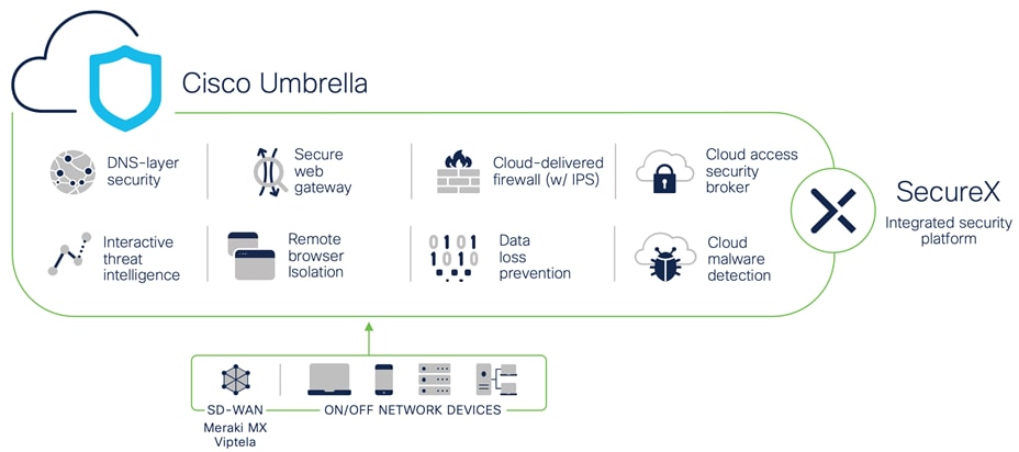
Umbrella
Brief summaries of key Cisco Umbrella functions:
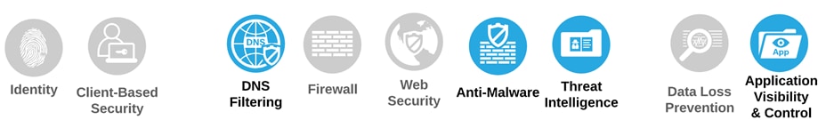
SAFE Capability - DNS Filtering
By enforcing security at the DNS and IP layers, Umbrella blocks requests to malicious and unwanted destinations before a connection is even established — stopping threats over any port or protocol before they reach your network or endpoints. Highlights include:
● The visibility needed to protect internet access across all network devices, office locations, and roaming users
● Detailed reporting for DNS activity by type of security threat or web content and the action taken
● Ability to retain logs of all activity for as long as needed
● Fast rollout to thousands of locations and users to provide immediate return on investment
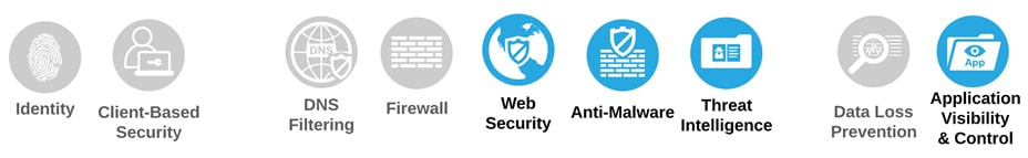
SAFE Capability – Web Security
Umbrella includes a cloud-based full proxy that can log and inspect all your web traffic for greater transparency, control, and protection. IPsec tunnels, PAC files and proxy chaining can be used to forward traffic for full visibility, URL and application-level controls, and advanced threat protection. Highlights include:
● Content filtering by category or specific URLs to block destinations that violate policies or compliance regulations
● The ability to efficiently scan all uploaded and downloaded files for malware and other threats using the Cisco Secure Endpoint (formerly Cisco AMP) engine and third-party resources
● Cisco Secure Malware Analytics (formerly Threat Grid) rapidly analyzes suspicious files
● File type blocking (e.g., block download of .exe files)
● Full or selective SSL decryption to further protect your organization from hidden attacks and time-consuming infections
● Granular app controls to block specific user activities in select apps (e.g., file uploads to Dropbox, attachments to Gmail, post/shares on Facebook)
● Detailed reporting with full URL addresses, network identity, allow or block actions, plus the external IP address
Cloud-Delivered Firewall (CDFW)
Web Capability - Firewall
The Umbrella CDFW provides visibility and control for traffic that originated from requests going to the internet, across all ports and protocols. Highlights include:
● Deployment, management and reporting through the Umbrella single, unified dashboard
● Customizable policies (IP, port, protocol, application and IPS policies)
● Layer 3 / 4 firewall to log all activity and block unwanted traffic using IP, port, and protocol rules
● Layer 7 application visibility and control to identify and control access to thousands of applications
● Intrusion Prevention System (IPS) to examine network traffic flows and prevent vulnerability exploits with an added layer of threat prevention using SNORT 3 technology
● Detection and blocking of vulnerability exploitation
● Scalable cloud compute resources eliminate appliance capacity concerns Cisco Talos threat intelligence to detect and block more threats
Cloud Access Security Broker (CASB)
SAFE Capability – Application Visibility & Control
Umbrella helps expose shadow IT by detecting and reporting on cloud applications in use across your environment. Insights can help manage cloud adoption, reduce risk, and block the use of offensive or inappropriate cloud applications. Highlights include:
● Reports on vendor category, application name, and volume of activity for each discovered app
● App details and risk information such as web reputation score, financial viability, and relevant compliance certifications
● Cloud malware detection to detect and remove malware from cloud-based applications and ensure that applications remain malware-free
● Ability to block/allow specific apps
● Tenant restrictions to control the instance(s) of SaaS applications that all users or specific groups/individuals can access.
SAFE Capability – Data Loss Prevention
As more companies move toward cloud-based services, company data becomes more vulnerable to both malicious exfiltration and unintentional misuse by inexperienced users. Umbrella DLP analyzes data in-line to provide visibility and control over sensitive data leaving your organization. Highlights include:
● Easy enablement as part of Umbrella secure web gateway
● 80+ built-in content classifiers including personally identifiable information (PII), payment card industry (PCI), and personal health information (PHI)
● Content classifiers are customizable with threshold and proximity to tune and reduce false positives
● Create user-defined dictionaries with custom phrases (such as project code names)
● Detection and reporting on sensitive data usage and drill-down reports to help identify misuse
● Inspection of cloud application and web traffic content and enforcement of data policies
Remote Browser Isolation (RBI)
SAFE Capability – Remote Browser Isolation as a feature of Web Security
By isolating web traffic from the user device and the threat, Umbrella Remote Browser Isolation (RBI) delivers an extra layer of protection to the Umbrella secure web gateway so that users can safely access risky websites. Highlights include:
● Isolation of web traffic between user device and browser-based threats
● No performance impact on end users
● Protection from zero-day threats
● Granular controls for different risk profiles
● Rapid deployment without changing existing browser configuration
● On-demand scale to easily protect additional users on all devices, browsers, and operating systems
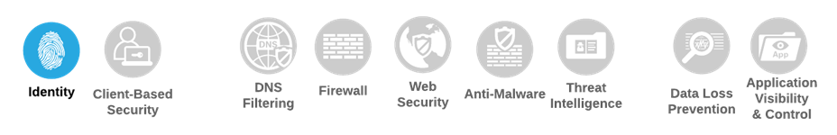
SAFE Capability - Identity
Multi-factor authentication (MFA) from Cisco's Duo protects your applications by using a second source of validation, like a phone or token, to verify user identity before granting access. The modern workforce is more mobile than ever before. Users and devices can connect from anywhere — so companies must protect them everywhere. A zero-trust security model establishes trust in users and devices through authentication and continuous monitoring of each access attempt, with custom security policies that protect every application.
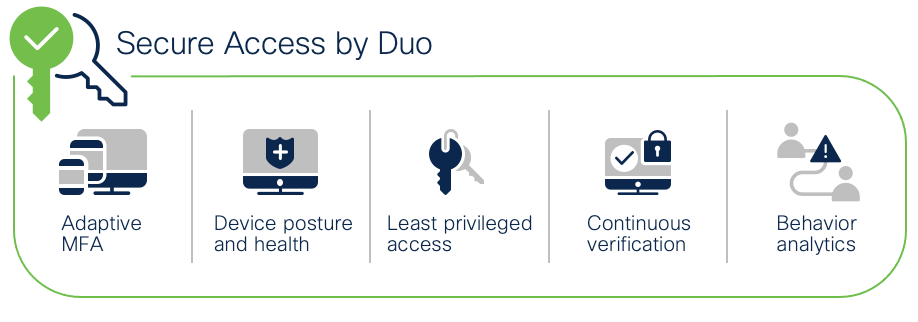
Cisco Secure Access by Duo
Zero trust can be summed up as “never trust; always verify.” This security approach treats every access attempt as if it originates from an untrusted network — so access won’t be allowed until trust is demonstrated. Once users and devices have been deemed trustworthy, zero trust ensures that they have access only to the resources they absolutely need, to prevent any unauthorized lateral movement through an environment. Highlights of Cisco Secure Access by Duo include:
● MFA – Enforce secure identity verification methods, like Duo Push
● User Access Policies – Options to set policies for specific user groups either globally or by application
● Cloud Based Single Sign-On (SSO) – Enable SSO for any SAML2-enabled app, to consolidate users’ login workflows under a single set of credentials protected by strong MFA
● Duo Device Health – Monitor laptop and desktop devices to ensure they have the right security protocols in place
● Secure Endpoint integration – When Duo and Cisco Secure Endpoint have shared visibility into a Windows or macOS endpoint, user access can be blocked to applications protected by Duo from endpoints deemed compromised by Cisco Secure Endpoint
Cisco Secure Endpoint with Secure Malware Analytics
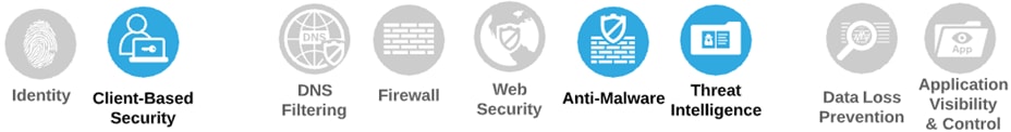
SAFE Capability – Client-Based Security & Network Anti-Malware
Cisco Secure Endpoint offers cloud-delivered endpoint protection and advanced endpoint detection and response across multi-domain control points. Capabilities include:
● Prevention – Block known malware automatically leveraging the best global threat intelligence and enforce Zero Trust by blocking risky endpoints from gaining access to applications
● Detection – Run complex queries and advanced investigations across all endpoints, and continuously monitor all file activity to detect stealthy malware
● Response – Rapidly contain the attack by isolating an infected endpoint and remediating malware across PCs, Macs, Linux, servers, and mobile devices (Android and iOS)
For files that have unknown disposition to Cisco Secure Endpoint, Secure Malware Analytics (formerly Threat Grid) combines advanced sandboxing with threat intelligence into one unified solution to protect organizations from malware. With a robust, context-rich malware knowledge base, you will understand what malware is doing, or attempting to do, how large a threat it poses, and how to defend against it.
Cisco Secure Malware Analytics is out of scope for this guide. For more information, see the Cisco Breach Defense Design Guide.
Seamless integration between Umbrella and Viptela
While both products have their own separate management clouds, the integration between Umbrella (security as a service) and Cisco SD-WAN (networking as a service) is done in minutes to instantly gain protection against threats like malware, ransomware, and C2 callbacks. You gain the cost-savings and improved performance of DIA at branch offices, without sacrificing security or the burden of managing devices individually.
With this integration, tunnels are automatically created from SD-WAN routers to the Umbrella cloud, enabling administrators to create routing policies for DIA while managing security centrally for all Internet bound traffic across the full SD-WAN network.
Cisco has been on a mission for several years to simplify security. That mission culminated in the launch of the Cisco SecureX platform, which integrates the entire Cisco security portfolio as well as additional security, networking, and IT technologies from both Cisco and third parties. It is included with all the Cisco security products, so once you have one, you can begin using SecureX.
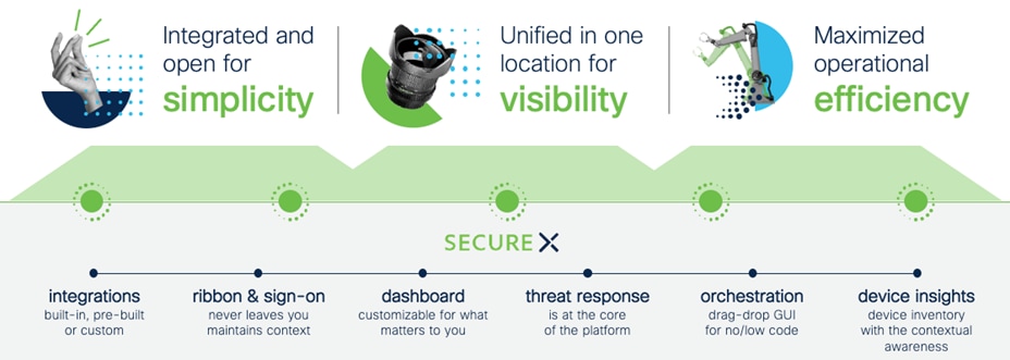
Cisco SecureX
Cisco SecureX brings together key security technologies considered fundamental for SASE with unified visibility and control through one console. Highlights include:
● Unified visibility – Experience simplicity with a customizable dashboard that included operational metrics, visibility into emerging threats, and access to new products in a single click
● Threat Response – Accelerate threat investigations and incident management by aggregating and correlating global intelligence and local context in one view
● Orchestration – Automate routine tasks using prebuilt workflows that align to common use cases, or build your own workflows with a no-to-low code, drag-and-drop canvas
● Ribbon and single sign-on – Use the dashboard ribbon for quick access to Cisco SecureX features. SSO helps share and maintain context around incidents in one location
● SSO across all Cisco platforms – Easily access all your Cisco Security products, with one set of credentials, from any device.
With the increased reliance on the internet and cloud services, more networks are outside your ownership or direct control. Organizations need to ensure the performance and integrity of the underlying transport, even when you don’t own the infrastructure or control how service providers route traffic.
Cisco ThousandEyes
Cisco ThousandEyes is a network intelligence SaaS platform that allows users to run a variety of tests using global vantage points to monitor DNS resolution, browser response characteristics, detailed aspects of network pathing and connectivity, the status of network routing, and VoIP streaming connection quality. Highlights include:
● Reduce Mean Time to Identify and resolve by immediately pinpointing the source of issues across internal network, ISPs, and cloud and application providers
● Gain successful escalations with service providers based on data that can be easily shared across internal and external stakeholders
● Eliminate wasteful finger pointing and effectively manage OLAs/SLAs across internal teams and external providers
Cisco ThousandEyes Enterprise agents can be deployed natively as a container application on supported Cisco IOS XE SD-WAN devices to integrate Cisco SD-WAN with Cisco ThousandEyes. The enterprise agent can be installed and activated through vManage.
Viptela SD-WAN Introduction
This design guide consists of an ISR4461 pair in the branch site and an ASR1002-X in the data center. The hardware installation for these appliances can be found in the following guides:
● Hardware Installation Guide for Cisco 4000 Series Integrated Services Routers
● Cisco ASR 1000 Series Router Hardware Installation Guide
For a full list of devices that are compatible with Cisco SD-WAN, see Cisco SD-WAN Device Compatibility.
There are multiple, flexible controller deployment options available for customers. Controllers can be deployed in a:
● Cisco-hosted cloud (recommended): Most customers opt for Cisco cloud-hosted controllers due to ease of deployment and flexibility in scaling. Cisco takes care of provisioning the controllers with certificates and meeting requirements for scale and redundancy. Cisco is responsible for backups/snapshots and disaster recovery. The customer is given access to vManage to create configuration templates and policies for their devices.
● Managed Service Provider (MSP) or partner-hosted cloud: The MSP or partner is typically responsible for provisioning the controllers and responsible for backups and disaster recovery.
● On-prem data center: The customer is responsible for provisioning the controllers and responsible for backups and disaster recovery.
For this design guide, controllers were installed in an on-prem data center that is connected to both the data center and branch over a WAN interface to mimic the scenario for cloud hosted controllers. For more information on Cisco’s cloud-hosting subscription for Cisco SD-WAN controllers, see Cisco SD-WAN CloudOps.
Note: If you plan on using Cisco CloudOps, skip to the section titled ‘Onboard Router into SD-WAN Fabric’ as the immediate next steps will detail the deployment of the SD-WAN controllers.
SD-WAN Controller Setup (On-Prem)
This configuration example covers the process of installing the SD-WAN controller software images on a VMWare ESXI instance, establishing the transport and management networks for the three controllers to communicate, and ensuring that each controller has a valid certificate installed. This guide should be used in conjunction with the Cisco SD-WAN Design Guide, which provides an overview of the Cisco SD-WAN solution, including control plane, data plane, routing, authentication, and discusses many WAN edge deployment considerations and common scenarios.
Step 1. Download the OVA image for vManage, vBond and vSmart.
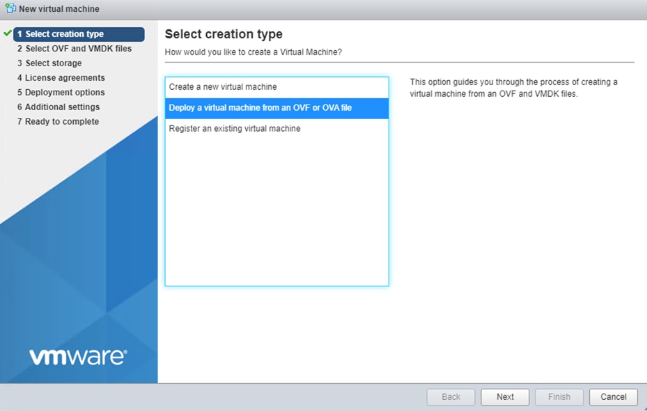
Step 2. In the ESXI management dashboard, navigate to Virtual Machines and click Create/Register VM.
Step 3. Click Deploy a virtual machine from an OVF or an OVA file.
Step 4. Starting with vManage, enter a name for the virtual instance and select the downloaded file for vManage.
Step 5. Select the datastore where the VM is going to be stored.
Step 6. Select the VM Network for the controller network and select Thick Provisioning for Data provisioning. Uncheck Power on automatically.
Step 7. Click Finish.
Step 8. In ESXI, navigate to Networking and click Add port group.
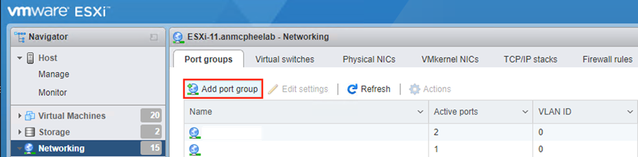
Step 9. In the pop-up window, give a meaningful Name and click Add.
Step 10. Navigate to Virtual Machines, right-click vManage and click Edit Settings.
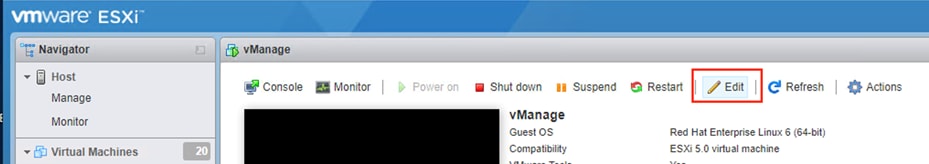
Step 11. Click Add Network Adapter and select the defined SD-WAN network for Network Adapter 2.
Step 12. Click Add Hard Disk and select New Standard Hard Disk.
Step 13. Update Hard disk 2 to 100GB so vManage has sufficient space to store all controller logs.
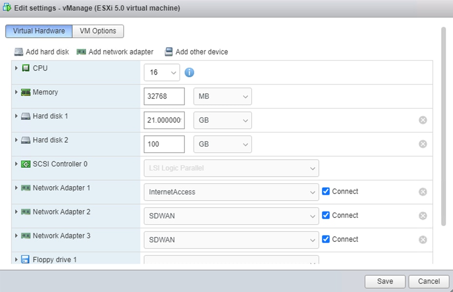
Step 14. Click Save.
Step 15. Repeat steps 2-7 for vSmart and vBond, ensuring that the first network adapter is the VM management network, and the second network adapter is the SD-WAN network.
Note: For this design guide, the controllers were managed over the WAN interface, resulting in Network Adapter 1 being the WAN interface.
Configure Controller IP Addresses
Step 1. Start all three VM instances for vManage, vBond, and vSmart.
Step 2. Log in to each VM instance using the default username/password (admin/admin).
Step 3. Using the configure terminal command, configure the system with the following:
vManage
system
host-name vManage
system-ip 1.1.1.1
organization-name sasecvd
sp-organization-name sasecvd
site-id 1
vbond <VBOND_PUBLIC_IP>
commit
end
vSmart
system
host-name vSmart
system-ip 1.1.1.2
organization-name sasecvd
sp-organization-name sasecvd
site-id 1
vbond <VBOND_PUBLIC_IP>
commit
end
vBond
system
host-name vBond
system-ip 1.1.1.3
organization-name sasecvd
sp-organization-name sasecvd
site-id 1
vbond <VBOND_PUBLIC_IP> local vbond
commit
end
Step 4. Once the controllers are setup, configure the transport VPN using the following commands:
vManage & vSmart
vpn 0
interface eth0
ip address <PUBLIC_IP>
no shut
tunnel-interface
allow-service all
commit
exit
exit
ip route 0.0.0.0/0 <PUBLIC_IP_GATEWAY>
commit
end
vBond
vpn 0
interface ge0/0
ip address <PUBLIC_IP>
no shut
tunnel-interface
encapsulation ipsec
allow-service all
commit
exit
exit
ip route 0.0.0.0/0 <PUBLIC_IP_GATEWAY>
commit
end
Configure Controller Certificates
Controller identity is provided by a Symantec/Digicert or Cisco-signed certificate, or alternatively, an Enterprise CA certificate. Each controller in the network must have a certificate signed and installed. In addition, the root certificate chain for the corresponding CA must also be installed on each controller before the controller certificates can be installed.
For this design guide, an Enterprise CA is used to provide controller certificate authorization. For more technical guidance on the steps needed to successfully install controller certificates, see Cisco SD-WAN Controller Certificates and Authorized Serial Number File Prescriptive Deployment Guide.
Step 1. Login to the vManage dashboard by navigating to https://<VMANAGE_PUBLIC_IP>:8443 in a web browser.
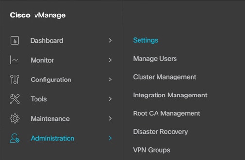
Step 2. Navigate to Administration > Settings.
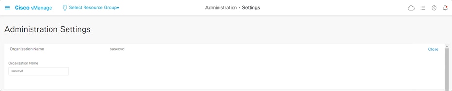
Step 3. Configure the Organization Name to match the one configured on each controller during setup.
Step 4. Enter the vBond IP address with the default port 12346 unless an alternate was configured.
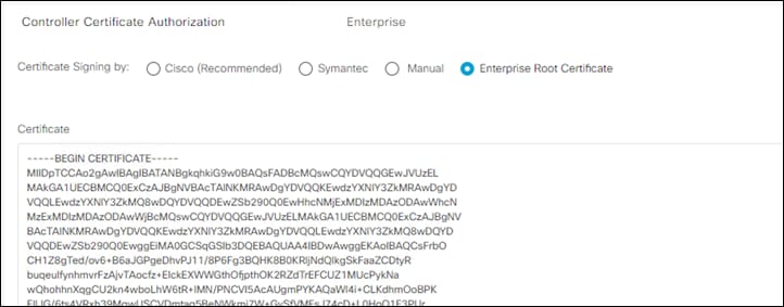
Step 5. Edit the Controller Certificate Authorization and click Enterprise to use a custom Root CA for signing controller certificates.
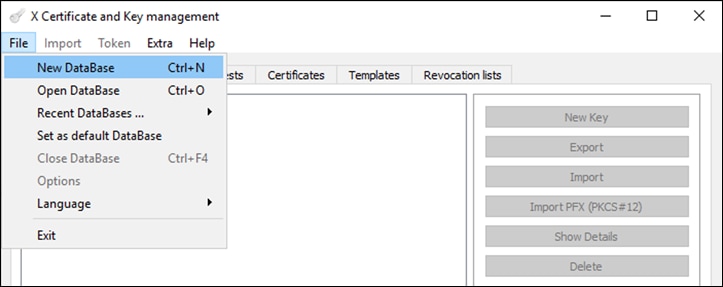
Note: There are many options for creating and signing certificates, and each will work with the SD-WAN controllers, however, this guide will cover how to do so using the XCA certificate-signing software as it is available for free.
Step 6. In XCA, select File > New Database and specify a name to create a new .xdb database. Click Save.
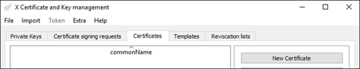
Step 7. In the Certificates tab, click New Certificate.
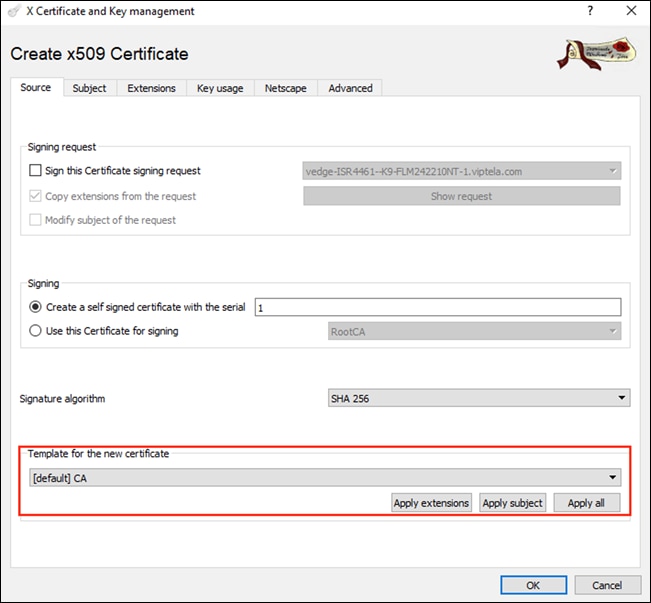
Step 8. In the Source tab, in the Template for the new certificate field, select [default] CA. Click Apply extensions, Apply subject, and Apply all.
Step 9. In the Subject tab, enter the name RootCA in the field for Internal Name. Fill out the remaining details in correspondence with your organization.
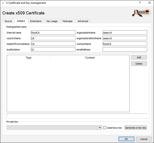
Note: The organizationName and organizationalUnitName fields must be identical and should match the organization name configured previously in each of the controllers, as well as the vManage dashboard.
Step 10. Click Generate a new key. Click Create and OK.
Step 11. After the certificate has been created, select it, and click Export to save the certificate in PEM (.crt) format.
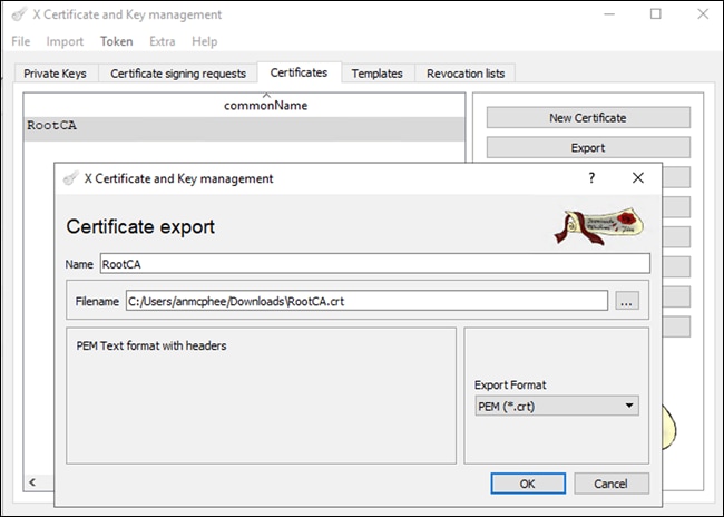
Step 12. Using a text editor, or terminal window, open the file and copy all the certificate text, including the Begin Certificate and End Certificate line.
Step 13. In the vManage console, paste the contents of the root certificate into the setting for Controller Certificate Authorization. Click Import & Save.
Step 14. SSH into vManage using the same IP address and credentials used to login to the vManage dashboard.
Step 15. Enter the command vshell to enter the virtual shell on vManage.

Step 16. Enter the command cd /home/admin to navigate to the admin directory.

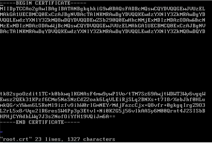
Step 17. Enter the command vim root.crt to enter the VIM text editor and create a new blank file titled root.crt.
Step 18. Enter the command i to enter insert mode in VIM and paste the contents of the RootCA certificate (right clicking the console will copy the contents from the clipboard).
Step 19. Press esc to exit insert mode in VIM and enter the command to :wq to save the file and close the VIM editor.
Step 20. Enter the command exit to exit the virtual shell.
Step 21. Enter the command request root-cert-chain install /home/admin/root.crt to install the root certificate chain.

Step 22. Repeat steps 14-21 for establishing an SSH session with vSmart and vBond to install the root certificate on each controller.
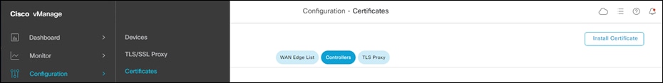
Step 23. In the vManage dashboard, navigate to Configuration > Certificates and select Controllers.
Step 24. Click the three dots at the right of the vManage line to open the options menu for the vManage certificate. Click Generate CSR to generate a certificate signing request for vManage.
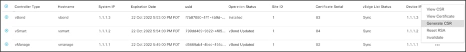
Step 25. Click Download. Rename the CSR file to match the name of the controller (i.e., vManage.csr)
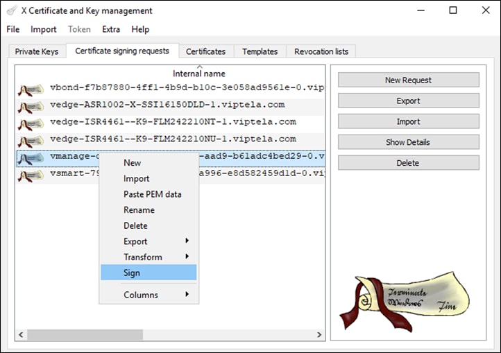
Step 26. In XCA, navigate to the Certificate Signing Requests tab and click Import to import the CSR that was downloaded from the vManage dashboard.
Step 27. Once imported, right click the name of the CSR and click Sign.
Step 28. In the Source tab, under the field Signing, ensure that the RootCA certificate that was created earlier is selected as the certificate used for signing.
Step 29. Under Template for the new certificate, select [default] HTTPS_client then click Apply extensions, Apply subject, and Apply all.
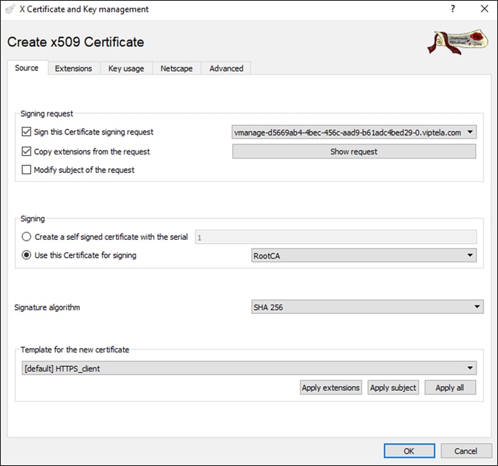
Step 30. In the Extensions tab, to ensure that the certificate becomes valid immediately once installed on the controller, the time displayed in the Not before window should be updated to be the current time on the respective controller (the time on the controller can be checked by typing the command show clock on the command line).
Step 31. Click OK to sign the certificate.
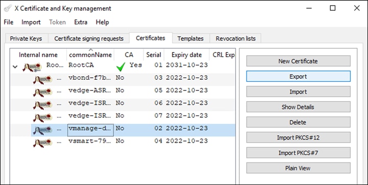
Step 32. In the Certificates tab, click the drop-down arrow to the left of the RootCA certificate generated in a previous step.
Step 33. Right click the certificate whose name corresponds to the controller for which the certificate is being signed for and select Export > Clipboard.
Step 34. In the vManage dashboard, return to the Configuration > Certificates page, click Controllers and click Install Certificate.
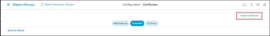
Step 35. Paste the contents of the signed certificate and click Install.
Step 36. After the certificate installation has finished, there will be a message indicating it was successful.
Step 37. Navigate to Configuration > Devices and select the Controllers tab.
Step 38. Click Add Controller and select vBond.
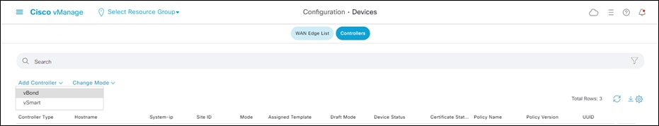
Step 39. Enter the vBond public IP address and credentials for logging on to the console.
Step 40. Ensure that the Generate CSR is NOT checked and click Add.
Step 41. Repeat steps 37-40 to add the vSmart controller.
Step 42. Repeat steps 23-36 to generate the CSRs, as well as sign and install the certificates for both vBond and vSmart.
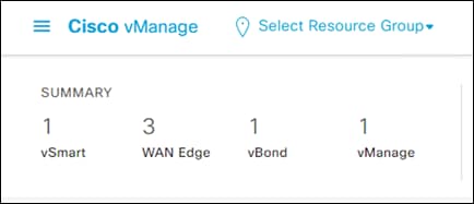
Step 43. Upon completing the controller setup and certificate installation, the vManage dashboard should indicate that each of the three controllers are up and reachable.
Onboard Router into SD-WAN Fabric
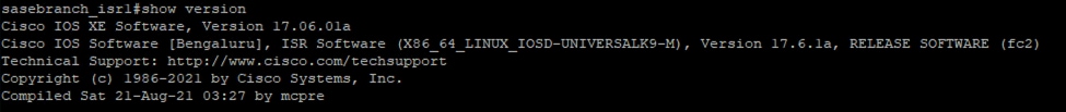
In this design guide, all routers that have been added to the fabric are running IOS-XE v17.06.01. The router’s software image version can be checked by issuing the show version command on the router’s CLI.
This design guide makes use of an ASR1002-X at the data center and the ISR4461 platform in the branch. For image upgrade instructions see:
● Cisco 4000 Series ISRs Software Configuration Guide
● Cisco ASR 1000 Series Aggregation Services Routers Software Configuration Guide
Note: If the devices are running an older version of SD-WAN compatible software, the device can be upgraded through the vManage dashboard. For more information see Manage Software Upgrade and Repository.
There are several options available to securely onboard SD-WAN edge devices.
● Plug-and-Play (PnP): A Day-zero process that provides a simple, secure procedure to discover, install and provision Cisco IOS-XE SD-WAN edge devices.
● Zero-Touch Provisioning (ZTP): A Day-zero process that provides a simple, secure procedure to discover, install and provision vEdge devices.
● Bootstrap deployment: An alternate option to deploy IOS-XE WAN edge devices. The configuration needed to securely onboard the device is loaded into the bootflash memory (or via USB) which is then used during initial bootup.
● Manual deployment: WAN edge device is given the bare minimum configuration needed to reach the vBond SD-WAN controller using the CLI.
For this design guide, a manual deployment was chosen (steps shown below). For more deployment options see WAN Edge Onboarding.
Step 1. Connect to the router’s console using an admin account.
Step 2. Enter configuration mode by entering config-t and enter the following commands to establish basic connectivity to vBond
ip route 0.0.0.0 0.0.0.0 <GATEWAY IP>
interface GigabitEthernet0/0/0
ip address <WAN IP> <SUBNET MASK>
no shut
commit
end
Step 3. Ping the vBond IP address to test connectivity can be achieved.
Step 4. Once the route is verified, enter the configuration mode again (config-t) and enter the following command to establish control connections with the SD-WAN controllers.
hostname sasebranch_isr1
system
system-ip 3.1.1.1
site-id 3
organization-name sasecvd
vbond <VBOND PUBLIC IP>
exit
interface Tunnel 0
ip unnumbered GigabitEthernet0/0/0
tunnel source GigabitEthernet0/0/0
tunnel mode sdwan
interface GigabitEthernet0/0/0
tunnel-interface
color default
encapsulation ipsec
commit
end
Step 5. Copy the Root Certificate file that was added to vManage for Controller authentication into the routers bootflash. For an example see Appendix C.
Step 6. Once the file has transferred, issue the following command
request platform software sdwan root-cert-chain install bootflash:<ROOT CERT FILENAME>
Note: For the edge router to appear in the devices list on vManage, a valid WAN edge device list will need to be signed and uploaded to vManage. On vManage 17.x and newer, the WAN edge serial file is a signed, binary file that can only be obtained through Cisco. These WAN edge serial files can be downloaded from the Network Plug and Play Connect portal, using a valid Cisco Smart Account. For information on connecting both the WAN edge devices and the vBond SD-WAN controller to the PnP Connect portal, see Appendix C in the Cisco SD-WAN Deployment Guide.
Step 7. In vManage, navigate to Configuration > Devices.
Step 8. Click Sync Smart Account.
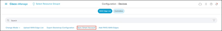
Step 9. Enter the Username and Password for the smart account in which the WAN edge devices and appropriate vBond controller profile exist and click Sync to load the device list into vManage.
Note: For most platforms, such as vEdge or the ISR 4000 series IOS-XE devices, no further configuration is needed to authenticate to the network. However, this design guide consists of the ASR1002-X platform which does not contain a SUDI certificate for automatic authentication by the controller network. To authenticate the ASR device, the user has the option of generating a bootstrap configuration which contains a one-time password to use at bootup, or, as this design guide will show, make use of an Enterprise CA.
Note: The following steps are only required if using Enterprise CA for Hardware WAN Edge Certificate Authorization.
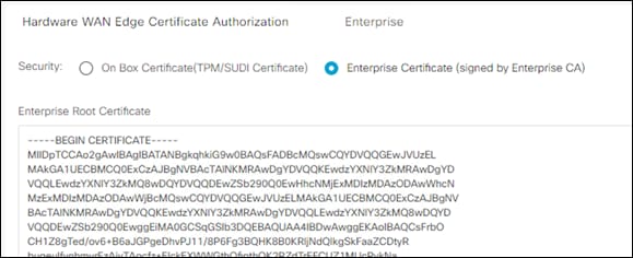
Step 1. In vManage, navigate to Administration > Settings.
Step 2. Next to Hardware WAN Edge Certificate Authorization click Edit.
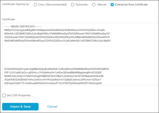
Step 3. Click Enterprise Certificate and paste the RootCA used to sign the Controller Certificates in the previous section.
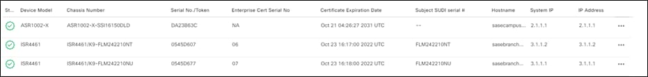
Step 4. Navigate to Configuration > Certificates.
Step 5. Click the three dots at the right of the WAN edge device and click Generate Device CSR.
Step 6. Download the CSR. Make sure the name matched the edge device.
Step 7. In XCA, navigate to the Certificate Signing Requests tab and click Import to import the CSR that was downloaded from the vManage dashboard.
Step 8. Once imported, right click the name of the CSR and click Sign.
Step 9. In the Source tab, under the field Signing, ensure that the RootCA certificate that was created earlier is selected as the certificate used for signing.
Step 10. Under Template for the new certificate, select [default] HTTPS_client then click Apply extensions, Apply subject, and Apply all.
Step 11. In the Extensions tab, to ensure that the certificate becomes valid immediately once installed on the controller, the time displayed in the Not before window should be updated to be the current time on the respective controller (the time on the controller can be checked by typing the command show clock on the command line).
Step 12. Click OK to sign the certificate.
Step 13. In the Certificates tab, click the drop-down arrow to the left of the RootCA certificate generated in a previous step.
Step 14. Right click the certificate whose name corresponds to the controller for which the certificate is being signed for and select Export > Clipboard.
Step 15. In the vManage dashboard, return to the Configuration > Certificates page and click Install Certificate.
Step 16. Paste the contents of the signed certificate and click Install.
Step 17. After the certificate installation has finished, there will be a message indicating it was successful.
Step 18. Repeat for all WAN edge devices.
Verify Control Connections
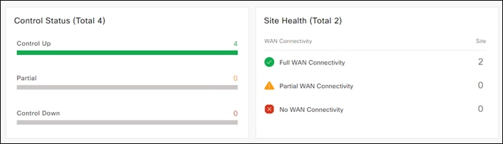
Step 1. In the vManage dashboard, navigate to Dashboard > Main Dashboard.
Step 2. Check for information on overall fabric health such as Control Status and Site Health indicators.
Configuring Devices using vManage Templates
Device templates define a device’s complete operational configuration. A device template consists of several feature templates. Each feature template defines the configuration for a particular Viptela software feature. Some feature templates are mandatory, indicated with an asterisk (*), and some are optional. Each mandatory feature template, and some of the optional ones too, have a factory-default template. For software features that have a factory-default template, you can use either the factory-default template or you can create a custom feature template.
For this design guide, two device templates are created. One device template is used to configure the ISR 4461 pair at the branch and will be configured to connect to both the default color tunnel for controller connectivity and Data Center network access, and a SIG breakout tunnel for internet connectivity. The second device template will be configured to only connect to the default tunnel, where its connected subnets are advertised to connected sites.
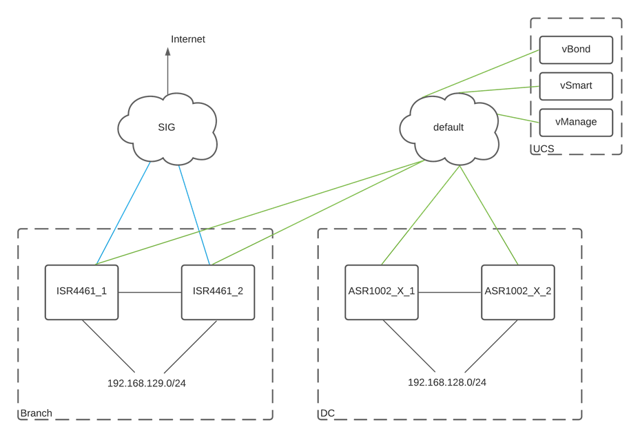
Cisco SD-WAN deployment
Configuration Template for vSmart Controller
After the Cisco vBond Orchestrator authenticates WAN edge devices, vBond provides the WAN edge devices information to connect to vSmart. A Cisco vSmart Controller controls the flow of data traffic throughout the network via data and application-route policies. For the vSmart controller to function, it must be configured by a vManage device template.
The following configuration steps is a represents the same configuration that has already been applied to the vSmart during initialization. Replace the below with the configuration applied to your vSmart.
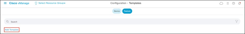
Step 1. In the vManage dashboard, navigate to Configuration > Templates and click Feature to navigate to feature templates.
Step 2. Click Add Template.
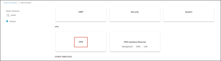
Step 3. Click vSmart > VPN.
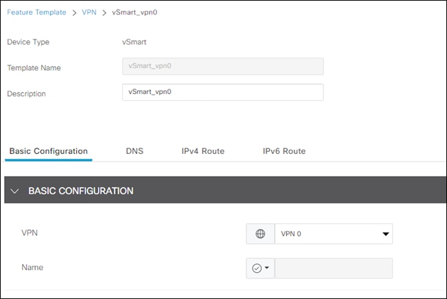
Step 4. Give a meaningful Template Name and Description.
Step 5. Under Basic Configuration, choose VPN 0.
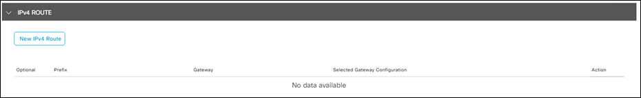
Step 6. Under IPv4 Route, click New IPv4 Route.
Step 7. Add 0.0.0.0/0 to the Prefix and Add Next Hop gateway.
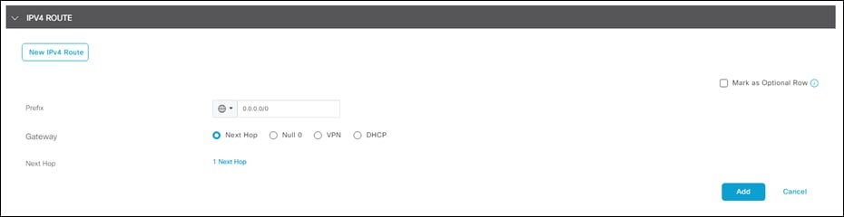
Step 8. Click Save.
Step 9. Back in the Feature templates section, click Add Template.
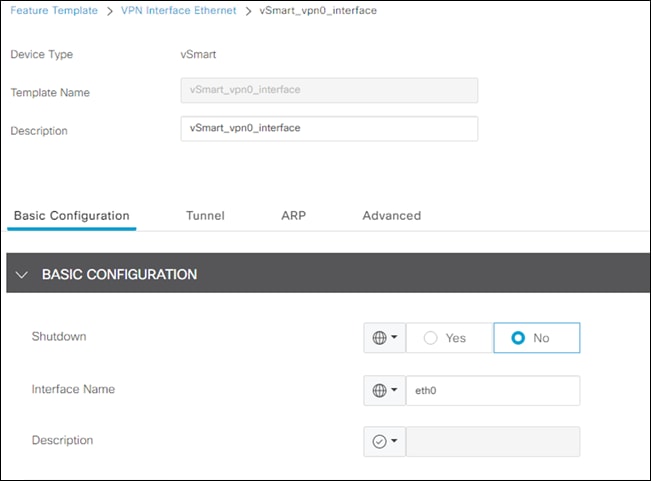
Step 10. Click vSmart > VPN Interface Ethernet.
Step 11. Give a meaningful Template Name and Description.
Step 12. Under Basic Configuration, click No Shutdown and the Interface Name for VPN 0 is eth0.
Step 13. Under IP Configuration click Static and enter the IPv4 Address of the vSmart Controller.
Step 14. Under Tunnel, click On next to Tunnel Interface and leave Color as default.
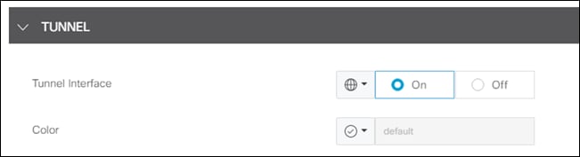
Step 15. Click Save.
Step 16. Navigate to Configuration > Templates and stay on the Device tab.
Step 17. Click Create Template > From Feature Template.
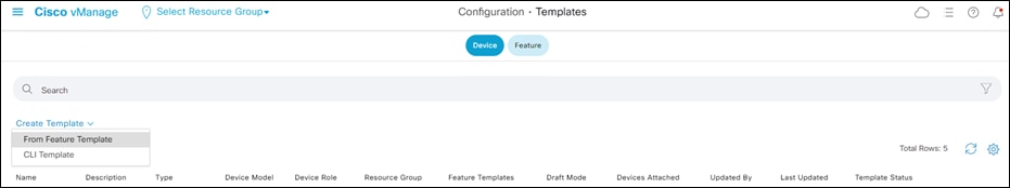
Step 18. Under Device Model choose vSmart.
Step 19. Give a meaningful Template Name and Description.
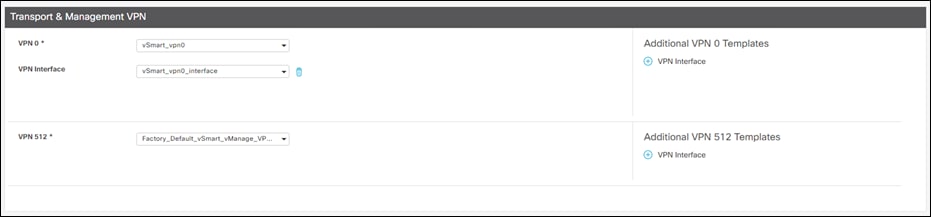
Step 20. Under Transport & Management VPN, choose the newly created template for VPN 0.
Step 21. Under Additional VPN 0 Templates, click + VPN Interface.
Step 22. Add the newly created template for the VPN 0 Interface.
Step 23. Click Create.
Step 24. Once created, click the three dots at the right of the vSmart device template and click Attach Devices.
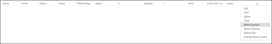
Step 25. Choose the vSmart Controller and click Attach.
Step 26. Enter the necessary variables and click Next.
Step 27. Click Configure Devices.
Step 28. After the configuration has finished, there will be a message indicating it was successful.
Basic Configuration Templates
Devices in the overlay network that are managed by Cisco vManage must be configured from Cisco vManage. Since the basic configuration procedure mimics what has already been shown for vSmart (Create feature templates > Create Device templates > Attach Device templates to individual devices), the step-by-step instructions will not be shown. Instead, the feature templates will be shown in the following tables.
Note: Variables marked with [] are device specific variables and must be specified when being attached to the device. All other variables have been defined as global variables in the template.
| ASR1002-X > Cisco VPN |
||
| Template Name |
asr_vpn0 |
|
| Description |
VPN 0 template for ASR1002-X |
|
| Basic Configuration |
||
|
|
VPN |
0 |
| DNS |
||
|
|
Primary DNS Address (IPv4) |
192.168.128.3 |
|
|
Secondary DNS Address (IPv4) |
208.67.222.222 |
| IPv4 Route |
||
|
|
Prefix |
0.0.0.0/0 |
|
|
Gateway |
Next Hop |
|
|
Next Hop |
<WAN GATEWAY> |
| ASR1002-X > Cisco VPN Interface Ethernet |
||
| Template Name |
asr_wan_interface |
|
| Description |
Ethernet interface template for ASR1002-X WAN port |
|
| Basic Configuration |
||
|
|
Shutdown |
No |
|
|
Interface Name |
GigabitEthernet0/0/0 |
|
|
IPv4 |
Static |
|
|
IPv4 Address/ prefix-length |
[vpn_wan_if_ipv4_address] |
| Tunnel |
||
|
|
Tunnel Interface |
On |
|
|
Color |
default |
| NAT |
||
|
|
NAT |
On |
|
|
NAT Type |
Interface |
| ASR1002-X > Cisco VPN |
|||
| Template Name |
asr_vpn1 |
||
| Description |
VPN 1 template for ASR1002-X |
||
| Basic Configuration |
|
||
|
|
VPN |
1 |
|
| Advertise OMP |
|||
|
|
Protocol |
Connected |
|
|
|
Protocol |
Static |
|
| IPv4 Route |
|||
|
|
Prefix |
0.0.0.0/0 |
|
|
|
Gateway |
VPN |
|
|
|
Enable VPN |
On |
|
| ASR1002-X > Cisco VPN Interface Ethernet |
||
| Template Name |
asr_lan_interface |
|
| Description |
Ethernet interface template for ASR1002-X LAN port |
|
| Basic Configuration |
||
|
|
Shutdown |
No |
|
|
Interface Name |
GigabitEthernet0/0/1 |
|
|
IPv4 |
Static |
|
|
IPv4 Address/ prefix-length |
[vpn_lan_if_ipv4_address] |
| VRRP |
||
|
|
Group ID |
1 |
|
|
Priority |
[vpn1_if_vrrp_priority] |
|
|
Track OMP |
On |
|
|
IP Address |
[vpn1_lan_gateway_ip] |
Note: The basic feature templates for the ISR4461 are identical to those found above. Repeat the above templates, but choose ISR4461 instead of ASR1002-X. The only change made in this design guide is the Data Center was configured to advertise static routes. Only the connected subnets are advertised in the branch network.
Verify connectivity between Branch and Data Center by pinging the private subnet of the Data Center from a device in the Branch network.
Configuration Templates for SASE
Cisco Umbrella auto tunnel support on SD-WAN-enabled WAN edge routers enables redirection of SIG traffic to the nearest Umbrella Data Center. Auto tunnel is supported on IOS-XE 17.2.1 / Viptela 20.1 or later (IOS-XE 17.4.1 / Viptela 20.4.1 or later for active/active tunnel pairs).
Step 1. In vManage, navigate to Configuration > Templates > Feature > Add Template.
Step 2. Select ISR4461 > Cisco Secure Internet Gateway.
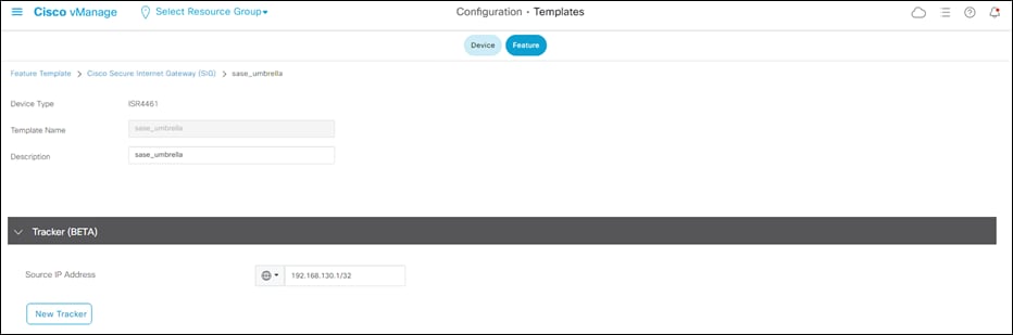
Step 3. Give a meaningful Template Name and Description.
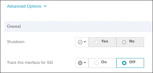
Step 4. If running a version with the Tracker (BETA) section, enter a Source IP Address. This will be disabled in a future step but is required for now.
Step 5. Under Configuration click Add Tunnel (ensure SIG Provider set to Umbrella).
Step 6. Next to Interface Name, type ipsec1 and choose the WAN interface as the Tunnel Source Interface. Click the Primary radio button next to Data Center.
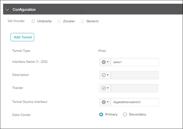
Note: If running a version of code that has the tracker enabled, click the Advanced Options dropdown menu and change Track this interface for SIG to Off. The tracker feature is out of scope for this design guide while undergoing beta tests.
Step 7. Click Add.
Step 8. Repeat steps 5-7, specifying ipsec2 and connection to the Secondary Data Center.
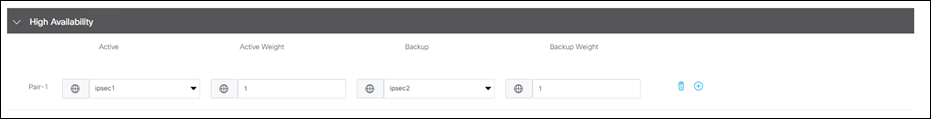
Step 9. Under High Availability, enter ipsec1 as the Active tunnel and ipsec2 as the Backup tunnel.
Step 10. Click Save.
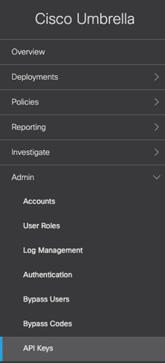
Step 11. In the Umbrella Dashboard, navigate to Admin > API Keys.
Step 12. If there is no existing key for Umbrella Management, click Create.
Step 13. Select Umbrella Management and click Create.
Step 14. Copy both the Key and Secret. Note: make sure to store the secret somewhere secure as it will only ever be shown once.
Step 15. In the vManage dashboard, navigate to Configuration > Templates > Feature > Add Template.
Step 16. Select ISR4461 > Cisco SIG Credentials.
Step 17. Enter the Organization ID along with the Registration Key and Secret for the Umbrella Management API.
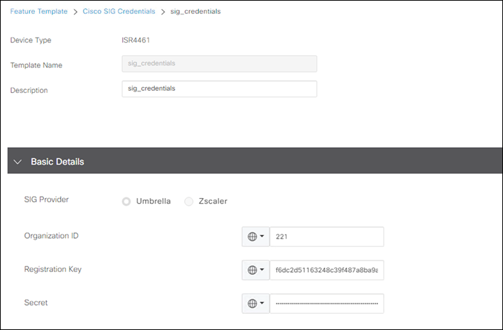
Note: To find your Organization ID from Umbrella, navigate to your Umbrella dashboard. The organization ID is part of the URL: https://dashboard.umbrella.com/o/<ORG ID>/#/
Step 18. Click Save.
Step 19. Navigate to Configuration > Templates > Device and edit the ISR4461 device template.
Step 20. Under Transport & Management VPN > Additional Cisco VPN 0 Templates click + Cisco Secure Internet Gateway.
Step 21. Add the newly attached Cisco SIG feature template.
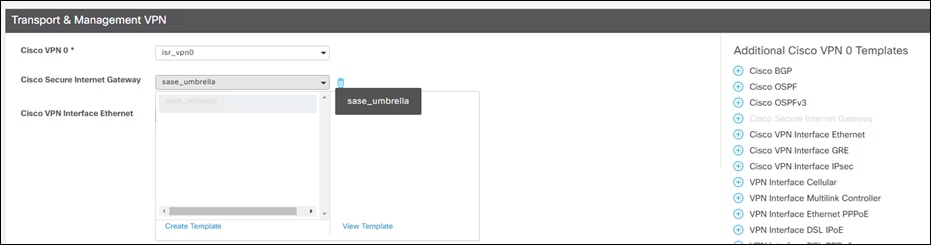
Step 22. Scroll down to Additional Templates and add the Cisco SIG Credentials feature template.
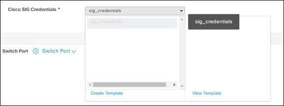
Step 23. Click Update and push changes to the devices.
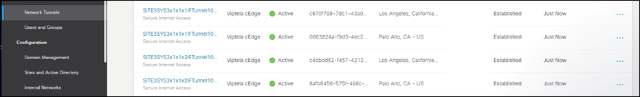
Step 24. In the Umbrella dashboard, navigate to Deployments > Core Identities > Network Tunnels.
Step 25. Check the Tunnel Status is Active between the devices.
After the tunnels are established, service routes need to be configured to forward traffic through the tunnel.
Step 1. In the vManage Dashboard, navigate to Configuration > Templates > Feature and edit the feature template for VPN 1.
Step 2. Under IPv4 Route, delete the existing VPN route for prefix 0.0.0.0/0.
Step 3. Under Service Route, click New Service Route.
Step 4. Enter the prefix 0.0.0.0/0 and click Add.
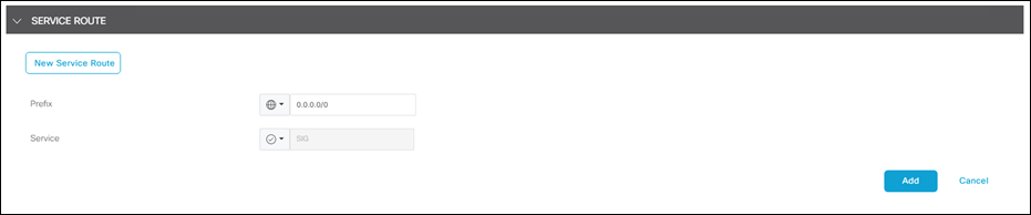
Step 5. Update the feature template and push changes to the device.
Step 6. Validate connectivity by connecting to an Internet service from a branch side computer and checking the activity log in the Umbrella Dashboard.
Note: If the tunnel to Umbrella is up, but the traffic is not being redirected through the Umbrella tunnel, try toggle the NAT configuration. During this lab setup, it was found that the NAT configuration got deleted unintentionally although the feature template was still configured for it. Deleting NAT and reconfiguring on VPN 0 re-created the NAT router required for Umbrella connectivity.
This design guide makes use of Cisco Firepower Threat Defense (FTD) devices to terminate VPN connections. Other deployment options include the use of the Cisco Adaptive Security Appliance (ASA). For configuration guidance on the ASA, see Remote VPN Client Load Balancing on ASA 5500 Configuration Example.
The Cisco AnyConnect Secure Mobility Client software package contains a profile editor for all operating systems. The only profile editor that will be configured for this guide is the AMP Enabler. For details on the other editors, including creating Always On VPN profiles for users in untrusted networks, see the Cisco AnyConnect Secure Mobility Client Administrator Guide.
Step 1. Download and install the stand-alone AnyConnect Profile Editor for Windows. Note: When using a Cisco ASA as the VPN headend, the Cisco Adaptive Security Device Manager (ASDM) activates the profile editor when you load the AnyConnect client image on the ASA. This design guide is using an FTD, which has no native support for the profile editor.
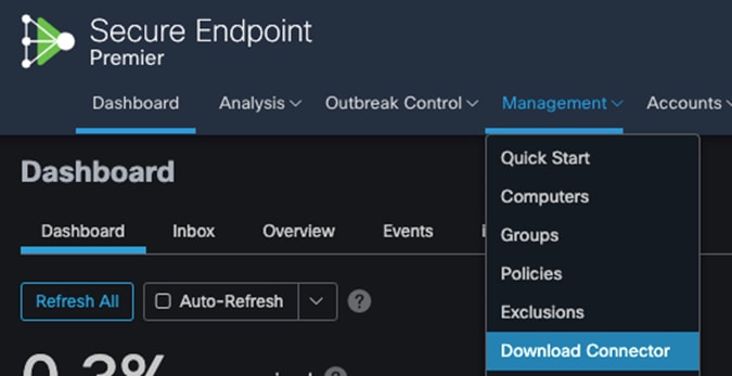
Step 2. In Secure Endpoint cloud, navigate to Management > Download Connector.
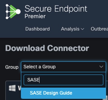
Step 3. Select the group that this policy applies. Note: If no group exists, navigate to Management > Groups and click Create Group.
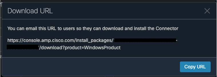
Step 4. For both Windows and Mac, click on Show URL and copy them for use in further steps.
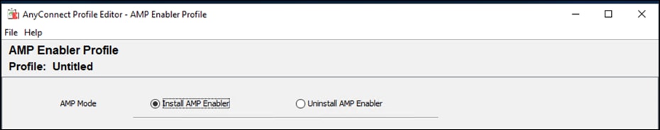
Step 5. On the windows machine that the AnyConnect profile editors have been installed, open the AnyConnect AMP Enable Standalone profile editor.
Step 6. Click Install AMP Enabler.
Step 7. Paste the URL for both Windows and Mac from step 4. Note: Make sure to remove the Https:// from the copied URLs.
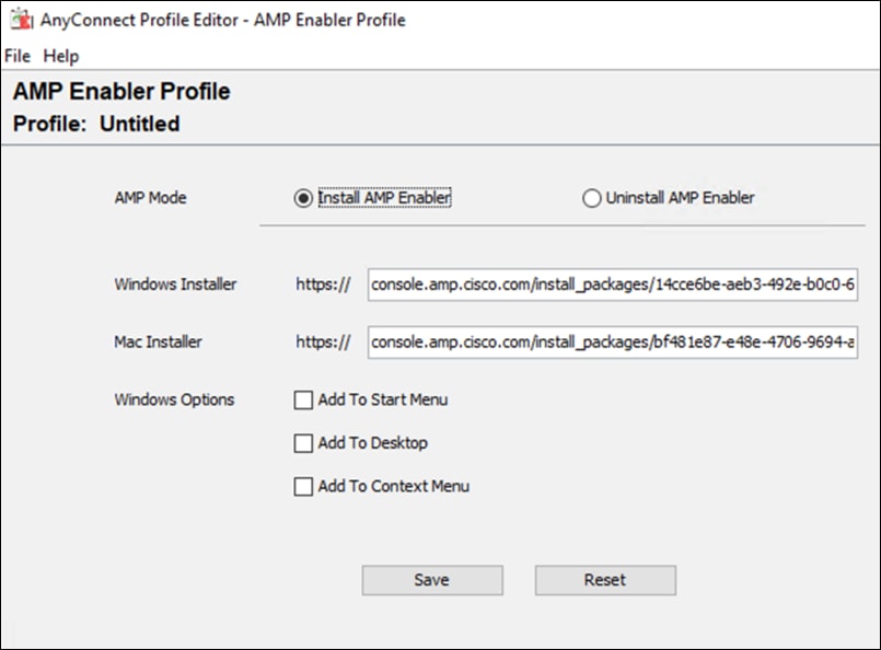
Step 8. Click Save. Note: If you press Check beside each URL and Invalid entry is returned, copy and paste the link into any browser and check if the file successfully downloads. There is an error with the tool.
The Duo Authentication Proxy is an on-premises software service that receives authentication requests from local devices and applications via RADIUS or LDAP, optionally performs primary authentication against your existing LDAP directory or RADIUS authentication server, and then contacts Duo to perform secondary authentication. The Duo Authentication Proxy is used in this guide to facilitate MFA for VPN connectivity.
The configuration of the proxy may differ depending on the application you wish to protect and the environment that it is being run in. This design guide used Cisco FTD VPN with AnyConnect – Install the Duo Authentication Proxy when installing and configuring the proxy. The proxy is installed on an Ubuntu virtual machine and primary credentials are checked against Active Directory. The configuration can be seen below.
[ad_client]
host=ad.sasecampus.com
service_account_username=administrator
service_account_password=XXXXXXXXXXXXXX
search_dn=DC=sasecampus,DC=com
[radius_server_auto]
ikey=DIXXXXXXXXXXXXXXXXXXX
skey=zSO1XXXXXXXXXXXXXXXXXXXXXXXXXXXXXXXXXXXXXX
api_host=api-aXXXXXXX.duosecurity.com
radius_ip_1=192.168.128.6
radius_secret_1=XXXXXXXXXXXXXXX
failmode=safe
client=ad_client
port=1812
Cisco Secure Firewall – Firepower Threat Defense (FTD) VPN
Cisco Firepower Management Center (FMC) provides a remote access VPN policy wizard to guide you through the required minimal steps to configure the policy. Before you start, complete the following pre-requisites to ensure the configuration elements are in place for use in the policy wizard.
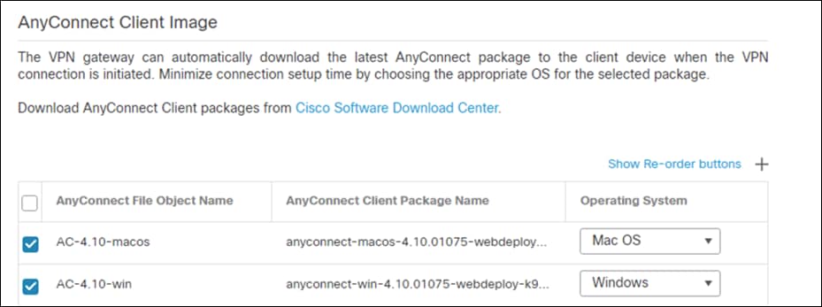
AnyConnect Client Package
Step 1. In Cisco Software Central, download the AnyConnect Headend package for Windows and Mac.
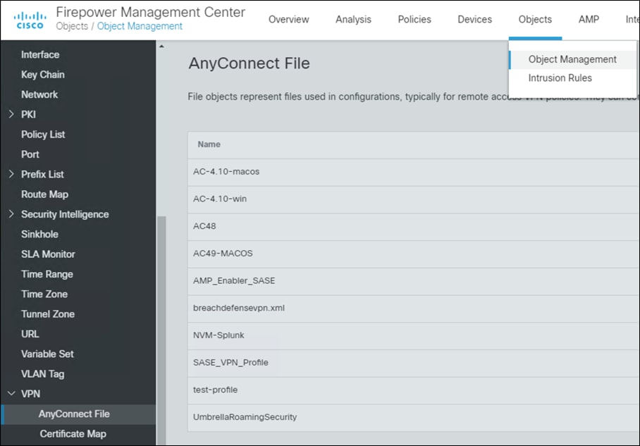
Step 2. In FMC, navigate to Objects > Object Management > VPN > AnyConnect File.
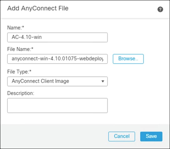
Step 3. Click Add AnyConnect File.

Step 4. Give a meaningful name to the AnyConnect File, add the headend package using the Browse button, and on the File Type dropdown menu click AnyConnect Client Image.
Step 5. Repeat for all headend packages that have been downloaded.
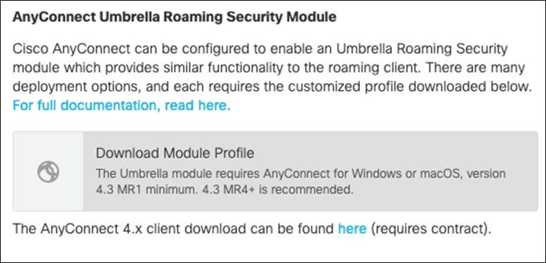
Umbrella Roaming Security Module
Step 1. In Umbrella, navigate to Deployments > Roaming Computers and click Roaming Client.
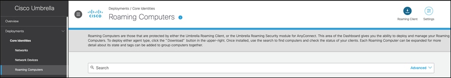
Step 2. Under AnyConnect Umbrella Roaming Security Module, click Download Module Profile.
Duo Authentication Proxy
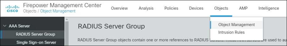
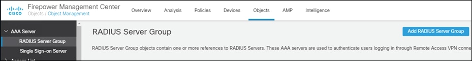
Step 1. In FMC, navigate to Objects > Object Management > AAA Server > RADIUS Server Group.
Step 2. Click Add RADIUS Server Group.
Step 3. Give a meaningful name to the server group and add the IP Address/Hostname where the Duo Authentication Proxy resides.
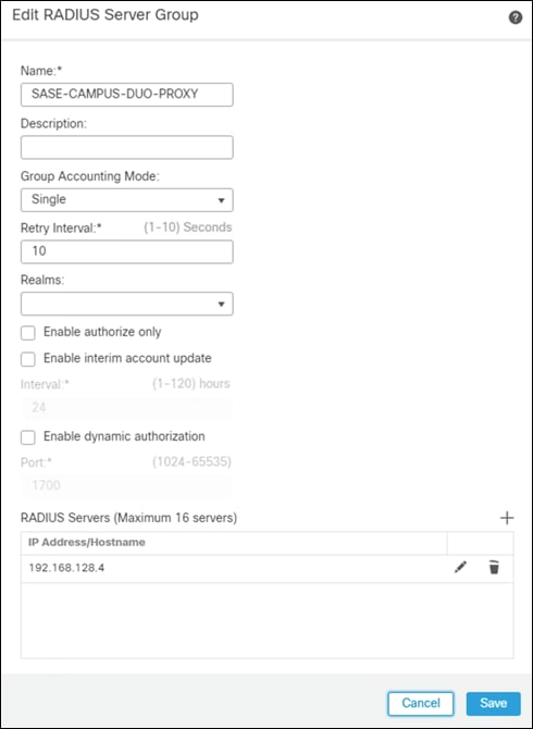
Step 4. Click Save.
VPN Address Pool
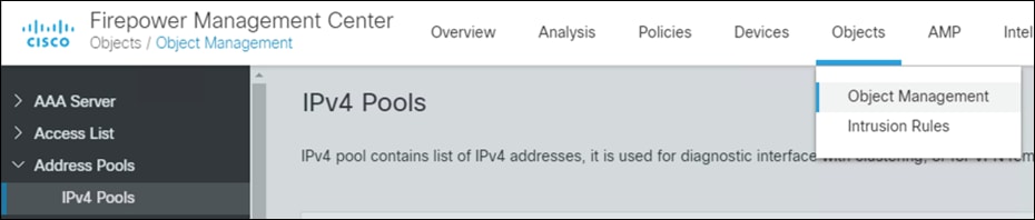
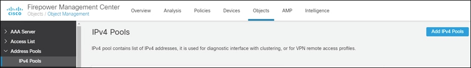
Step 1. In FMC, navigate to Objects > Object Management > Address Pools > IPv4 Pools.
Step 2. Click Add IPv4 Pools.
Step 3. Give a meaningful name to the address pool and add the IPv4 Address Range you wish to assign to VPN users.
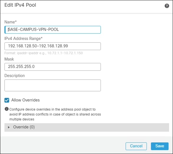
Step 4. Click Save.
VPN Split Tunnel List
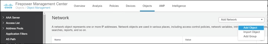
Step 1. In FMC, navigate to Objects > Object Management > Network.
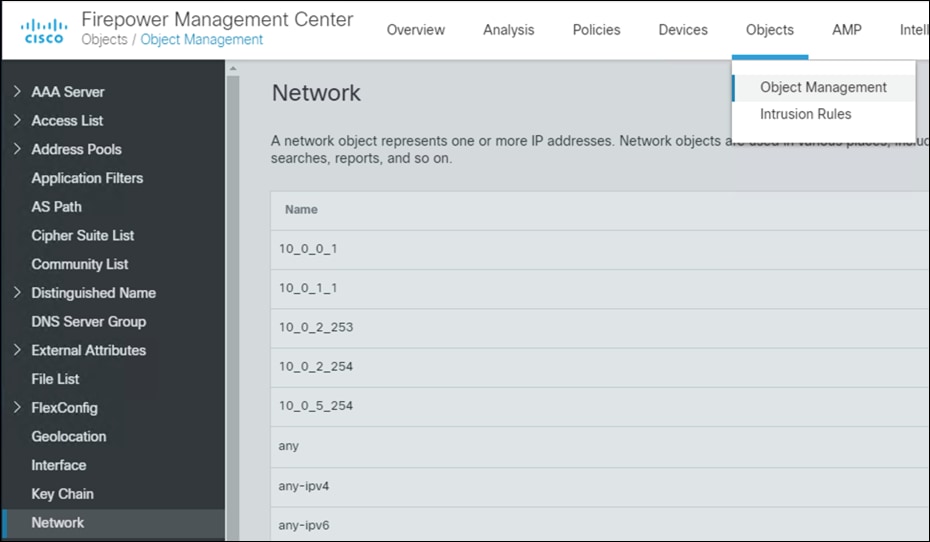
Step 2. In the Add Network drop down, click Add Object.
Step 3. Add the Network subnet that you would like roaming users to reach through the tunnel. In this design guide, roaming users will only use the VPN tunnel to access private applications, all other traffic will be sent through Umbrella.
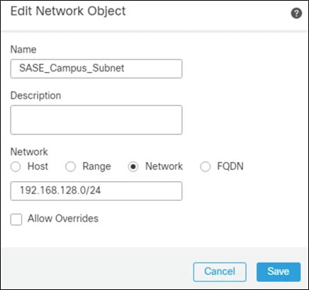
Step 4. Repeat for each subnet or host that you would like to be reachable by roaming users.
Step 5. Navigate to Objects > Object Management > Access List > Standard.
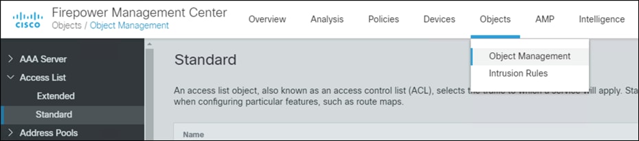
Step 6. Click Add Standard Access List.

Step 7. Give a meaningful name to the split tunnel and add the network object(s) from the previous steps.
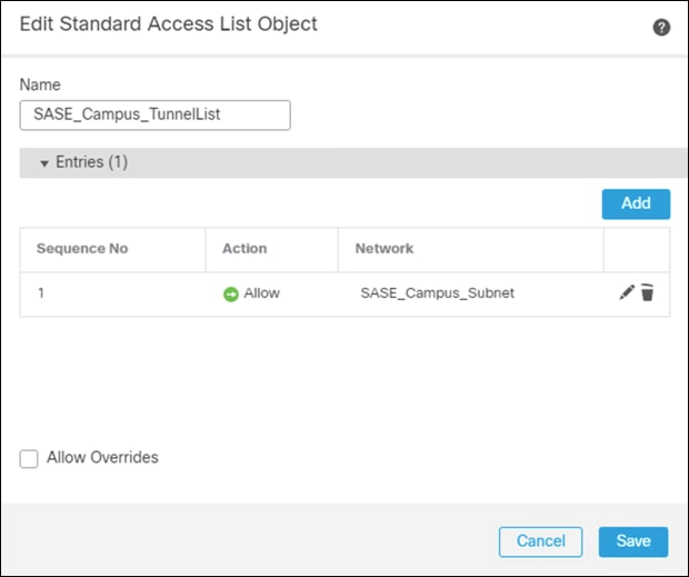
Step 8. Click Save.
Remote Access VPN Policy Wizard
The Remote Access VPN Policy wizard in the Firepower Management Center can be used to quickly and easily set up SSL and IPsec-IKEv2 remote access VPNs with basic capabilities. Then, enhance the policy configuration if desired and deploy it to your Firepower Threat Defense secure gateway devices. For this deployment guide, it is assumed that all the above pre-requisites have been completed before getting to this point.
Step 1. In FMC, navigate to Devices > VPN > Remote Access.
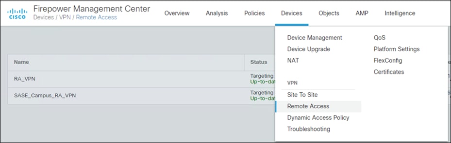
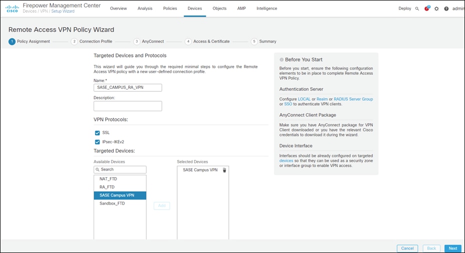
Step 2. Click Add.

Step 3. Add a meaningful name and click the FTD(s) that this policy will apply. Click Next.
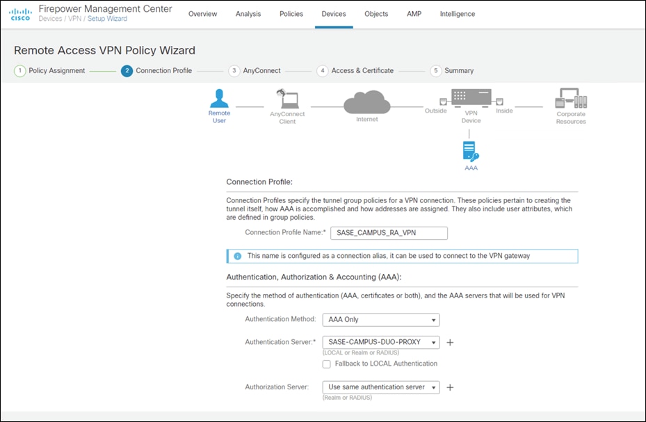
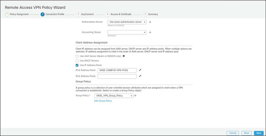
Step 4. Under Authentication Server, choose the Duo Authentication Proxy that was configured in a previous step.
Step 5. Add the IPv4 Address Pool that was created for VPN users.
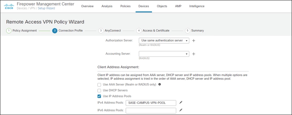
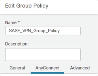
Step 6. Under Group Policy, click +.
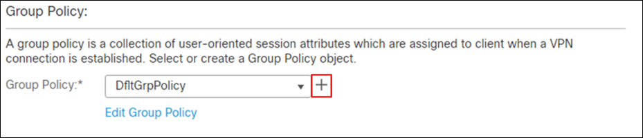
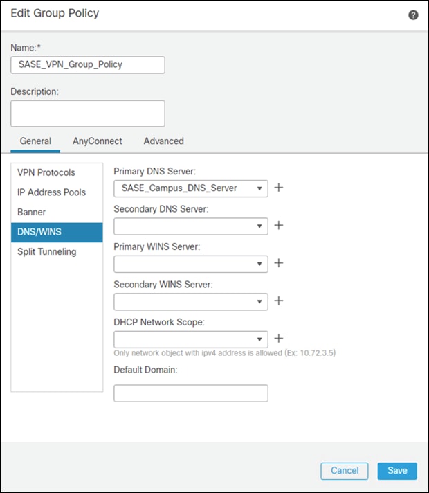
Step 7. Give a meaningful name to the policy.
Step 8. In the General > DNS/WINS tab, add the DNS server for the internal network. Note: If this network object does not already exist in FMC, it can be added using the + button.
Step 9. In the General > Split Tunneling tab, click IPv4 Split Tunneling dropdown and choose Tunnel networks specified below. Repeat for IPv6 if applicable.
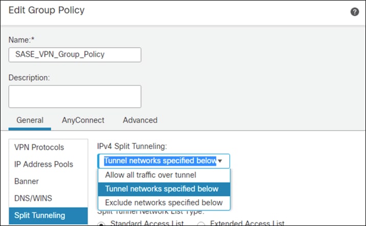
Step 10. Under Standard Access List, choose the Split Tunneling list that was created in a previous step. This will ensure that only the traffic that has been specified will use the tunnel.
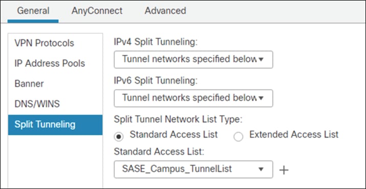
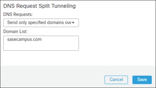
Step 11. Under DNS Request Split Tunneling, click DNS Requests dropdown and choose Send only specified domains over tunnel.
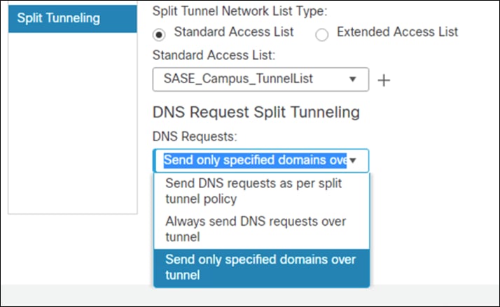
Step 12. Enter the domain list for the internal network. All other DNS requests will be sent to Umbrella (when configured).
Step 13. Navigate to the AnyConnect tab.
Step 14. In the Client Modules tab, click the + button.
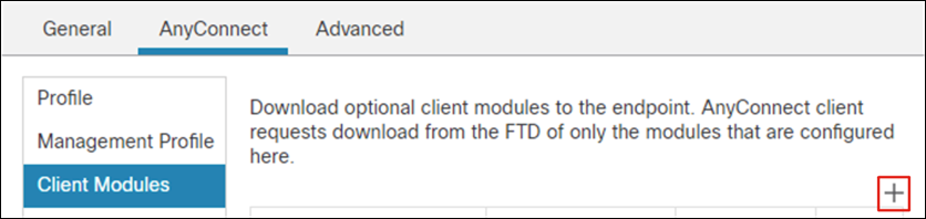
Step 15. Under Client Module, choose AMP Enabler and upload the AMP Enabler profile created in a previous step.
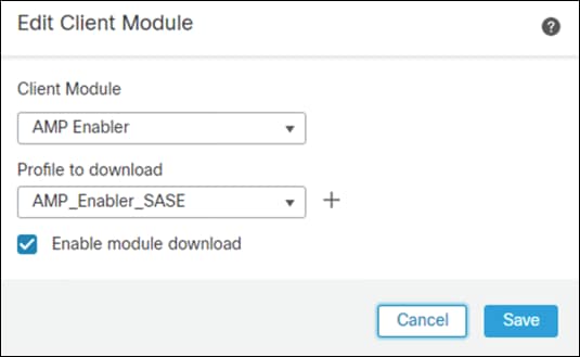
Step 16. Click Enable module download and click Add.
Step 17. In the Client Modules tab, click the + button.
Step 18. Under Client Module, choose Umbrella Roaming Security and upload the OrgInfo.json file downloaded from Umbrella in a previous step.
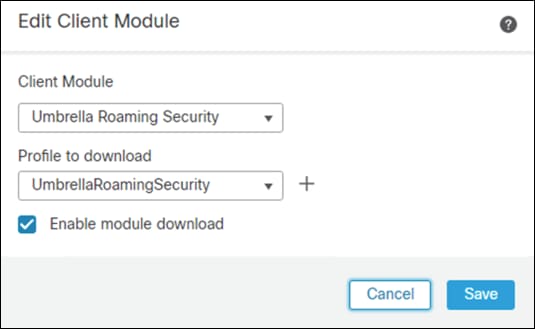
Step 19. Click Enable module download and click Add.
Step 20. Click Save on the Group Policy.
Step 21. Click Next on the Remote Access VPN wizard.
Step 22. Select the AnyConnect Client images that were uploaded in a previous step. Click Next.
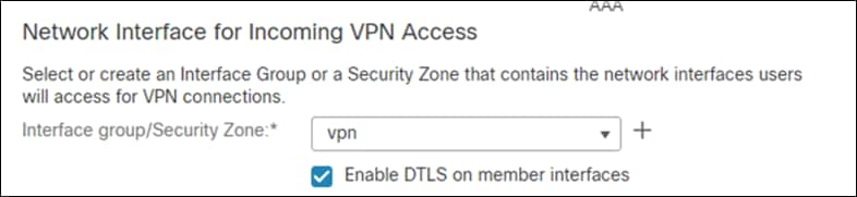
Step 23. On the Interface group/Security Zone dropdown, choose the FTD interface that users will access for VPN connections.
Step 24. In the Certificate Enrollment dropdown, choose the device certificate that will be used to authenticate the VPN gateway. Note: This design guide used a self-signed certificate that was created using the + button.
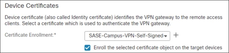
Step 25. Click Next.
Step 26. Validate the policy information and click Finish.
Step 27. Click Deploy to send remote access policy to the FTD.
Note: While out of scope for this design guide, it is recommended to create access control rules on the firewall to limit access to VPN users. This can be achieved by using the IPv4 address pool reserved for VPN users and creating an allow list of services they should be able to reach on the network.
The Duo Network Gateway allows users to access internal web applications without having to join a VPN. Users will be able to access the internal web applications after verifying their identity with a first factor and Duo MFA. For installation and configuration of the DNG see Install Duo Network Gateway.
For this design guide, DNG was installed on an Ubuntu virtual machine and the primary authenticator used was Duo SSO.
Control - Deployment
Cisco Viptela SD-WAN Security Policy
Cisco SD-WAN offers integrated security, including full-stack multilayer security capabilities on IOS XE routers. This integrated security provides real-times threat protection where and when it is needed; for branches connecting to multiple SaaS or IaaS clouds, data centers, or the Internet, further accelerating the transition to a SASE-enabled architecture.
However, this design guide has made the architectural decision to route all internet bound traffic through Umbrella, and all internal traffic will be sent back to the data center. To simplify the creation and management of security policies, all internet bound security will be performed by Umbrella, and it is assumed in this guide that the data center has the necessary security to protect its network and applications.
Note: This design guide assumes the use of Umbrella as the centralized enforcement point for the branch. Cisco IOS-XE appliances also have the capability to enforce security at the branch but its usage is out of scope for this design guide, For more information see Security Policy Design Guide for Cisco IOS-XE SD-WAN Devices.
Cisco Umbrella Security Policy
DNS Policies
Domain name system (DNS) resolution is typically the first step when connecting to a service on the Internet. Thus, enforcing security at the DNS and IP layers is the first line of defense against threats and is a great way to stop attacks before users connect to bad destinations.
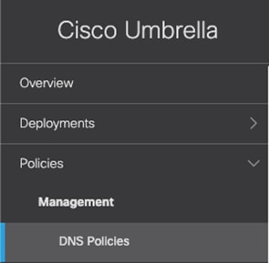
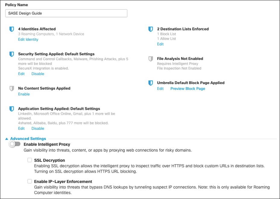
Step 1. In the Umbrella Dashboard, navigate to Policies > Management > DNS Policies.
Step 2. Click Add. Note: Your default policy in Umbrella (bottom of the list) is the catch-all for identities you haven’t defined a specific policy for. While a new policy will be created that covers all branch and roaming users, ensure that this policy is defined and enforced for all connections that have not yet been defined.

Step 3. Choose which type of access control or threats to block. For this design guide, since we have access to the full SIG suite of capabilities, we will only Block Threats in the DNS policy. Click Next.
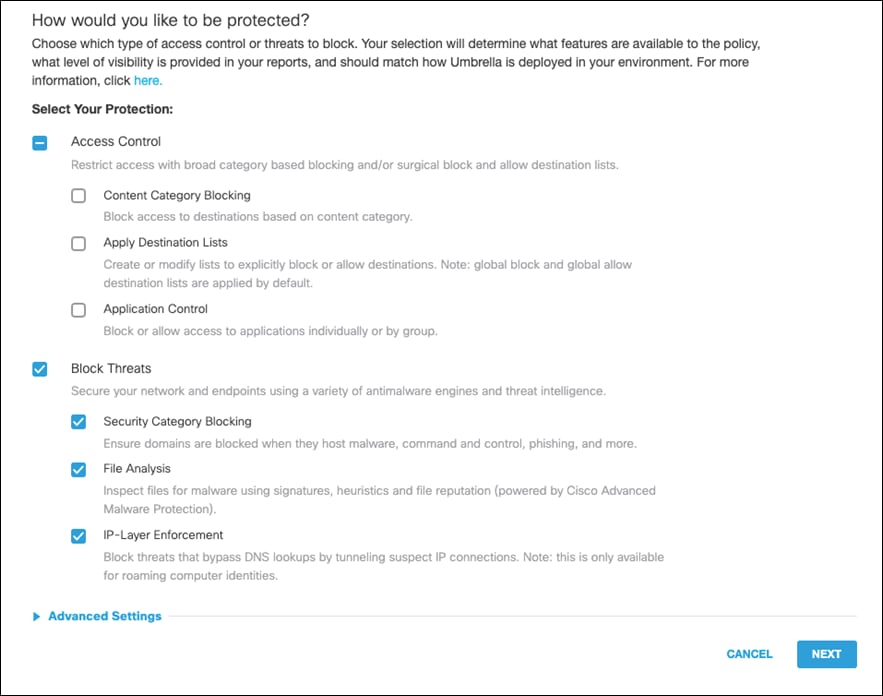
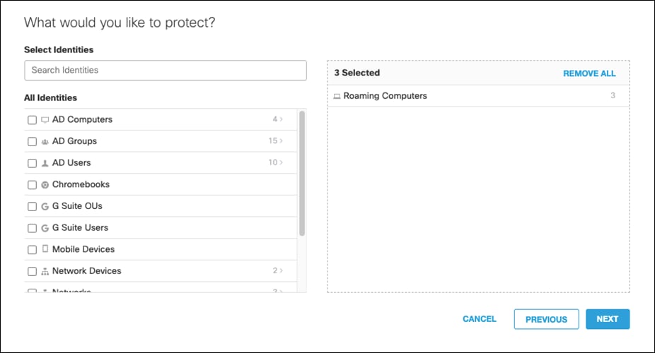
Step 4. Select the identity for Roaming Computers. This covers all identities that will be enabled through the AnyConnect Roaming Module. Branch identities will be added later after building our integration with Viptela. Click Next.
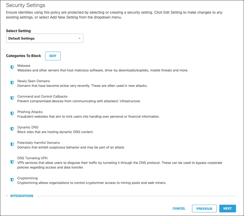
Step 5. On the Security Settings tab, leave as default and click Next.
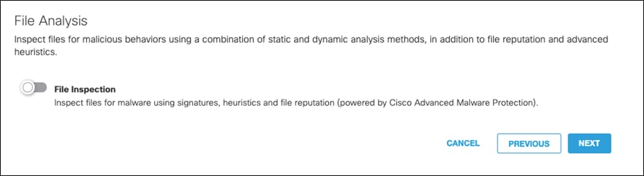
Step 6. Disable File Analysis (File inspection will occur in the web policies). Click Next.
Step 7. This design guide will leave the Block Page as default. To modify, see Customize Block and Warn Pages. Click Next.
Step 8. Give a meaningful name to the policy and review the configuration. Note: Ensure the Intelligent Proxy is disabled under Advanced Settings. If there is no option to disable, edit the policy after it has been saved and the button will appear. Click Save.
Integrate Cisco Umbrella & Cisco Viptela SD-WAN using API keys
The Cisco 4000 Series ISR acts as a DNS forwarder on the network edge, transparently intercepts DNS traffic, and forwards the DNS queries to the Cisco Umbrella cloud.
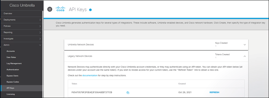
Step 1. In the Umbrella Dashboard, navigate to Admin > API Keys.
Step 2. Copy the Legacy Network Devices token (If none exists, click Create).
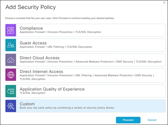
Step 3. In the vManage Dashboard, navigate to Configuration > Security.
Step 4. Click Add Security Policy > Custom.
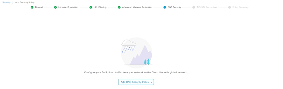
Step 5. Click Next until you get to DNS Security.
Step 6. Click Add DNS Security Policy > Create New.
Step 7. Give a meaningful Policy Name.
Step 8. Click Manage Umbrella Registration to Legacy Network Devices API next to Registration Token.
Step 9. Next to Local Domain Bypass List, add the domain(s) to be excluded from the Umbrella tunnel.
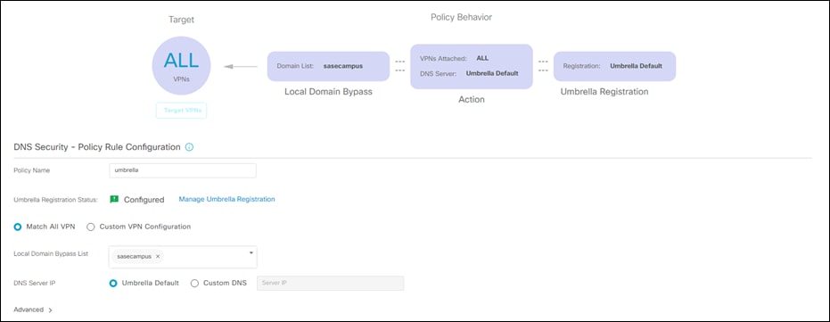
Step 10. Click Save DNS Security Policy.
Step 11. Click Next until you get to Policy Summary.
Step 12. Add a meaningful Security Policy Name and Description.
Step 13. Click Save Policy.
Step 14. Navigate to Configuration > Templates > Device and edit the device template for the ISR4461.
Step 15. Under Additional Templates > Security Policy add the newly created DNS policy.
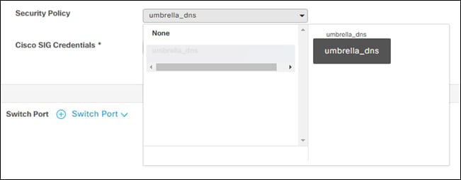
Step 16. Click Update and push changes to the devices.
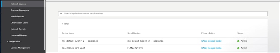
Step 17. To verify connectivity, navigate to Deployments > Core Identities > Network Devices in the Umbrella dashboard. The ISR4461 will show up as a network device and can be used as an identity in DNS policies.
Add Cisco Umbrella DNS policy to Cisco SD-WAN network
At this point, DNS policies configured in Cisco Umbrella can now be applied to the WAN Edge devices.
Step 1. In the vManage Dashboard, navigate to Policies > Management > DNS Policies.
Step 2. Select the policy that was created in a previous section and click Edit Identity.
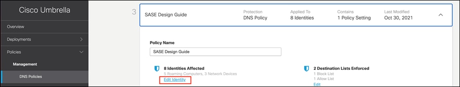
Step 3. Scroll down to Network Devices and select the ISR4461 devices that have been added through the API.
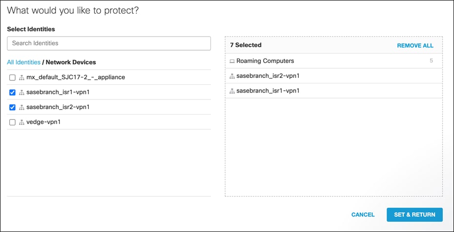
Step 4. Click Set & Return on the identity page and Save the policy.
Web Policies
A cloud-based web proxy or SWG provides security functions such as malware detection, file sandboxing and dynamic threat intelligence, SSL decryption, app and content filtering, and DLP.
There are two parts to configuring the web policy:
● Configuring a ruleset: enable a ruleset by selecting identities and then configuring ruleset settings to determine protection options for that ruleset.
● Add rules to a ruleset: add rules to set actions (allow, block, and warn) against individual identities and the destination those identities attempt to access.
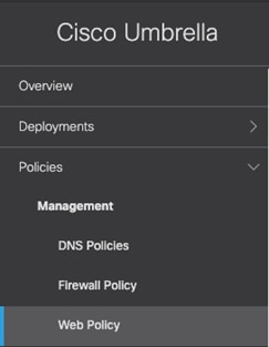
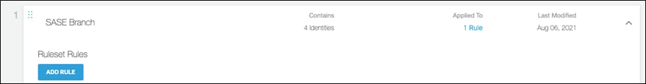
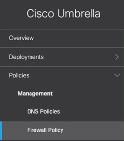
Step 1. In the Umbrella Dashboard, navigate to Policies > Management > Web Policy.
Step 2. Click Add.

Step 3. Expand the newly created rule set.
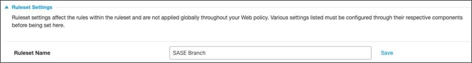
Step 4. Give a meaningful name to the ruleset by clicking the Edit button in the Ruleset Name row. Click Save.
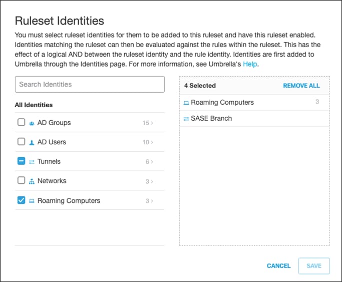
Step 5. Click the Edit button next to Ruleset Identities.
Step 6. Choose the Identity that this ruleset applies to. For this design guide, the identities chosen were the Network Tunnels associated with our branch and all Roaming Computers. Click Save.
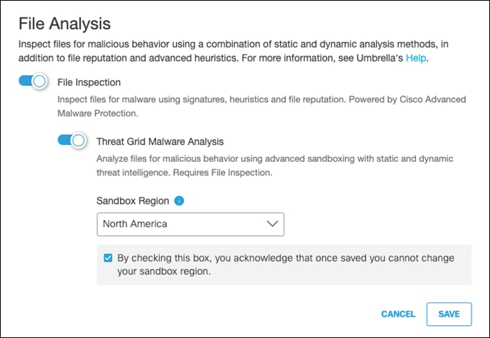
Step 7. Next to File Analysis, click Edit.
Step 8. Enable both File Inspection and Threat Grid Malware Analysis.
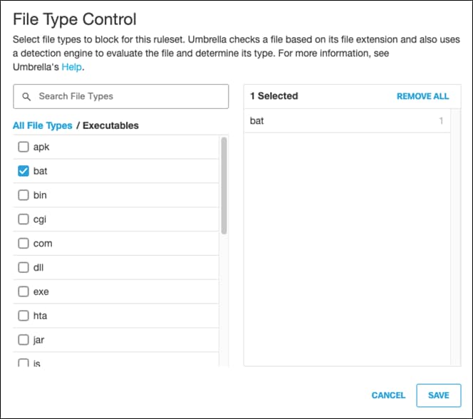
Step 9. Next to File Type Control, click Edit.
Step 10. Choose the file types to block for this ruleset. For validation purposes, Batch files will be blocked. For more information, see Manage File Type Control. Click Save.
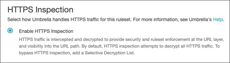
Step 11. Next to HTTPS Inspection, click Edit.
Step 12. Click Enable HTTPS Inspection. Note: A root certificate is required in any circumstances where Umbrella must proxy, and decrypt HTTPS traffic intended for a website. For certificate installation see Appendix A.
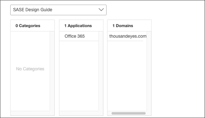
Step 13. Select the Web Selective Decryption List. Note: Umbrella’s Selective Decryption List component excludes selected content categories, applications, and domains from inspection when HTTPS Inspection is enabled for a ruleset. For more information on the excluded list for this design guide, see Appendix B.
Step 14. Click Save.
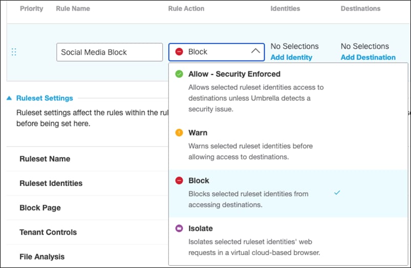
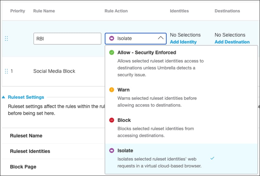
Step 15. Scroll back to the top of the policy and click Add Rule.
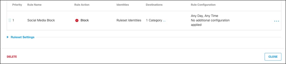
Step 16. Give a meaningful Rule Name. For this rule we will block specified content categories.
Step 17. Under Rule Action, select Block.
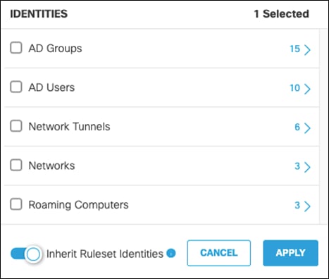
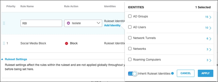
Step 18. Under Identities, click Add Identity and choose the option to Inherit Ruleset Identities. Click Apply.
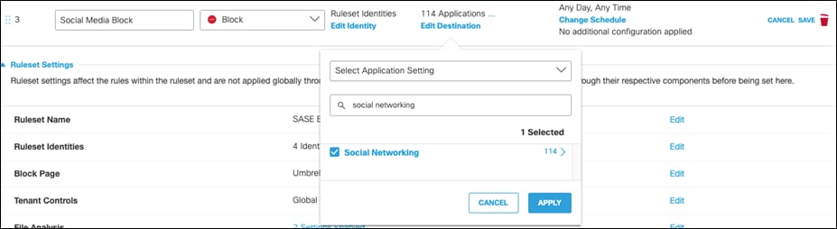
Step 19. Under Destinations, click Add Destination and choose an Application Setting to block. For validation testing, all Social Networking will be selected. Click Apply.
Step 20. Rule Configurations will not be used in this design guide. For more policy options, such as enforcing during a specified time of day, see Add Rules to a Ruleset.
Step 21. Click Save on the rule.
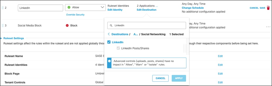
Step 22. Web policies will be enforced on the first match. To allow specific social media sites, such as LinkedIn, create an Allow rule and place it above the Block rule. Note: An alternate approach is to modify the Application Settings for a web policy. This would allow a user to remove LinkedIn from the Social Media category for a given policy. For more information, see Manage Application Settings.
Step 23. At the bottom of the policy, click Close to save the policy.
Cloud Firewall Policies
With Cisco Umbrella’s cloud-delivered firewall, all activity is logged, and unwanted traffic blocked using IP, port, and protocol rules. Rules are automatically applied to any tunnel connected to Umbrella. For this design guide, the firewall will be used to block any peer-to-peer (P2P) traffic such as BitTorrent. BitTorrent is a P2P protocol design to transfer files. Since these networks do not use HTTP(s), they would not fall under web traffic and therefore bypass web inspection.
Step 1. In the Umbrella Dashboard, navigate to Policies > Management > Firewall Policy.
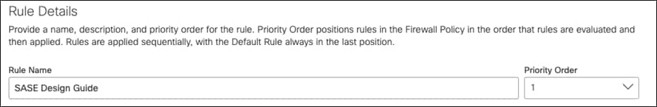
Step 2. Click Add.

Step 3. Give a meaningful Rule Name and apply priority to the firewall rule. Note: Rules are applied sequentially, with the Default Rule always in the last position.
Step 4. Under Applications, click Specify Applications from the drop-down menu.
Step 5. Click the + icon in the search bar and navigate down to P2P. Click to Enable.
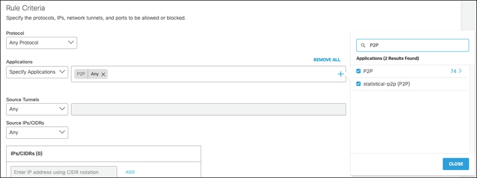
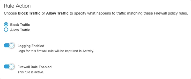
Step 6. Under Rule Action, click Block Traffic and ensure Logging is Enabled.
Step 7. Click Save.
Intrusion Prevention System
IPS, based on SNORT 3 technology, uses signature-based detection to examine network traffic flows and take automated actions to catch and drop dangerous packets before they reach their target. An IPS capability is only as effective as the cyberattack dictionaries. Umbrella IPS uses extensive signatures (40,000+ and growing) from Cisco Talos, the largest private security threat intelligence organization in the world.
Step 1. In the Umbrella Dashboard, navigate to Policies > Management > Firewall Policy.
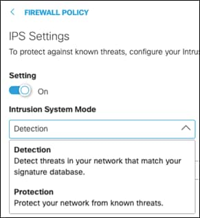
Step 2. Next to Umbrella’s Intrusion Protection System, click Configure.

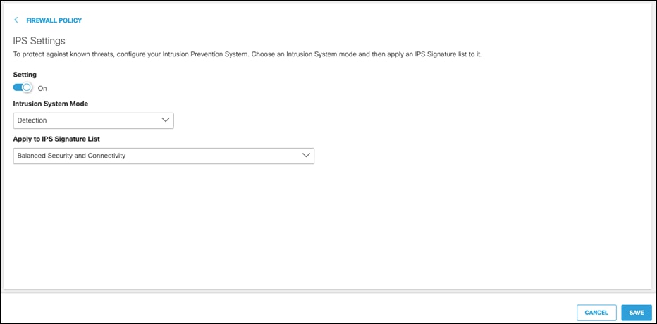
Step 3. Click the Intrusion System Mode dropdown menu and choose either Detection or Protection. Detection mode will not block traffic, only alert on rules. Protection, if a rule is configured to do so, will block based on IPS detection. This design guide is configured with Detection.
Step 4. Click the Apply to IPS Signature List dropdown menu and choose the level of protection required:
● Connectivity Over Security places emphasis on network connectivity and throughput at the possible expense of security
● Balanced Security and Connectivity attempts to balance network connectivity and security to keep users secure while being less obtrusive toward normal traffic. Note: This design guide is configured using Balanced Security and Connectivity
● Security Over Connectivity results in traffic to be inspected more deeply and more rules are evaluated
● Maximum Detection places all emphasis on security, such that network connectivity and throughput are compromised. Only select this setting when total protection is required
Step 5. Click Save.
Data Loss Prevention
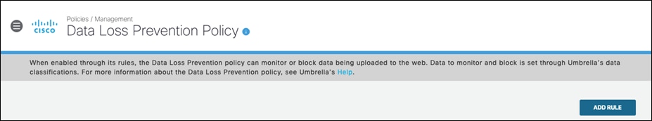
The DLP policy monitors content classified as personally identifiable or sensitive information. When necessary, content is blocked from an upload or a post. Rules are added to the policy to define what traffic to monitor (identities and destinations), the data classifications that require monitoring, and whether content should be blocked or only monitored. For example, an office may want to monitor its network for file uploads that include credit card numbers, because the uploads are a breach of company privacy and security policies. A rule designed to monitor the network and uploads to domains can block these files.
Note: HTTPS Inspection must be enabled (see Appendix A for details on the Umbrella root certificate) on the web policy ruleset where this DLP policy applies. DLP cannot be applied to encrypted traffic. For destinations that have been excluded from the decryption list, such as Office 365, it is recommended to use an API based solution such as Cisco Cloudlock or use the DLP policies included in Office 365.
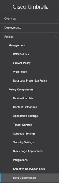
Step 1. In the Umbrella Dashboard, navigate to Policies > Policy Components > Data Classification.
Step 2. Click Add.

Step 3. Give a meaningful Data Classification Name.
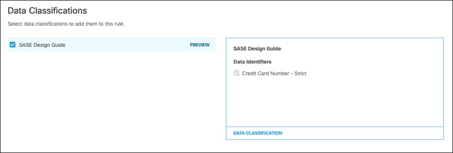
Step 4. Select Built-in-Data Identifiers and choose the identifiers. For this design guide, Credit Card Number – Strict is selected. For a full list of identifiers, along with their description, see Built-In Data Identifiers. Additionally, to create custom identifiers such as classified project code names, see Create a Custom Dictionary.
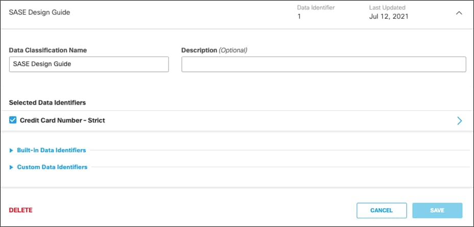
Step 5. Click Save.
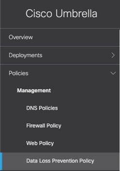
Step 6. Navigate to Policies > Management > Data Loss Prevention Policy.
Step 7. Click Add Rule.
Step 8. Give a meaningful Rule Name.
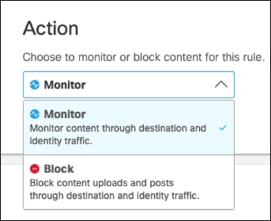
Step 9. Choose an Action. This guide will Monitor traffic that matches the DLP policy.
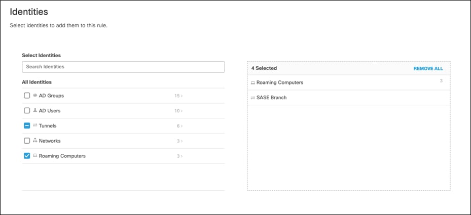
Step 10. Under Identities, select identities that will be monitored. This design guide will monitor all Roaming Computers and the network tunnel from our Branch.
Step 11. Under Data Classifications, select the data classification that was created in the previous steps.
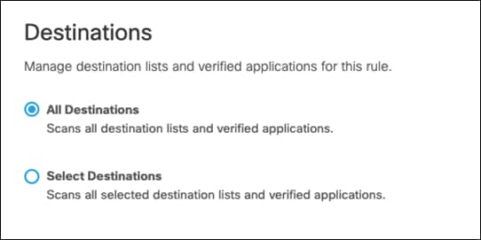
Step 12. Under Destinations, select All Destinations. Note: If blocking traffic, not all destinations are supported. The level of support for each application can be found at Supported Applications.
Step 13. Click Save.
Remote Browser Isolation (RBI)
RBI protects identities from potential malware and other threats by redirecting browsing to a cloud-based host. Destinations supported by an RBI add-on can be isolated when added to a rule in a Web policy’s ruleset. When you add a rule and choose Action > Isolate, the selected destination in the rule will create a remote browser when users attempt to access those destinations. Instead of blocking identities from the destination endpoints, a cloud-based browser hosts the browsing session for that destination.
Step 1. In the Umbrella Dashboard, navigate to Policies > Management > Web Policy. We will modify the policy created in a previous section.
Step 2. Click the policy in which RBI will apply.

Step 3. Click Add Rule.
Step 4. Give a meaningful Rule Name.
Step 5. Under Rule Action, select Isolate.
Step 6. Under Identities, click Add Identity and choose the option to Inherit Ruleset Identities.
Step 7. Under Destinations, click Add Destination. For this validation, RBI will be used to access Dropbox so that if any malware is accidentally downloaded when browsing a cloud storage website, it does not get downloaded onto the client’s machine. Click Apply.
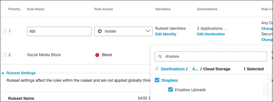
Step 8. Click Save on the rule.

Step 9. Click Close on the policy.
Cisco Duo Network Gateway (DNG) Application protection
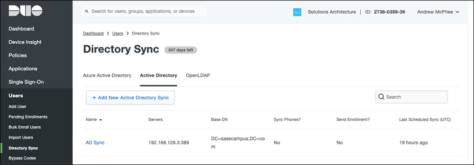
Since many large organizations already rely on an on-premises Active Directory (AD) server, OpenLDAP Directory, or a cloud-hosted Azure AD directory to manage their users, Duo offers tools to import users and groups from those identity stores into Duo, with the option of automatically sending an enrollment email to every user imported without an attached phone who has a valid email address.
To automatically enroll users from AD into Duo, see Synchronizing Users from Active Directory. For this design guide, a group called SASECampus was created, and an option was chosen to only synchronize users who belong within that group.
Now that a group of users has been classified, applications in Duo can be restricted to only allow members of the group to access.
Step 1. In the Duo Dashboard, navigate to Applications.
Step 2. Select the application used to enforce 2FA on the VPN.

Step 3. Scroll down to the bottom of the page and beside Permitted Groups, click the checkbox for Only allow authentication from users in certain groups.
Step 4. In the search bar, choose the group(s) that should have access to the VPN. All other users will be denied.
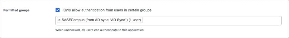
Step 5. Click Save.
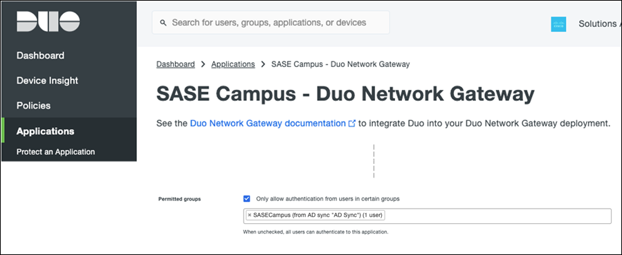
Step 6. Repeat the process for the application protections for DNG.
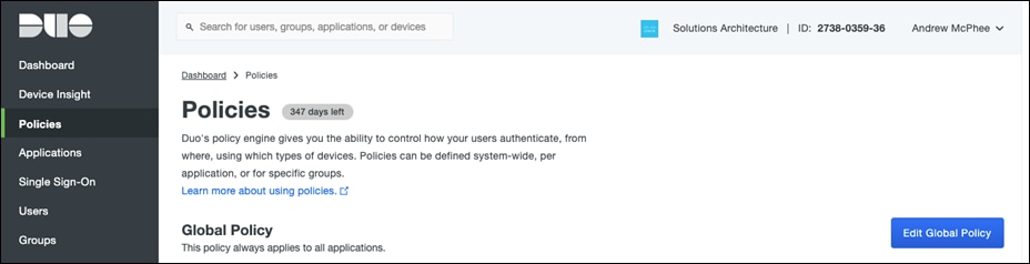
The Global Policy in Duo applies to all applications. If certain applications require policy and controls that differ from the Global policy, you can create a Custom Policy and assign it to those applications (for example, VPN policy may allow access from non-trusted devices, but DNG may require Cisco Secure Endpoint). For this design guide, since we are already restricting policy access at a user level, the Global Policy will be configured and applied to all applications protected by Duo (i.e., remote access VPN and the Duo Network Gateway).
Step 1. In the Duo Dashboard, navigate to Policies.
Step 2. Click Edit Global Policy.
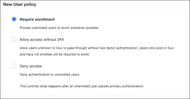
Step 3. Under New User policy, click Require enrollment (default).
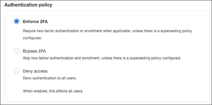
Step 4. Under Authentication policy, click Enforce 2FA (default).
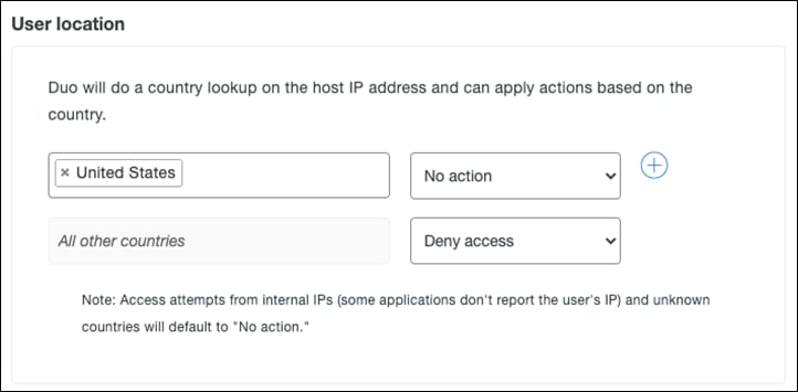
Step 5. Under User location, enter all countries that you expect to receive authentication from and choose No action from the dropdown list. For all other countries choose Deny access. Note: Access attempts from Internal Ips and unknown countries will default to “No action”.
Step 6. Under Trusted Endpoints, click Require endpoints to be trusted and Allow AMP for Endpoints to block compromised endpoints. This allows Duo to block devices that have been deemed to be compromised by Cisco Secure Endpoint.
Note: To create the integration between Duo and Cisco Secure Endpoint, see Trusted Endpoints – Cisco AMP for Endpoints.
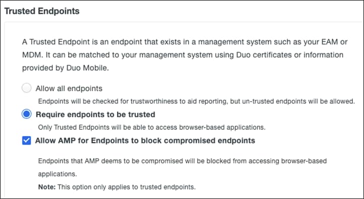
Step 7. Under Device Health application, choose if you want your application to require the Duo Device Health application. This allows us to restrict user access for device metrics such as if the device firewall is off or if a password has not been set on the device. For this design guide, we will click Don’t require users to have the app. For more information, see Enabling the Device Health Application Policy.
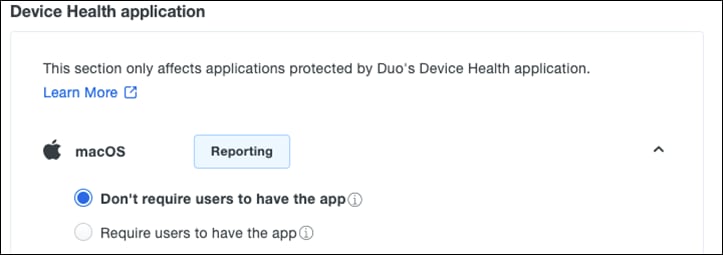
Step 8. Under Remembered devices, click Do not remember devices (default). Remembered devices allow users to skip subsequent 2FA requests.
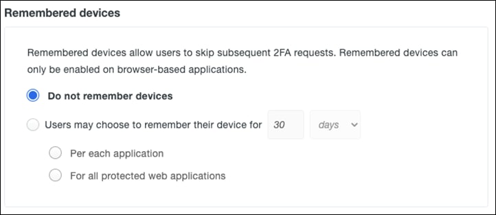
Step 9. Under Operating systems, leave all settings as default. This section allows us to do version control, such as forcing users to update their operating system to a specified version or by completely blocking an operating system from the network.
Step 10. Scroll down to Authentication methods and choose which methods to use for authentication. For this design guide, only Duo Push and SMS passcodes will be enabled.
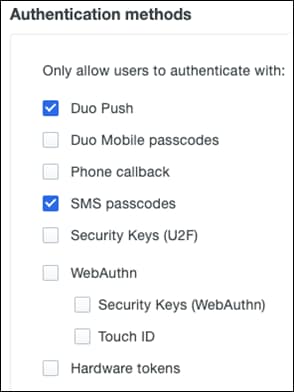
Step 11. The remaining policies refer to enforcement of specific smartphone features. Smartphone access is out of scope for this design guide. For more information on configuring these policies, see Policy & Control.
Step 12. Click Save Policy.
Cisco Secure Endpoint contains a comprehensive database of every file that has ever been seen and maintains a corresponding good or bad disposition. As a result, known malware is quickly and easily quarantined at the point of entry without any processor-intensive scanning. For this design guide, custom policies will not be created, and Secure Endpoint alerts will be triggered using the EICAR file.
NOTE: EICAR is safe to pass around because it is not a virus and does not include any fragments of viral code. It is a file that has been created for Anti-virus products to react to for test purposes. Cisco Umbrella also blocks access to this file.
For a more comprehensive analysis of both Secure Endpoint and Secure Malware Analytics, see Cisco Breach Defense Design Guide.
Cisco Duo Single Sign-On is a cloud hosted SAML identity provider that adds two-factor authentication to popular clous services like Salesforce and Microsoft 365 using SAML 2.0 federation. This design guide will use Microsoft 365 for testing and validation.
Cisco Duo authenticates your users using existing on-premises AD credentials and prompting for two-factor authentication before permitting access to Microsoft 365. The solution requires deployment of the Duo Authentication Proxy on your internal network to verify primary logon credentials against AD. End users will sign in and perform 2FA at Duo’s cloud-hosted SSO service, and do not contact the on-premises authentication proxy servers directly.
For step-by-step deployment, see Duo SSO for Microsoft 365.
Converge - Deployment
Cisco ThousandEyes’ global vantage points are Linux-based software agents that allow users to run a variety of layered monitoring tests, to gain insight into network and application performance and user experience.
Cloud and Enterprise Agents are hosts containing Cisco ThousandEyes software capable of running instant or scheduled tests and device discoveries. The main (and almost only) difference between Cloud and Enterprise Agents is who deploys and manages them. Cloud Agents are deployed by Cisco ThousandEyes, on many locations across the globe, instantly available for your new tests. Enterprise Agents, on the other hand, are deployed by you, our customer, in locations of interest (branch offices for example). For this design guide, an Enterprise Agent will be installed in the branch network.
For step-by-step installation of the ThousandEyes enterprise agent, see installing the enterprise agent. For this design guide, an enterprise agent was installed as a container on the ISR4461 in the branch network. For further details see Extended Visibility with Cisco SD-WAN and Cisco ThousandEyes.
Note: Communication between the enterprise agent and the cloud will flow through Umbrella which has been configured to proxy all web traffic. As a result, the domain for ThousandEyes should be added to the selective decryption list so communication between agents and dashboard are not proxied.
Add Cisco ThousandEyes to the Selective Decryption List in Cisco Umbrella
Step 1. In the Umbrella Dashboard, navigate to Policies > Policy Components > Selective Decryption Lists.
Step 2. Click the dropdown button next to the list that is attached to the web policy.
Step 3. In the Domains tab, click Add.
Step 4. Type thousandeyes.com and click Add.
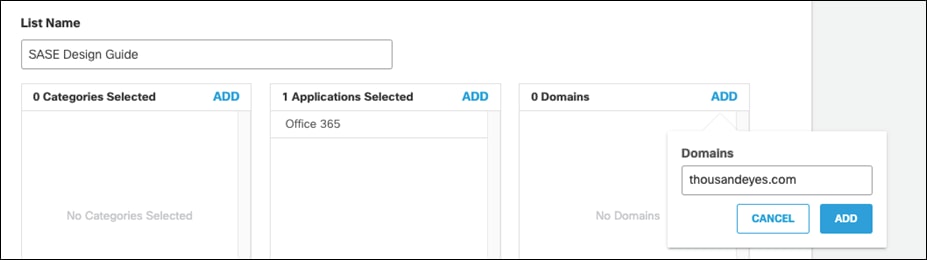
Step 5. Save the policy.
Endpoint Agents are your Windows or macOS workstations that have ThousandEyes Endpoint Agent software installed. These agents, whenever they are present in one of the defined networks, collect network and application layer performance data as your users are accessing websites or applications on configured domains. In addition to that, Endpoint Agents provide basic support for running scheduled tests. Pulse version of Endpoint Agents are also available dedicated to running scheduled tests, these can be installed on customer hosts.
For a step-by-step installation of the ThousandEyes endpoint agent, see installing the endpoint agent. For this design guide, an endpoint agent was manually installed by directly downloading the agent on to the device. To install on multiple devices, a group policy can be created in Active Directory.
Cisco ThousandEyes Tests
ThousandEyes tests are classified into categories based on layers of operation:
● Routing Layer tests provide methods for collecting internet routing-related information.
● Network Layer tests measures network performance and path between agent and a target device.
● DNS Layer tests provide record validation and service performance metrics.
● Web Layer tests touch on various web technologies starting from the most basic measurement of availability of web server all the way up to performing precision transactions on a target.
● Voice Layer tests look at whether a connection can be established, as well as testing the exchange of packets after the connection is made.
This design guide will focus attention on DNS and Web layer testing.
Step 1. In the ThousandEyes Dashboard, navigate to Cloud & Enterprise Agents > Test Settings.
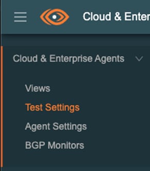
Step 2. Click Add New Test.
Step 3. Using the default Web > HTTP Server test, add the URL for Salesforce.
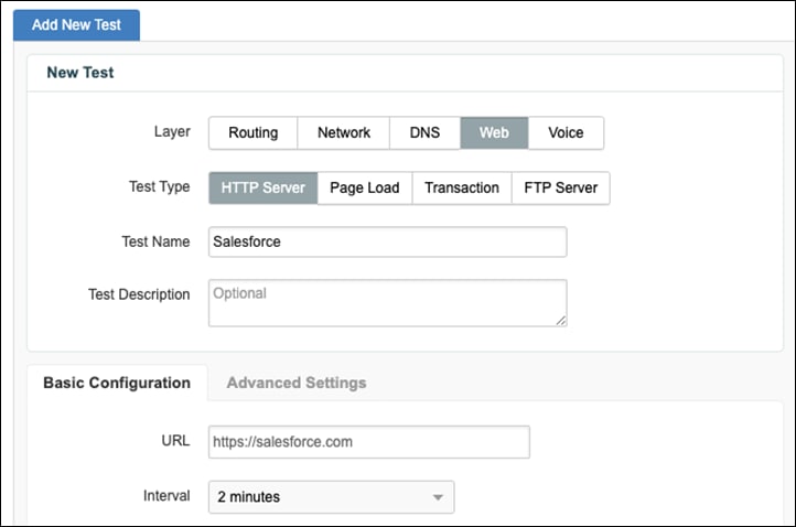
Step 4. In the Agents drop-down menu, click the Enterprise label and select the ISR4461 installed in the branch network.
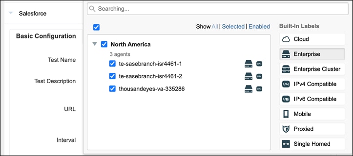
Step 5. Additionally, add some Cloud Agent connections for latency comparisons with the branch.
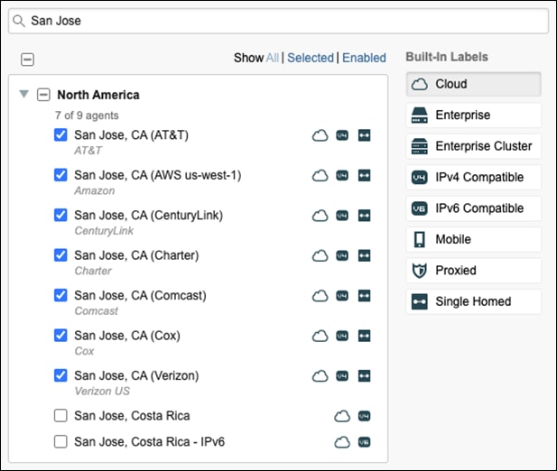
Step 6. In the Advanced Settings tab, click the checkbox next to Verify Content.
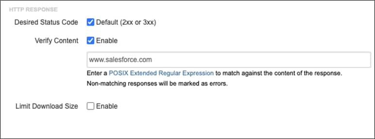
Step 7. In the textbox, enter the value www.salesforce.com. Note: This extra validation is added when sending tests through the Umbrella web proxy. When content is blocked, Umbrella returns a blocked content page which results in a 200-status code which would normally indicate to the client that the connectivity has succeeded. We want the ThousandEyes test to fail on policy block, therefore we must check that the content is valid.
Step 8. Click Create New Test.
Step 9. Repeat for each test. For this design guide, the following additional tests were created
● http://app.cvdtest.net:3000 (private application in the data center)
Step 10. To create a DNS test, navigate to Cloud & Enterprise Agents > Test Settings and click Add New Test.
Step 11. Click the DNS Layer and choose DNS Server as the Test Type.
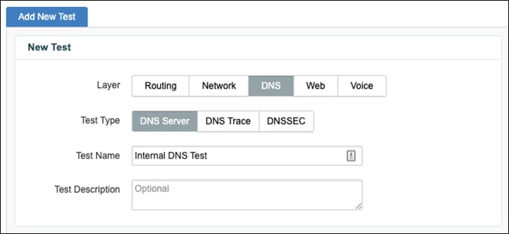
Step 12. Under Basic Configuration, choose a Domain that is commonly accessed by the organization.
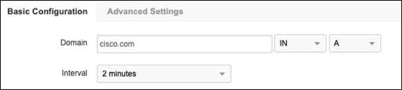
Step 13. In the Agents drop-down menu, choose the ISR4461 located in the branch network.
Step 14. Enter the DNS Server IP address for the private network.
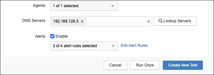
Step 15. Click Create New Test.
Step 16. Click Add New Test, but this time choose the Cloud Agent(s) for your region and enter the DNS Server addresses for Umbrella. This allows us to check the availability of Umbrella outside the local network in the case that the DNS is failing internally.
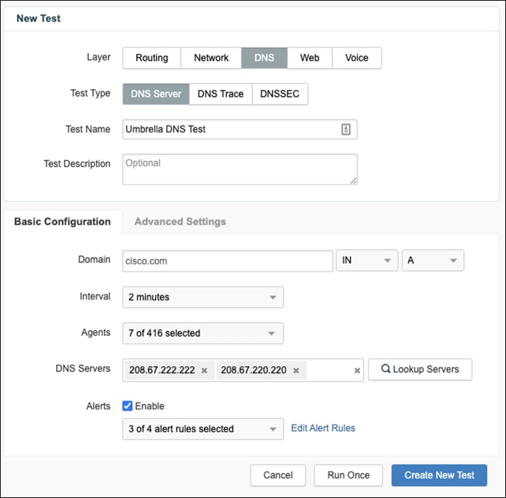
Note: All tests can be repeated for the endpoint agents located in the network.
This deployment guide will primarily focus on the unified visibility and SSO capabilities of Cisco SecureX, by demonstrating the integrations it has with other products in the Cisco security portfolio. Other capabilities of SecureX, such as threat response and the dashboard ribbon can be explored further in the Cisco Breach Defense Design guide.
Cisco Umbrella
Step 1. In the Umbrella Dashboard, navigate to Investigate > API Keys.
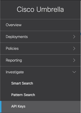
Step 2. Click Create New Token.
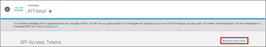
Step 3. Enter a meaningful Title and click Create.
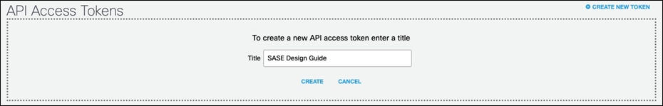
Step 4. Take note of the Investigate API Token.
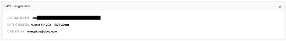
Step 5. In the Umbrella Dashboard, navigate to Admin > API Keys.
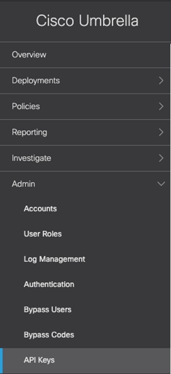
Step 6. If an Umbrella Reporting API Key does not already exist, click Create. Note: Only one instance of the API Key can exist for each function.

Step 7. Under What should this API do? click the Umbrella Reporting audio button and click Create.
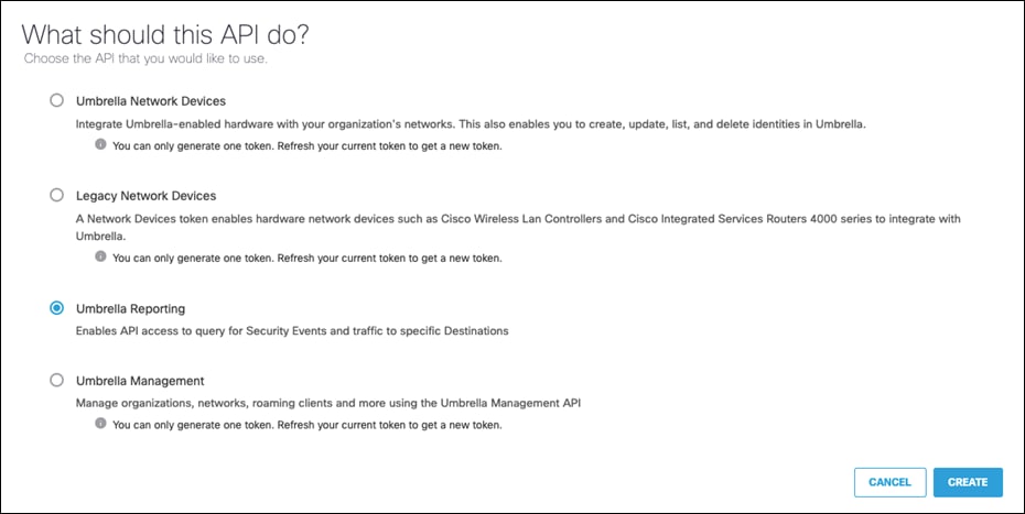
Step 8. Take note of both the Reporting API Key and API Secret. Note: The secret will only be shown once. Make sure to store it in a secure location for future use.
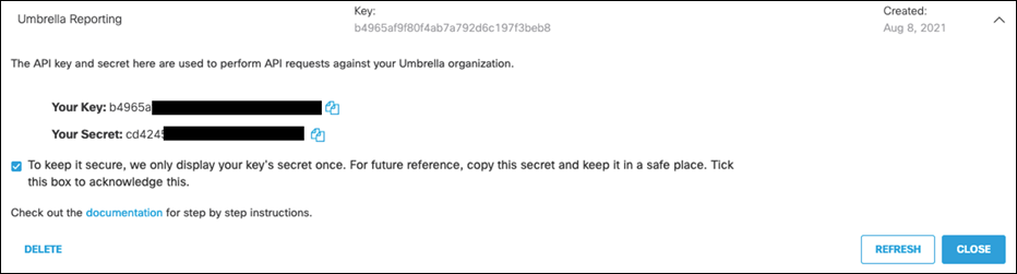
Step 9. In the Umbrella Dashboard, navigate to Policies > Policy Components > Integrations.
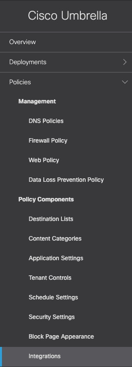
Step 10. Click Add.

Step 11. Give a meaningful Integration Name and click Create.
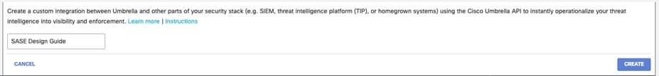
Step 12. Click the newly created integration, check the Enable box and click Save.
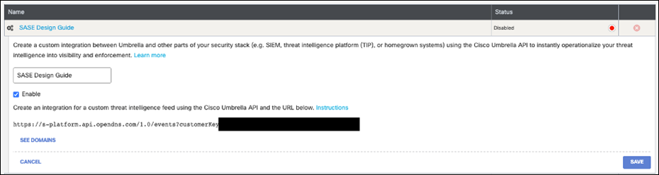
Step 13. Click the integration to display the Custom Umbrella Integration URL.
Step 14. In the SecureX Dashboard, navigate to Integration Modules > Available Integration Modules.
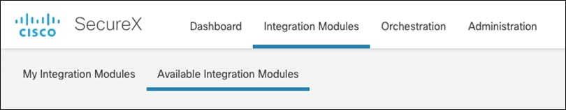
Step 15. Under Cisco Products, search for Umbrella and click + New Module.
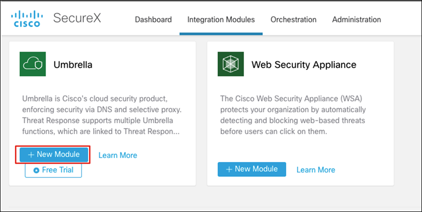
Step 16. Enter a meaningful Integration Module Name.
Step 17. Using the values generated in the previous steps, enter the required fields in the Investigate, Enforcement and Reporting forms.
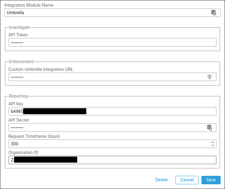
Step 18. Click Save.
To enable SSO with SecureX in Umbrella, make sure the SecureX account is the same across all environments. If the user is not in the Umbrella organization, please add it under Admin > Accounts. Once completed, follow these deployment steps to enable SSO:
Step 1. In the Umbrella Dashboard, navigate to Admin > Authentication.
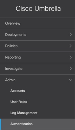
Step 2. Under SAML Dashboard User Configuration, click Configure.
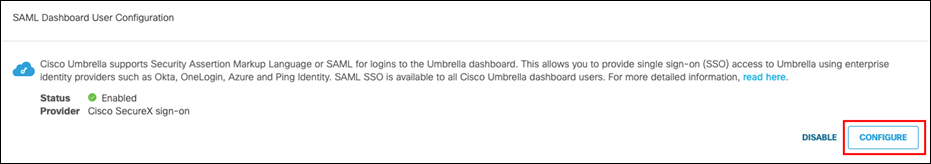
Step 3. Select Cisco SecureX sign-on and click Next.
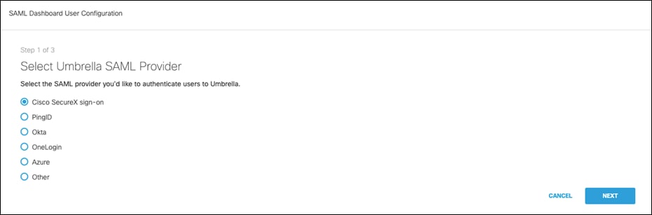
Step 4. Click Test Configuration to verify the setup and click Next.
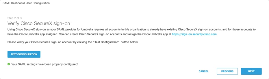
Step 5. Agree to the conditions and click Save and Notify Users.
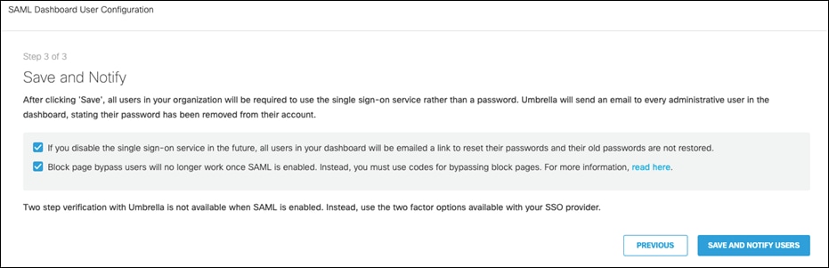
Cisco Secure Endpoint
Step 1. In the Cisco Secure Endpoint Dashboard, navigate to Accounts > API Credentials.
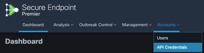
Step 2. Click New API Credential.
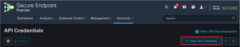
Step 3. Enter a meaningful Application name and choose the desired Scope. Note: This design guide will only require the Read-only scope, however, the Read & Write scope has been chosen for readers who will also be using the Breach Defense guide and would like to take response actions with Secure Endpoint. Click Create.
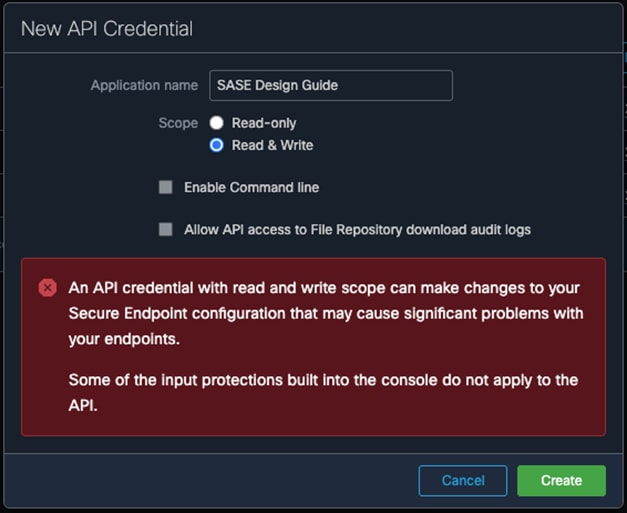
Step 4. From the API Key Details page, copy both the 3rd Party API Client ID and the API Key. Note: Do not close the tab without retrieving these values. The API key is not retrievable once the tab is closed.
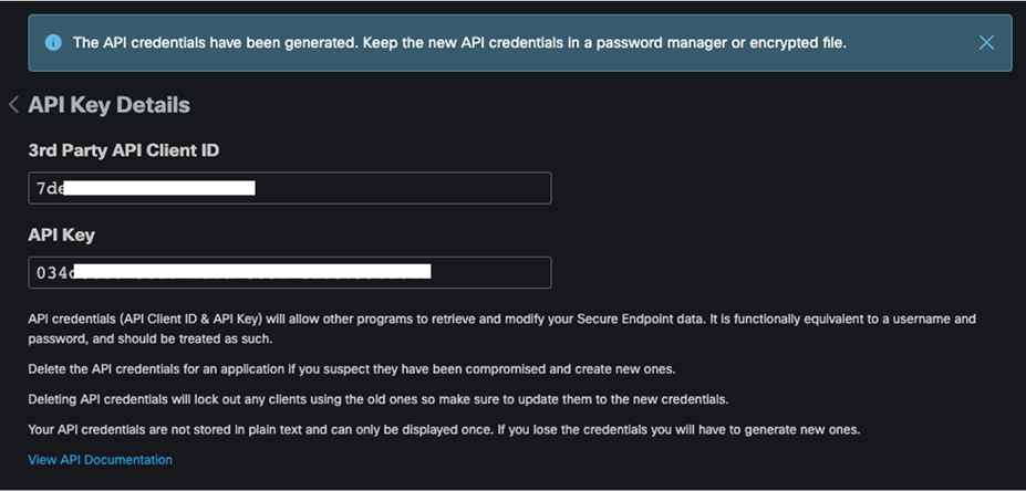
Step 5. In the SecureX Dashboard, navigate to Integration Modules > Available Integration Modules.
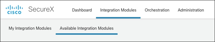
Step 6. Under Cisco Products, search for AMP for Endpoints (former name to Secure Endpoint) and click + New Module.
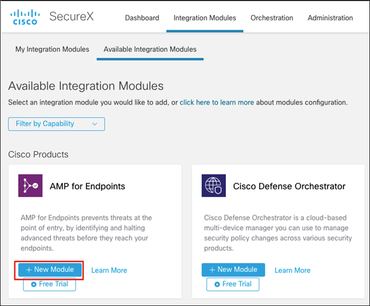
Step 7. Add the 3rd Party API Client ID and the API Key from the previous steps.
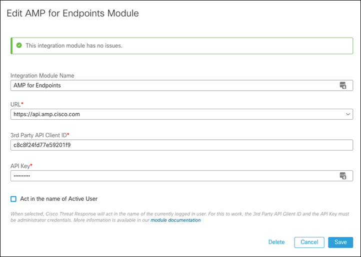
Step 8. Click Save.
Note: SecureX SSO was enabled by default for the organization used in validating this design. If SSO is not enabled under Accounts > Organization Settings in the Secure Endpoint Dashboard, see Enabling Cisco SecureX Sign-On for Secure Endpoint.
SecureX Dashboard
Step 1. In the SecureX Dashboard, click Customize.

Step 2. Give a meaningful Dashboard Name.
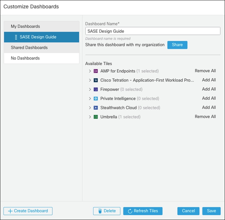
Step 3. Under Available Tiles, expand both AMP for Endpoints and Umbrella.
Step 4. Choose the tiles that you would like to add to the SecureX Dashboard and click Save.
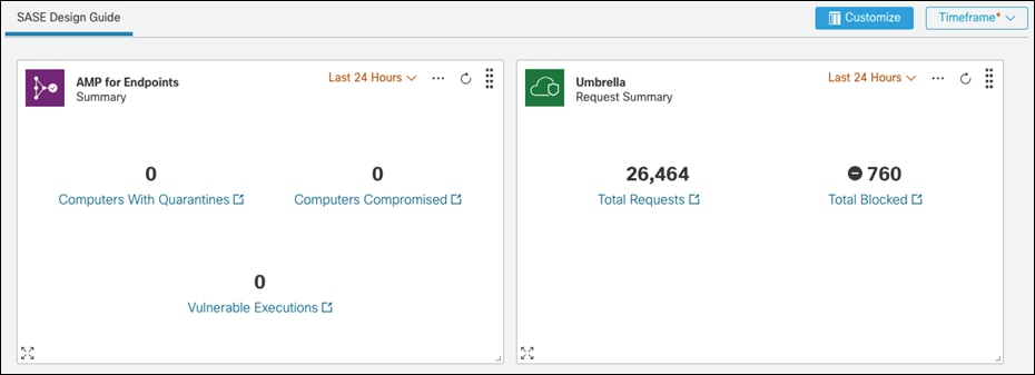
Remote Worker to Public Application (SaaS)
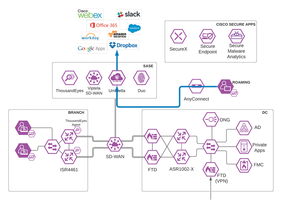
Roaming User to SaaS application through Umbrella
Validation Test #1 – Umbrella Roaming Client successfully installed with AnyConnect
Step 1. On a roaming device from the AnyConnect installation steps, open AnyConnect Secure Mobility Client.
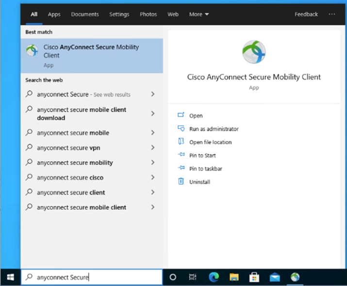
Step 2. When on a network other than the office network, verify that Umbrella Roaming is active.
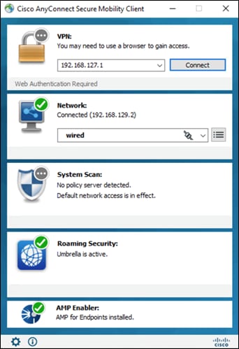
Step 3. Also verify that Cisco Secure Endpoint (AMP Enabler) has been installed as part of AnyConnect.
Step 4. In any browser, navigate to https://welcome.umbrella.com to verify that you are using Umbrella DNS.
Validation Test #2 – Umbrella Content Filtering is being applied
Step 1. In any browser, navigate to https://facebook.com. The Umbrella block page should be returned.

Step 2. In any browser, navigate to https://linkedin.com. Access to the site should be granted.
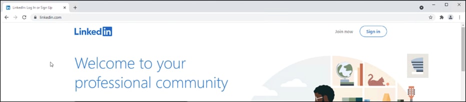
Step 3. In the Umbrella Dashboard, navigate to Reporting > Core Reports > Activity Search.
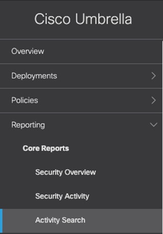
Step 4. In the Filters tab, check the Blocked box under Response and click Apply.

Step 5. Verify the entry for Facebook has been logged.
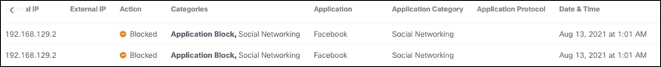
Validation Test #3 – Umbrella DLP Policies have been triggered
Step 1. In any browser, navigate to any cloud storage site. This design guide will use Box.

Step 2. Upload a file containing random US credit card numbers. Example below.
6011 1834 5527 3209
Discover
6011 2150 2716 5024
Discover
4328 1373 5449 1554
Visa
5430 3563 9033 0772
MasterCard
6011 0430 8746 4644
Discover
6011 6766 2381 3665
Discover

Step 3. In the Umbrella Dashboard, navigate to Reporting > Additional Reports > Data Loss Prevention.

Step 4. An event will be created for the file that was uploaded.

Validation Test #4 – Umbrella Remote Browser Isolation
Step 1. In any browser, navigate to https://dropbox.com (the site chosen for our DLP policy).
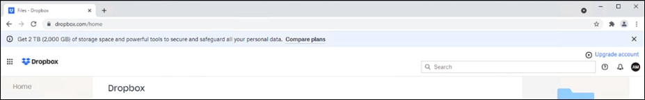
Step 2. Download any file.
Step 3. The file will download and open in a remote browser, which can be confirmed by looking at the URL of the opened file.
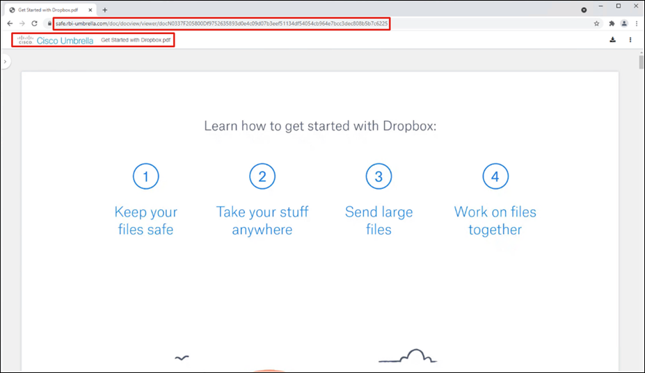
Step 4. In the Umbrella Dashboard, navigate to Reporting > Core Reports > Activity Search.
Step 5. In the Filters tab, check the Isolated box under Isolate and click Apply.
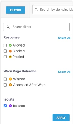
Step 6. Verify that the session to Dropbox has been logged.
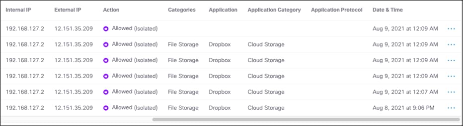
Validation Test #5 – Intrusion Prevention System
Step 1. Open a command prompt and type the following:
curl http://3.25.228.160/test.emf
Step 2. In the Cisco Umbrella dashboard, navigate to Reporting > Core Reports > Activity Search.
Step 3. Under IPS Signature filters, click Select All and then Apply.
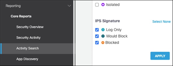
Step 4. The activity log should show an IPS log that triggered based on a Microsoft emf file download request.

Validation Test #6 – Duo SSO for SaaS Applications
Step 1. In any browser, navigate to https://login.microsoftonline.com and sign into your Microsoft 365 domain.
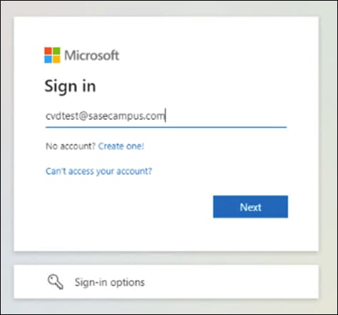
Step 2. Verify that the sign-on process is routed to Cisco Duo SSO.
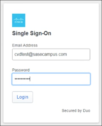
Step 3. Verify your identity with Cisco Duo MFA.
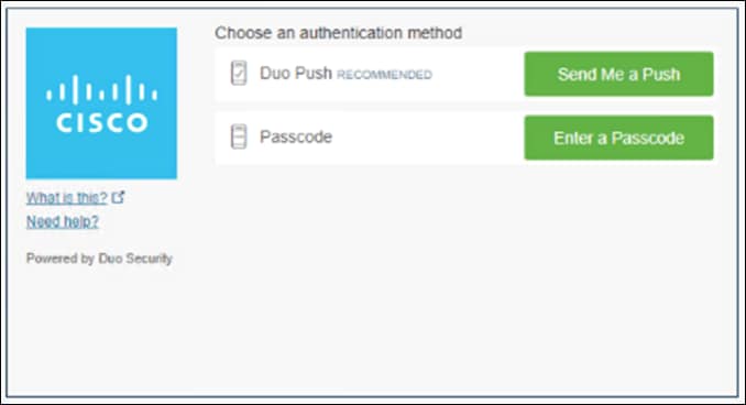
Step 4. In the Duo Dashboard, navigate to Reports > Authentication Log and verify an SSO event was logged.
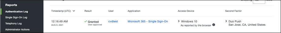
Remote Worker to Private Application (VPNless)
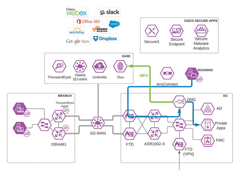
Roaming User to Private Application through Duo Network Gateway
Validation Test #1 – Verify Private Application can be reached from Public Internet
Step 1. Using any browser on a client off network, navigate to the URL that was assigned to your application in the DNG installation.

Step 2. Sign into Cisco Duo SSO.
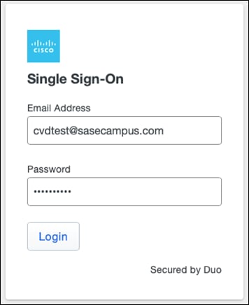
Step 3. Verify your identity with Cisco Duo MFA.

Step 4. The HTTPS should be proxied to the private application.
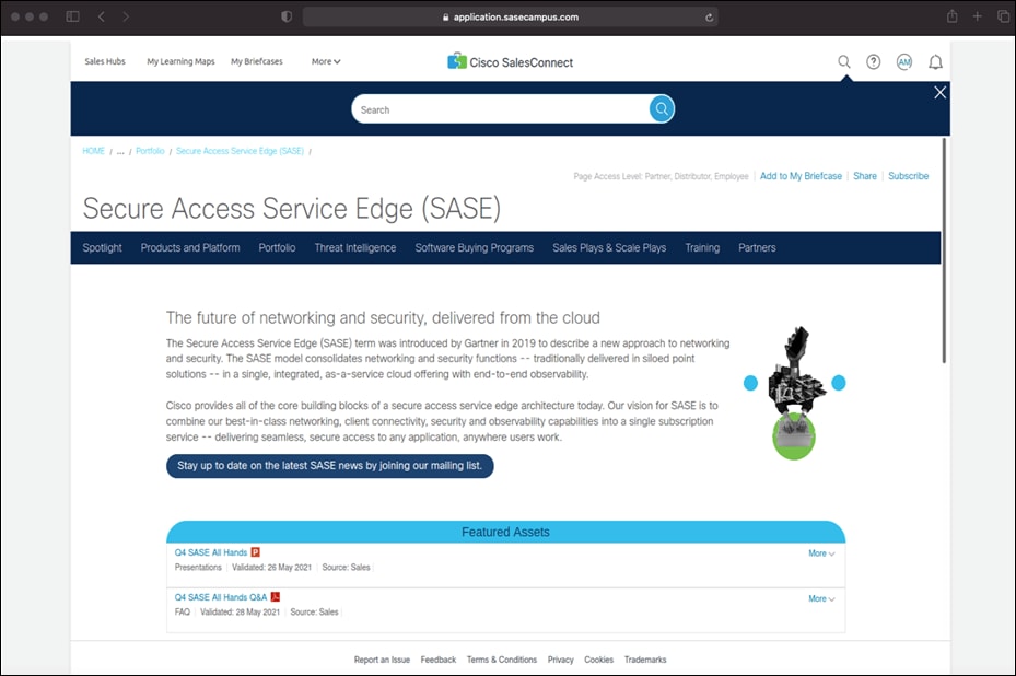
Step 5. In the Duo Dashboard, navigate to Reports > Authentication Log.
Step 6. Verify that the user connection has been logged.
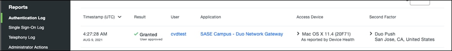
Validation Test #2 – Verify Application is restricted by User
Step 1. Using any browser on a client off network, navigate to the URL that was assigned to your application in the DNG installation.
Step 2. Sign into Cisco Duo SSO using an account that was not added to the Duo Group Policy.
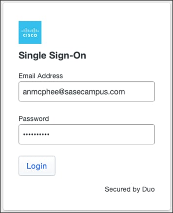
Step 3. Duo will return a page to show that access has been denied.

Validation Test #3 – Verify Application is restricted by User location
Step 1. On the client machine, use a VPN to connect to a location outside of the allowed locations. For this design guide, only devices in the United States are allowed access.
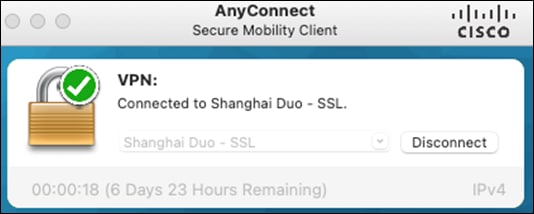
Step 2. Using any browser, navigate to the URL that was assigned to your application in the DNG installation.
Step 3. Sign into Duo SSO.
Step 4. Duo will return Login request denied.
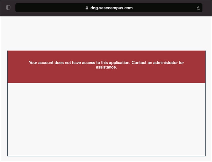
Step 5. In the Duo Dashboard, navigate to Reports > Denied Authentications.
Step 6. Scroll down to Result Reasons and a Location restricted reason will be present.
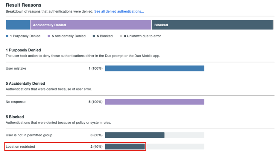
Validation Test #4 – Verify Application is restricted by Device Health
Step 1. On a trusted device, trigger a Cisco Secure Endpoint alarm. Example below.
Netsh interface portproxy add v4tov4 listenport-8001 connectport=80 connectaddress=127.0.0.1
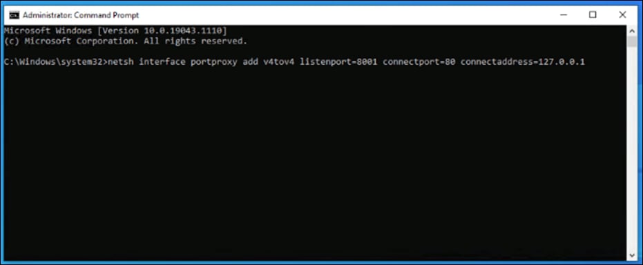
Step 2. In Cisco Secure Endpoint Dashboard, navigate to Events.
Step 3. Verify that an Indicator of Compromise (IoC) has occurred on the machine.
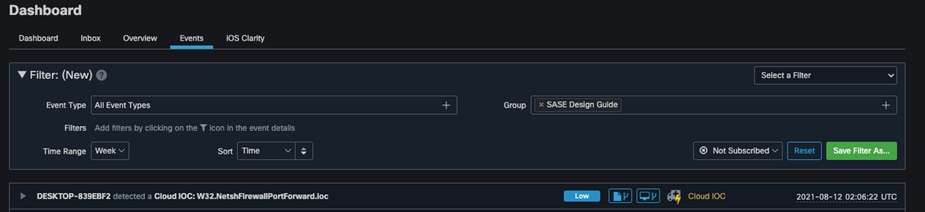
Step 4. Using any browser on the trusted endpoint, navigate to the URL that was assigned to your application in the DNG installation. Duo prompt should return “We’re sorry. Access is not allowed.”.
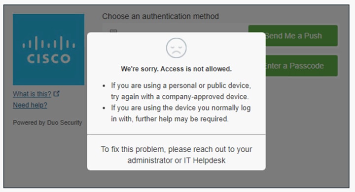
Remote Worker to Private Application (VPN)
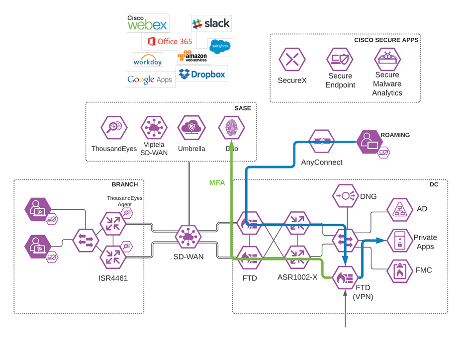
Roaming User to Private Application through VPN
Validation Test #1 – Verify User can connect to VPN
Step 1. Using AnyConnect, connect to the IP/FQDN of the VPN firewall in the data center.
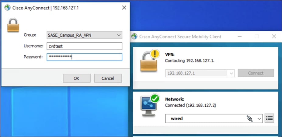
Step 2. Verify your identity with Cisco Duo MFA.
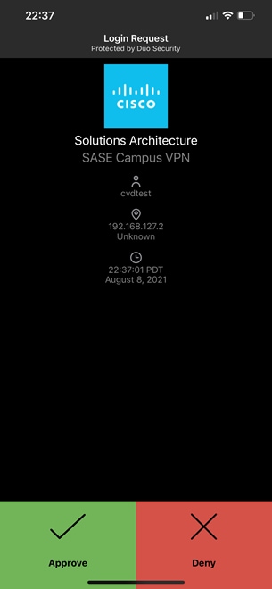
Step 3. Once connected to VPN, navigate to an application on the internal network.
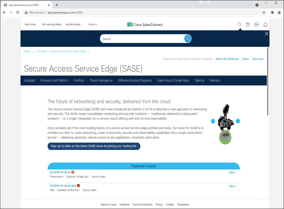
Validation Test #2 – Verify VPN access is restricted by Duo Policy
Step 1. Using AnyConnect, connect to the IP/FQDN of the VPN firewall in the data center.
Step 2. Use log-on credentials for a user who is not part of the VPN user group, as per policies created in the deployment steps.
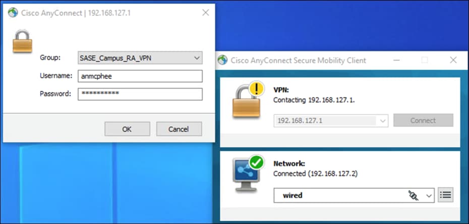
Step 3. AnyConnect should return a failed login attempt.
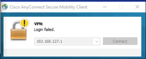
Step 4. In the Duo Dashboard, navigate to Reports > Authentication Log.
Step 5. The Denied attempt should be logged for the user.
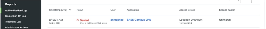
Note: All other Duo policy tests work for the private application as they have in the public application validation tests.
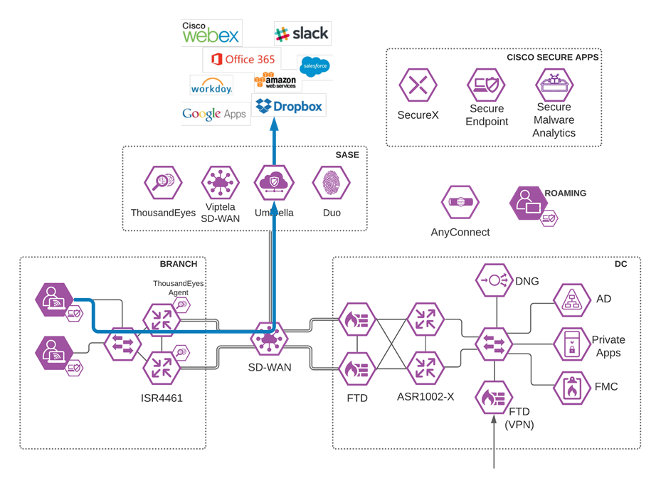
Branch User to SaaS Application through Umbrella
Validation Test #1 – Verify Internet traffic flows through Umbrella
Step 1. On a device in the branch network, navigate to any website.
Step 2. In Umbrella, navigate to Reporting > Core Reports > Activity Search.
Step 3. Verify there is an activity record to the chosen site with the identity of the network tunnel present.
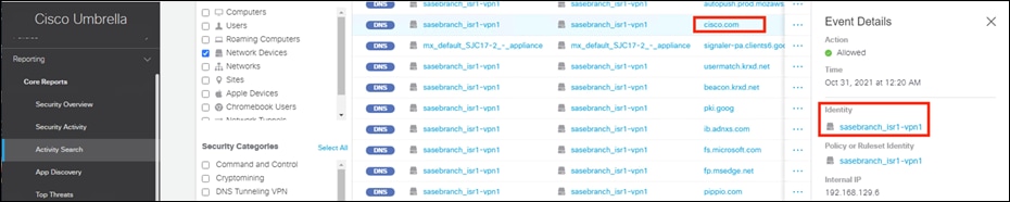
Step 4. Since the WAN edge devices are in a HA pair, disconnect the WAN connection of the primary device in the branch.
Step 5. On the same branch device, generate more internet traffic.
Step 6. In the Umbrella Dashboard, in the Reporting > Core Reports > Activity Search section, there should be activity records from the backup network device.

Validation Test #2 – Umbrella Content Filtering is being applied
Step 1. In any browser, navigate to https://facebook.com. The Umbrella block page should be returned.
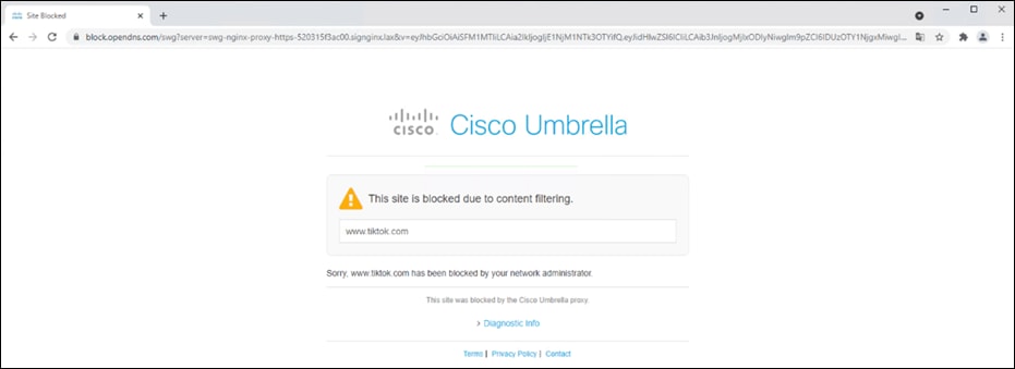
Step 2. In any browser, navigate to https://linkedin.com. Access to the site should be granted.

Step 3. In the Umbrella Dashboard, navigate to Reporting > Core Reports > Activity Search.

Step 4. In the Filters tab, check the Blocked box under Response and click Apply.
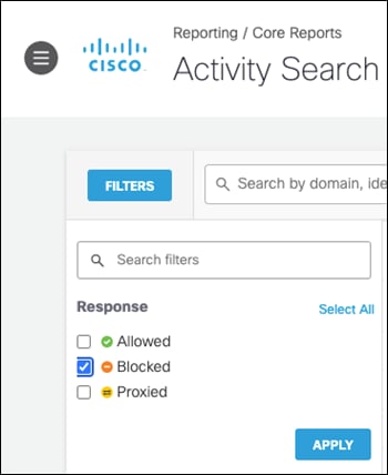
Step 5. Verify the entry for Facebook has been logged.

Validation Test #3 – Umbrella Firewall policies are being triggered
Step 1. Download and install the BitTorrent application onto the client machine.
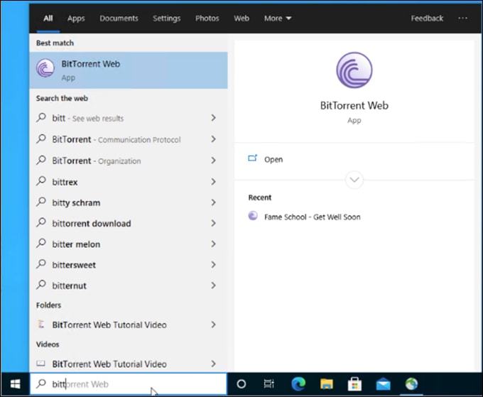
Step 1. In any browser, navigate to https://now.bt.co.

Step 2. Download any file from the site.

Step 3. Open the file on the client machine. This will attempt to download the file from a P2P network.
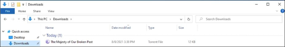
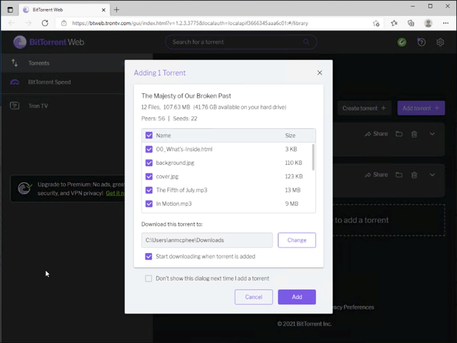
Note: There is a chance that some files will make it into the network. In this case, Cisco Secure Endpoint will analyze any malicious files and block accordingly. Nevertheless, it was validated that no data was seeded to other clients, meaning 100% of outbound activity was blocked by Umbrella policy.
Step 4. In the Umbrella Dashboard, navigate to Reporting > Core Reports > Activity Search.
Step 5. In the Filters tab, check the Blocked box under Response and click Apply.
Step 6. Verify the P2P activity has been logged.
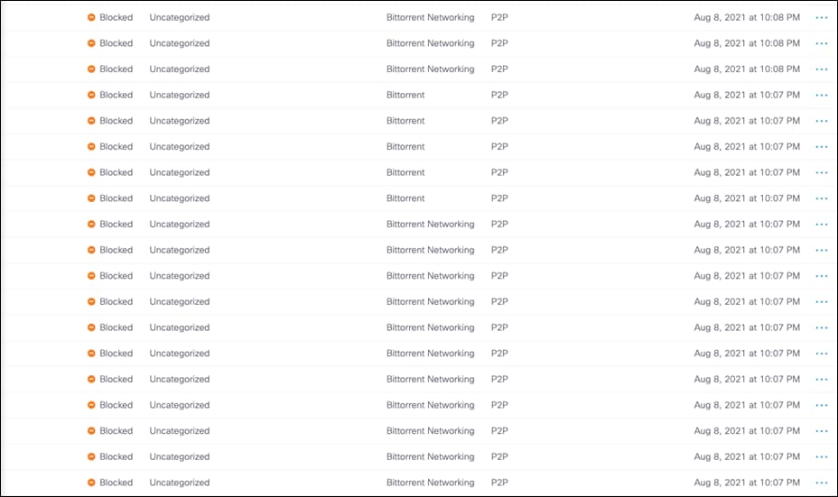
Validation Test #4 – Umbrella DLP Policies have been triggered
Step 1. In any browser, navigate to any cloud storage site. This design guide will use Box.
Step 2. Upload a file containing random US credit card numbers. Example below.
6011 1834 5527 3209
Discover
6011 2150 2716 5024
Discover
4328 1373 5449 1554
Visa
5430 3563 9033 0772
MasterCard
6011 0430 8746 4644
Discover
6011 6766 2381 3665
Discover
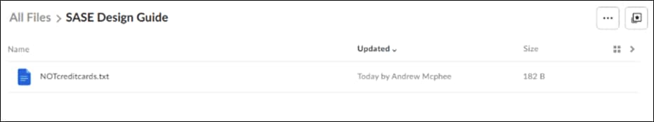
Step 3. In the Umbrella Dashboard, navigate to Reporting > Additional Reports > Data Loss Prevention.
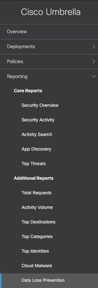
Step 4. An event will be created for the file that was uploaded.
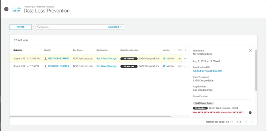
Validation Test #5 – Umbrella Remote Browser Isolation
Step 1. In any browser, navigate to https://dropbox.com (the site chosen for our DLP policy).

Step 2. Download any file.
Step 3. The file will download and open in a remote browser, which can be confirmed by looking at the URL of the opened file.

Step 4. In the Umbrella Dashboard, navigate to Reporting > Core Reports > Activity Search.
Step 5. In the Filters tab, check the Isolated box under Isolate and click Apply.
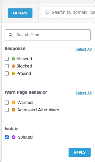
Step 6. Verify that the session to Dropbox has been logged.

Validation Test #6 – Intrusion Prevention System
Step 1. Open a command prompt and type the following:
curl http://3.25.228.160/test.emf
Step 2. In the Cisco Umbrella dashboard, navigate to Reporting > Core Reports > Activity Search.
Step 3. Under IPS Signature filters, click Select All and then Apply.

Step 4. The activity log should show an IPS log that triggered based on a Microsoft emf file download request.

Validation Test #7 – Duo SSO for SaaS Applications
Step 1. In any browser, navigate to https://login.microsoftonline.com and sign into your Microsoft 365 domain.

Step 2. Verify that the sign-on process is routed to Cisco Duo SSO.

Step 3. Verify your identity with Cisco Duo MFA.

Step 4. In the Duo Dashboard, navigate to Reports > Authentication Log and verify an SSO event was logged.

Validation Test #8 – ThousandEyes Observability matches desired outcomes
Step 1. In the ThousandEyes dashboard, navigate to Dashboards.
Step 2. Under Tests, verify that the blocked websites (Facebook and TikTok) are running at 0% availability.
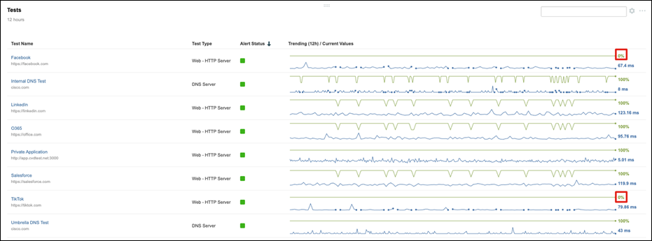
Step 3. Under Tests, verify that LinkedIn is running closer to 100% availability.
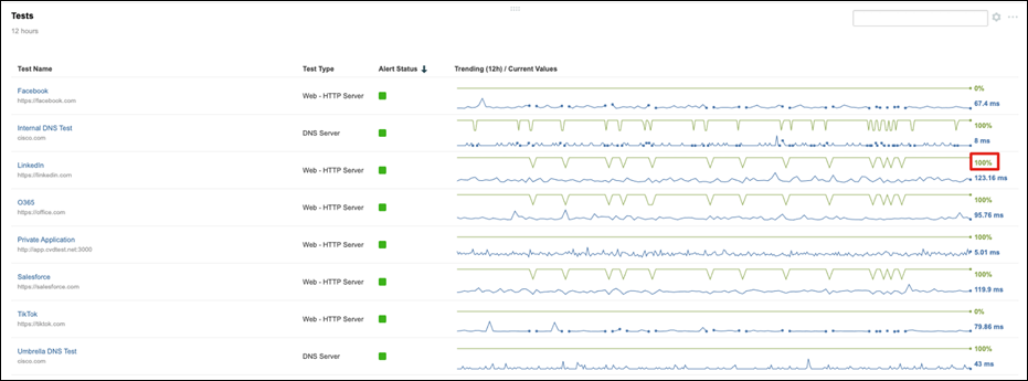
Step 4. Under Tests, click Salesforce.
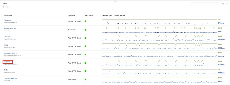
Step 5. Under Views > Network click on Path Visualization.
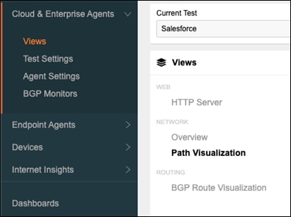
Step 6. To check the latency through Umbrella, highlight the branch node. In this case, latency is 7ms.
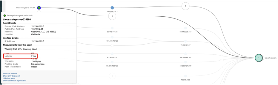
Step 7. Hover over a cloud agent node and check the latency. A Cloud agent in the AT&T network has a 180ms latency to Salesforce.
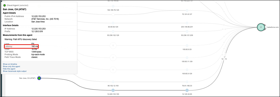
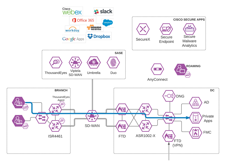
Branch User to Private Application in Data Center
Validation Test #1 – Private domain access does not flow through Umbrella
Step 1. Using any browser while on a client in the branch network, navigate to a private application located in the Data Center. Internal traffic should be routed in the SD-WAN network, and not through Umbrella, where the internal domain would not be resolvable.

Note: This Design Guide is limited in scope, and therefore does not include security that would exist within the Data Center. An assumption has been made that the appropriate protections will be in place within the Data Center to protect private application access from users in the branch network.
Validation Test #2 – ThousandEyes Observability matches desired outcomes
Step 1. In the ThousandEyes dashboard, navigate to Dashboards.
Step 2. Under Tests, verify that the private application(s) is running near 100% availability.
![]()
Appendix A – Install the Cisco Umbrella Root Certificate
Umbrella’s Block Page and Block Page Bypass features present an SSL certificate to browsers that make connections to HTTPS sites. This SSL certificate matches the requested site but will be signed by the Cisco Umbrella certificate authority (CA). If the CA is not trusted by your browser, an error page may be displayed. Typical errors include “The security certificate presented by this website was not issued by a trusted certificate authority” (Internet Explorer), “The site’s security certificate is not trusted!” (Google Chrome) or “This Connection is Untrusted” (Mozilla Firefox). Although the error page is expected, the message displayed can be confusing and you may wish to prevent it from appearing. The example below shows how to install the root certificate to an Active Directory Network. For more examples see Install Cisco Umbrella Root Certificate.
Step 1. In the Umbrella Dashboard, navigate to Deployments > Configuration > Root Certificate and download the Cisco Root Certificate Authority.
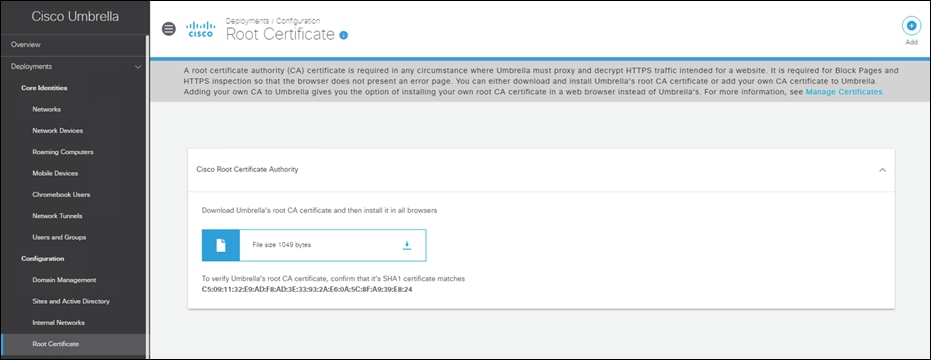
Step 2. In the Active Directory server for your network, open Group Policy Management.
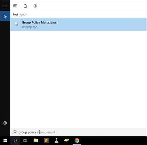
Step 3. Right-click your domain root Organizational Unit (OU), which is displayed as your domain name, and select Create a GPO in this domain, and Link it here from the context menu.
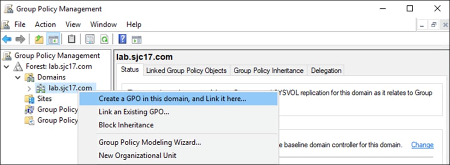
Step 4. In the Name field of the New GPO dialog box, enter a meaningful name for the policy object.
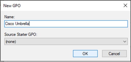
Step 5. Right-click on the new Group Policy Object that was created in the previous step and click Edit.
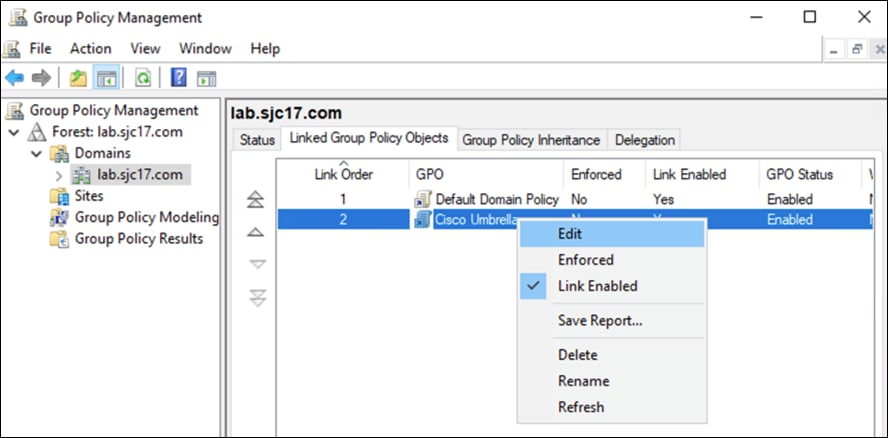
Step 6. Navigate to Computer Configuration > Policies > Windows Settings > Security Settings > Public Key Policies and right-click Trusted Root Certification Authorities. Click Import.
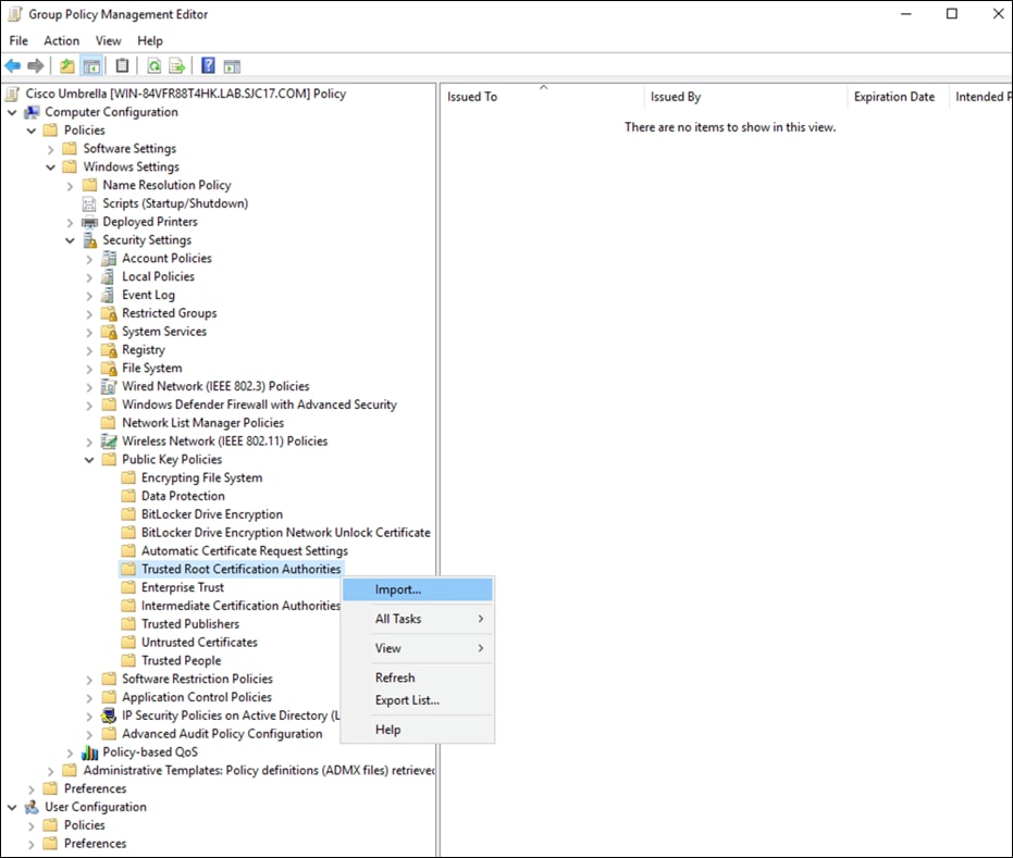
Step 7. In the Certificate Import Wizard click Browse and add the certificate downloaded from Umbrella in step 1. Click Next.
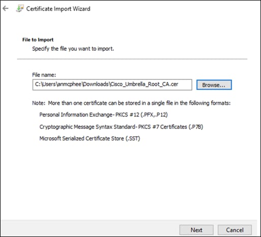
Step 8. Accept all default options until the final windows and click Finish.
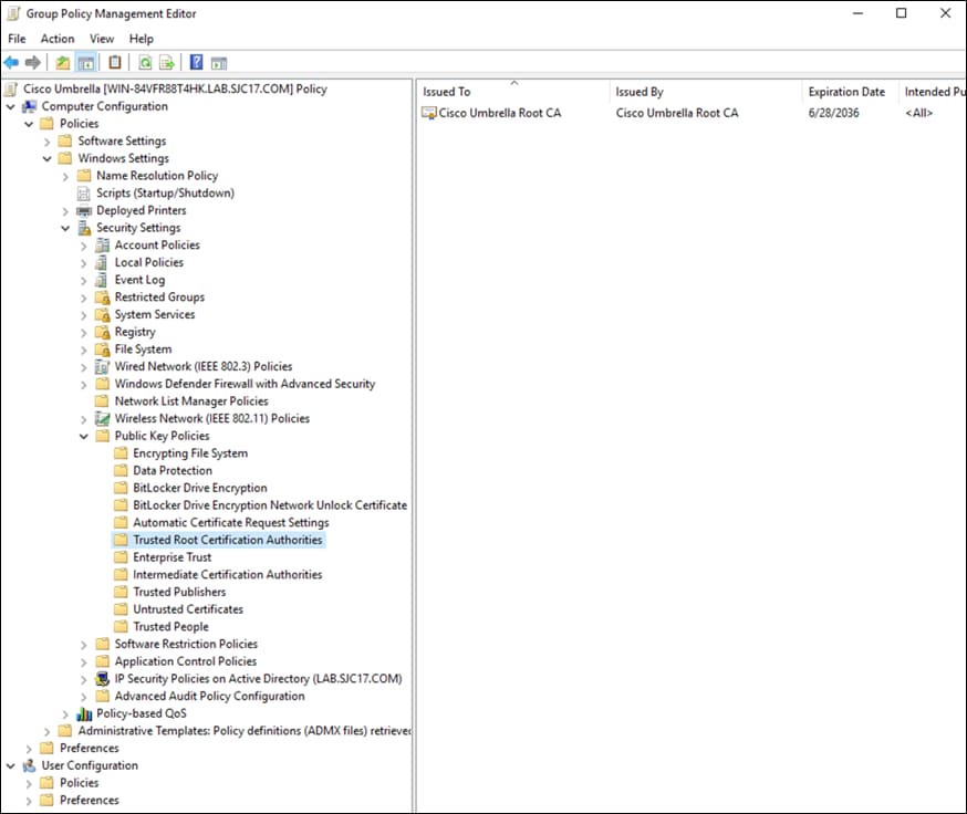
Appendix B – Umbrella Web Selective Decryption List
For this design guide, Office 365 will be excluded from decryption through Umbrella. There are several known compatibility issues with Office 365 and web proxies and exempting Office 365 traffic authentication. Decryption can help with some of these issues.
Step 1. In the Umbrella Dashboard, navigate to Policies > Policy Components > Selective Decryption Lists.
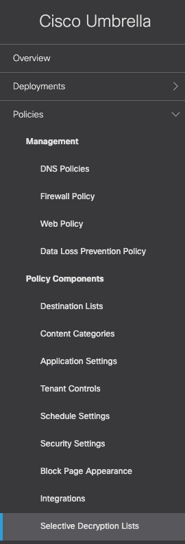
Step 2. Click Add.

Step 3. Give a meaningful List Name to the decryption list.
Step 4. Beside Applications Selected, click Add.
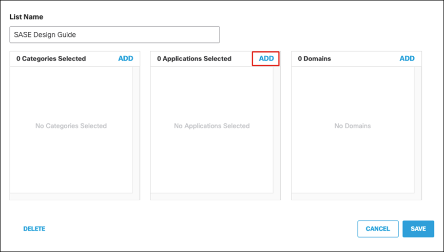
Step 5. Search for Office 365 and click the checkbox to enable. Click Close.
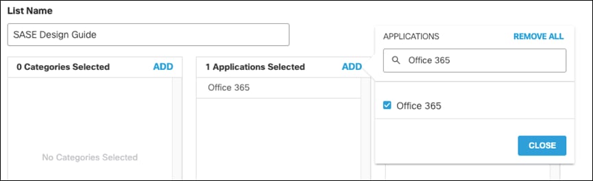
Step 6. Click Save.
To add more content that should bypass decryption, continue to add to this list using either a content category, application, or domain.
Appendix C – Using FTP to transfer files to IOS-XE
Step 1. Connect to the IOS-XE router via console.
Step 2. Enter configuration mode by typing the command config-t.
Step 3. Enter the following commands to assign a private IP to an interface on the router and choose that interface as the source for FTP traffic:
interface GigabitEthernet0/0/1
ip address 192.168.1.1 255.255.255.0
no shut
exit
ip ftp source-interface GigabitEthernet0/0/1
Step 4. Connect a PC running an FTP server to port GigabitEthernet0/0/1 and assign it an IP in the 192.168.1.0/24 range.
Step 5. Load the necessary file on the FTP server.
Step 6. On the IOS-XE device, type the following command to copy the file to bootflash
copy ftp://user:pass@192.168.1.2/<filename> bootflash:
| Acronym |
Definition |
| AMP |
Advanced Malware Protection |
| ASA |
Adaptive Security Appliance |
| ASDM |
Adaptive Security Device Manager |
| CA |
Certificate Authority |
| CASB |
Cloud Access Security Broker |
| CDFW |
Cloud Delivered Firewall |
| DIA |
Direct Internet Access |
| DLP |
Data Loss Prevention |
| DNG |
Duo Network Gateway |
| DNS |
Domain Name System |
| FMC |
Firewall Management Center |
| FTD |
Firepower Threat Defense |
| IoC |
Indicator of Compromise |
| IPS |
Intrusion Prevention System |
| MFA |
Multi-Factor Authentication |
| MPLS |
Multiprotocol Label Switching |
| MSP |
Managed Service Provider |
| OU |
Organizational Unit |
| P2P |
Peer-to-Peer |
| PHI |
Personal Health Information |
| PII |
Personally Identifiable Information |
| RBI |
Remote Browser Isolation |
| SaaS |
Software as a Service |
| SASE |
Secure Access Service Edge |
| SD-WAN |
Software Defined Wide Area Network |
| SSL |
Secure Sockets Layer |
| SSO |
Single Sign-On |
| SWG |
Secure Web Gateway |
| VPN |
Virtual Private Network |
● Cisco Breach Defense Design Guide
● Cisco SD-WAN powered by Viptela
● Cisco SD-WAN Deployment Guide
● Cisco SD-WAN Controller Setup Guide (On-Prem, Non-Cloud-Managed)
● Cisco SD-WAN How to Onboard a Remote Router into an Existing SD-WAN Fabric
● Cisco ThousandEyes User Documentation
● Cisco Umbrella User Documentation
If you have feedback on this design guide or any of the Cisco Security design guides, please send an email to ask-security-cvd@cisco.com.