Test Modules That Accelerate Technology Adoption
Available Languages
Bias-Free Language
The documentation set for this product strives to use bias-free language. For the purposes of this documentation set, bias-free is defined as language that does not imply discrimination based on age, disability, gender, racial identity, ethnic identity, sexual orientation, socioeconomic status, and intersectionality. Exceptions may be present in the documentation due to language that is hardcoded in the user interfaces of the product software, language used based on RFP documentation, or language that is used by a referenced third-party product. Learn more about how Cisco is using Inclusive Language.
Communications networks have evolved to become the critical foundation of digital business around the globe. Changes to communications network infrastructure can have a very significant impact on the systems that the networks support. Consequently, validation of changes to communications network infrastructure is of major importance.
The close coupling between network infrastructure resiliency, and business continuity and resiliency has led to the emergence of new operational practices. Development of automation and orchestration systems, to drive repeatable and accurate execution of non-disruptive changes to network infrastructure, is becoming a key aspect of these operational practices.
The introduction of software development practices into the domain of communications network has been termed NetDevOps. As with DevOps practices in the wider software development community in general, validation testing has to be incorporated into the NetDevOps lifecycle to ensure that implementation and operational changes will not impact business continuity.
NetDevOps is a focus for our customers as it enables agility and so helps maximize the value of their investments in the communications network technology, they need to run their business. Such agility is central to the CX vision as it allows us to help our customers grow their business on a stable and reliable platform.
Integrating testing and validation into NetDevOps supports adoption and helps increase the business agility that our technology platforms support.
Complexity and cost of testing
Testing and validating of network and how these operate to specific parameters required by the business, have mostly been an exercise available only to those that have the financial capacity to source an environment for testing or those that pay for third party services to complete the task. As the adoption of automation has accelerated in IT operations environments, so has the inclusion of testing integrated into the deployment and daily operations.
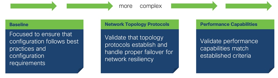
Baseline testing plays a key role in validation efforts and is the most common type of testing conducted. This testing effort is to ensure that configuration adheres to specific requirements. Common tools that are used for configurations during a deployment, are orchestration and automation tools like Ansible. These take the task of accelerating and validating the configuration while removing the context of human error.
Network topology protocols establish how devices connect to each other to extend the network topology mesh. Examples of these protocols are OSPF, EIGRP, ISIS that can be used by other layers like BGP/EVPN. Validation of these protocols’ configuration and operational state across different network elements, is critical for proper functionality.
For Network topology protocols there is a need to consider that both control plane configuration and data plane behavior have to be independently validated. While validation of the control plane can be accomplished with virtualized network elements, this level of validation is not sufficient for physical network devices as the underlying hardware elements (ASICS & FPGA) that are programmed from the control plane have to be tested.
When considering the dimension of testing network performance, a significant aspect of complexity is introduced by test tools focused on packet generation. The complexity of including such tools can stretch from generate packet counts to the more complex protocol emulation for scale of routing table and hardware programming. More complex tools can also achieve the inclusion of testing elements for application behaviors over network-like emulation of client/server communications of protocols such as Web applications, Audio and Video.
As with any technical effort, specialized knowledge is critical to provide an accelerated pace of adoption. Engineers with the knowledge and capability to perform validation testing are different than engineers capable of creating design implementations. In every technology company, a small group of specialists oversee defining, coding and performing the test implementation that is related to a product. These tests architects usually focus purely on functional testing of devices based on the protocols they are releasing with the product. This testing can also be created by the engineer that is writing the code and implemented by the testing team.
With test modules the implementation takes a different approach as the focus is on continuous testing capabilities post-installation of said network device. When implementing test modules, the capability that is being tested is focused on how to validate the function in relation to how the implementation is to be completed. We know that the engineering teams have done the first round of testing that is specific feature and functional testing. With test modules, we can provide the capability for engineers that are designing and implementing a network solution to easily “consume” the modules capability to validate how the implementation is configured or performing.
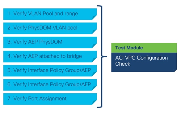
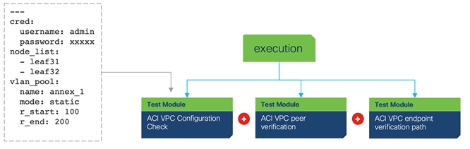
To properly align the requirements to the network function, the test modules would be aligned to specific technology elements of the network. Using an example of verifying that an ACI VPC Configuration is properly configured, a module would require specific verification for ACI objects that compromise its configuration such as Physdom, AEP and other elements to be properly setup.
The module capability that was written by an expert testing engineer, would ensure that the validation of these network elements is robust. This avoids the situation of testing logic that doesn’t meet the highest standards which can lead to false positives of what is being validated. Engineers that are not adapted to network testing, don’t have the knowledge of determining the proper instrumentation and testing tools that could perform the task to the highest standards.
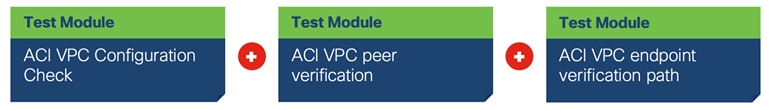
The modules can also be combined in a way to create a test validation chain. In the case of the Cisco ACI VPC configuration checks, to make sure that the VPC is operational, we must focus on various elements of the object structure for ACI. Starting with verifying that each ACI object is properly related to the other objects, then verifying that the peering status is in the correct state and then finally doing some verification of endpoint learning.
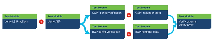
This module structure allows the creation of a validation chain that can adapt to specific network requirements. For example, when creating such validation elements, the requirements might be unique for each element. A network under test might have a requirement to validate that the ACI L3out element is configured for BGP instead of using OSPF. Specific modules can be combined to verify each functional element.
This capability makes it possible to provide granular selection of testing elements from different execution points which could be a testing script or a pipeline execution. This also allows for test case logic to reside at a higher “architectural” level providing the definition of the logic to execute be adapted to requirements of each particular deployment.
It becomes imperative that the modules require little to no code changes to be implemented in different scenarios. This is critical and divergent from some methodologies where specific parameters end up hard coded into the code making it very complex to be controls via parameters.
To address this, each module contains a data structure file that defines the required values that would need to be modified for test execution. To simplify how these different parameters are input into the modules, YAML should be used to provide an easy-to-read structure to the operator.
Having the ability to include these as part of a GIT repository moves the needle closer to collaboration amongst teams and aligning to Infrastructure as Code. Since the data structure is independent of the modules, the capability would exist to separate the module execution data structure from the provided module that could be executed directly from container type execution that better aligns with CI/CD pipeline executions.
With the focus on modularity explained, the next step is to utilize a framework that is capable of execution. To simplify this capability, we will focus on the utilization of the Robot Framework. This open-source framework gives us the capabilities to create an abstraction layer to the module code. This is critical as we talk about the capability to define test case logic outside of the code itself.
The test modules need to be defined in a way that each module solves a specific test function element. It is important for each module to implement code logic that addresses solely a specific modularized logic and not be an overall test case. Let’s observe the following example:
| Test Device #1 |
Test Device #2 |
| interface Ethernet1/1 description Link to Device2 ip flow monitor svs-prt-pi-1 input ip flow monitor svs-prt-pi-1 output ip address 10.0.1.2/30 ipv6 address 2001:420:27c2:5::2/64 ip ospf network point-to-point no ip ospf passive-interface ip router ospf SVS-RTP-Lab area 0.0.0.0 ospfv3 network point-to-point no ospfv3 passive-interface ipv6 router ospfv3 SVS-RTP-Lab area 0.0.0.0 ip pim sparse-mode no shutdown |
interface TenGigabitEthernet4/5 description Link to Device1 ip address 10.0.1.1 255.255.255.252 ip pim sparse-mode ip ospf network point-to-point ipv6 address 2001:420:27C2:5::1/64 ipv6 enable ipv6 ospf 109 area 0 ipv6 ospf network point-to-point |
For this setup there is a need for verification of setup state between these two devices. If the engineer writes in the test case logic that it needs to specifically find and match these elements, then the code would become very difficult to be modified and utilized on different setups.
Yet if the code was written to verify each element that is required, then a higher-level logic-like Robot could be utilized to define the logic required to complete the task. As an example of this, the following Robot code would take an input to check a specific device that a specific OSPF neighbor association is established and in FULL state.
Robot Logic using modules:
5. Checking OSPF Adjacency full
use device "${DUT1}"
run parsed json "sh ip ospf neighbors"
${status}= get parsed "state" where "addr" is "${dut2_int_1_ip}"
Run Keyword If '${status}' != 'FULL' FAIL OSPF Nbr state is ${status} not FULL
... ELSE Log ++PASS++ OSPF Nbr state is FULL
Log OSPF Nbr Validation Success on Dut
A module would then encompass various of these elements to verify that the OSPF neighbor is properly configured. In the case of OSPF, just utilizing this single step would be overly simplistic and can lead to a failure of verification that the network is operating correctly from a neighbor adjacency. A more robust test of this would be to also include verification that the element is working on the proper interface as can be seen in this list:
1. Verify specific interface is up/up
2. Verify proper L1 adjacency to match topology requirement
3. Verify proper OSPF parameters configured on interface
4. Verify OSPF neighbor adjacency is full (if required also verify HW forwarding entry)
These four elements could be combined to create a single module that would contain the proper elements of testing determined by experts and be easy to consume.
Combining the elements towards automated pipelines
In today’s world, the inclusion of testing aligned with continuous delivery is paramount to proper operations. DevOps (Developer Operations) is a methodology used by software code development teams to automate the process of building applications and deploying them. These are usually completely automated pipelines that are triggered at events in the code.
For the networking world there is been an interest in utilizing CI/CD process to make it possible to automate network changes. These changes might include software and configuration changes, making it possible for the network operator to easily modify the network. One element is used to verify that such a change will not cause problems to the present configuration. In large networks the inclusion of a lab test topology or the use of providers of testing services like Cisco, allows for verification before deployment directly tied to topologies and configuration specific to the network operator. This additional level of verification might even include multiple vendors, applications, and other network elements to ensure that the changes will not disrupt the network.
The test modules align to this vision. Providing a quick and easy way to define how to create tests with the automated modules and providing the different paths on how to utilize these from the same pipeline. Observing the diagram Figure 5 CI/CD pipelines and test modules you can observe that the inclusion of these modules in a pipeline can be achieved in various ways.
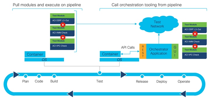
The first way to include these modules involves pulling the code directly into execution mechanism (e.g., container) and calling the modules execution with the parameter data included via YAML. This can be accomplished by pulling the data structures that are needed for the execution and then executing containers from a container repository.
The second option allows for the utilization of an orchestration facility that contains API’s that can be called to execute. The second option is popular as it allows for easier definition of what and how to test by defining directly in a GUI and then providing the ability to execute that defined logic directly from an API.
In conclusion, networks currently in operations are sometimes tested with simple pings. The complexity of the network and what is carried on it requires a more robust approach. Programmatic automation has provided the capability to execute these in a consistent, repeatable fashion, allowing for integration in business processes. Yet, the best method to execute such testing requires that the authors not only understand programmatic automation; but also understand what the best way for such network technology is to be validated. Using testing modules allow for us to create prescriptive validation that is easily shared and consumed, allowing for quick testing of network devices and protocols to accelerate the adoption of change in any network.
| Contributor |
Title |
| Rafael Muller |
Principal Engineer, CX |
| Reviewer |
Title |
| Nathan John Sowatskey |
Principal Engineer |
| Jacob Adelman |
Technical Lead – Software Consulting Engineer |
| Oliver Boehmer |
Principal Architect |
| Richard Froom |
Director, Customer Delivery |