802.1q Trunking on the CSS 11x00 Configuration Example
Available Languages
Contents
Introduction
This document provides a sample configuration for 802.1q trunking on the Content Services Switch (CSS) 11x00 series switch.
Before You Begin
Conventions
For more information on document conventions, see the Cisco Technical Tips Conventions.
Prerequisites
There are no specific prerequisites for this document.
Components Used
This configuration was developed and tested using the software and hardware versions below.
-
CSS 11800 and CSS 11150 running 4.10 in a lab environment with cleared configurations
The information presented in this document was created from devices in a specific lab environment. All of the devices used in this document started with a cleared (default) configuration. If you are working in a live network, ensure that you understand the potential impact of any command before using it.
Background Theory
With WebNS release 4.10, the CSS 11000 supports IEEE Standard 802.1Q VLAN trunking on Gigabit Ethernet (GE) ports.
802.1Q support is important for web hosters and other service providers who have multiple customers sharing a single device. The web hoster can now isolate their customer's on individual traffic through VLANs eliminating the need for each customer to be assigned a single port. As web traffic comes in from the Internet, the router isolates the traffic into separate VLANs based on destination (for example, IP, port, and so on), and trunks them together within one Gigabit port. This trunk is then passed to the CSS11x00 for load-balancing decisions. The CSS sends the trunk to a Layer 2 (L2) device to be passed to the server farm. From the router to the servers, the VLANs's traffic is isolated. Only two Gigabit ports were used on the CSS 11x00.
Tests have shown that the addition of 802.1Q has minimal performance impact on the CSS 11x00 switch.
CSS 11x00 support of 802.1Q also improves its interoperability with other Cisco devices, such as the Catalyst 6500. These two devices are the foundation of Cisco's Content Switching Solution, Tundra, and are an integral part of our recommended content networking solution.
Note: Prior to 802.1Q support, in order to achieve isolation between VLANs, a L2 device could be placed between the router and the CSS. This device would take the trunk, break out the individual VLANs, and pass traffic through multiple connections to the CSS. Additional connections could pass the traffic to the server farms. Traffic could be isolated however at a higher cost and port usage.
Web Hoster Application
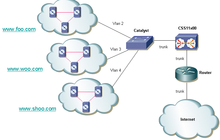
A web hoster has a single CSS 11x00 (and a redundant CSS for high availability). The web hoster needs to provide support for 100 customers and would like to minimize port usage on the CSS 11x00. This allows for maximization of return on the CSS ports. The following diagram shows one possible configuration that will allow this to be accomplished:

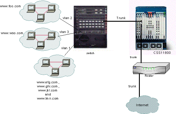
For each customer, the option can be given to isolate his or her traffic. This means that they will be given a unique VLAN. In the example above, www.foo.com can be isolated from www.woo.com. A new Gigabit port would be required for every 32 customers. It is possible to mix VLANs with 802.1Q tagging enabled and also offer an untagged VLAN. This would allow the web hoster to offer isolation and non -isolated VLANs to the customer. The following diagram shows how this network would look:

In this example, domains efg, ghi, jkl, and lmn would be sharing a VLAN. This means that all multicast traffic for any of them would be sent to all of them. Domains foo and woo would only receive multicast traffic destined for their domain.
What is 802.1Q?
The term VLAN refers to the ability to "virtualize" a Local Area Network (LAN) using a switched architecture. The benefit of using VLANs is that each user device can be connected to any VLAN. Rather than be defined on a physical or geographical basis, VLANs can be defined on a logical or organizational basis where the network can be configured via software instead of by manually re-plugging wires. Administrators can implement VLANs and save ports by implementing trunking. In Cisco's terminology, a trunk is a point-to-point link carrying several VLANs. The goal of a trunk is to save ports when creating a link between two devices implementing VLANs, typically two switches. In the diagram below, you can see two VLANs that you want available on two switches, Sa and Sb. The first method to implement is easy. This method requires you to create two physical links between the devices, each one carrying the traffic for a VLAN.

Of course, this solution does not scale. If you wanted to add a third VLAN, you would need to sacrifice two additional ports. This design is also not beneficial in terms of load sharing. The traffic on some VLANs may not justify a dedicated link. A trunk will bundle virtual links over one physical link, as shown in the following diagram:

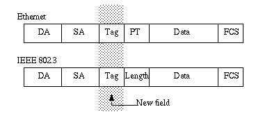
In this diagram, the unique physical link between the two switches is able to carry traffic for whatever VLAN. In order to achieve this, each frame sent on the link is tagged by Sa so that Sb knows to which VLAN it belongs. 802.1Q uses an internal tagging mechanism. Internal means that a tag is inserted within the frame, as shown below.

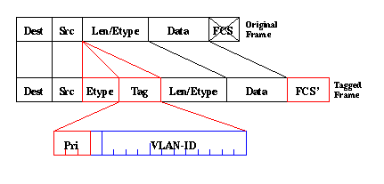
Note that on a 802.1Q trunk, one VLAN may not be tagged. This untagged VLAN is referred to as the default VLAN. This way, you can deduce to which VLAN a frame belongs to that is received without a tag. The tagging mechanism implies a modification of the frame. The trunking device inserts a 4-byte tag and recomputes the Frame Check Sequence (FCS). See Bridging Between IEEE 802.1Q VLANs for more information on tagging schemes.

802.1Q standard is more than just a tagging mechanism. It also defines a unique spanning-tree, running on the default VLAN, for all of the VLANs in the network.
Note: The pri field is not currently supported by the CSS 11000.
Configure
The configuration of the CSS 11x00 with 802.1Q requires WebNS 4.10 code or greater. This feature is supported on the Gigabit ports only (CSS11000 only). The maximum number of 802.1Q trunk ports is equal to the number of Gigabit ports on the switch. On the CSS 11150 , the maximum number of Gigabit ports is two (on the CSS 11050 the maximum is one). On the CSS 11800, the maximum number of Gigabit ports is 32, and the maximum number of VLANs supported across all ports is 128 with no more than 32 on a single Gigabit port.
This list defines the maximum number of VLANs supported by the specific CSS models:
-
CSS 11501 and CSS 11503—a maximum of 256 VLANs
-
CSS 11506—a maximum of 512 VLANs
-
CSS 11050 and CSS 11150—a maximum of 16 VLANs
-
CSS 11800—a maximum of 128 VLANs
VLAN parameters within the CLI have been modified to allow for the tagging functionality. The definitions have remained the same as previous releases. The following section describes how the CLI parameters are entered. For definitions, see the CLI Command Reference Guide.
Configurations
This document uses these configurations:
-
Enabling/Disabling Trunking
-
Configuring the VLANs associated with the trunk
-
Configuring the bridge priority for the interface/VLAN pair
-
Configuring the bridge state
-
Configuring bridge pathcost
-
Default-vlan command
-
ARP command
| Enabling/Disabling Trunking |
|---|
To enable trunking: CS800# config CS800(config)# interface 1/1 CS800(config-if[1/1])# trunkTo disable trunking: CS800(config-trunkif[1/1])# no trunk Disable trunking, [y/n]:y CS800(config-if[1/1])# exit |
| Configuring the VLANs associated with the trunk |
|---|
To create a VLAN on a particular trunk, you must first attach to the interface and then enter in the VLAN that you want to associate with it. The following example is associating VLANs 2 and 3 with interface 1: CS800# config CS800(config)# interface 1/1 CS800(config-if[1/1])# trunk CS800(config-trunkif[1/1])# vlan 2 Create VLAN <2>, [y/n]:y CS800(config-trunkif[1/1-2])# exit CS800(config-trunkif[1/1])# vlan 3 Create VLAN <3>, [y/n]:y CS800(config-trunkif[1/1-3])# exit |
| Configuring the bridge priority for the interface/VLAN pair |
|---|
The following command changes the priority for the specified interface/VLAN pair. The default is 128. In the following example, the bridge priority is changed from 128 to 50: CS800# config CS800(config)# interface 1/1 CS800(config-if[1/1])# trunk CS800(config-trunkif[1/1])# vlan 1 Create VLAN <1>, [y/n]:y CS800(config-trunkif[1/1-1])# bridge priority 50 |
| Configuring the bridge state |
|---|
The following command, bridge state, changes the spanning-tree priority state on a given interface/VLAN pair. By default, the state is enabled. CS800# config CS800(config)# interface 1/1 CS800(config-if[1/1])# trunk CS800(config-trunkif[1/1])# vlan 1 Create VLAN <1>, [y/n]:y CS800(config-trunkif[1/1-1])# bridge state disabled |
| Configuring bridge pathcost |
|---|
The following command, bridge pathcost, will change the spanning-tree port pathcost on a given interface/VLAN pair. The cost can be any integer between 1 and 65535. The default is 0. In the following example, the pathcost is changed from 0 to 2: CS800# config CS800(config)# interface 1/1 CS800(config-if[1/1])# trunk CS800(config-trunkif[1/1])# vlan 1 Create VLAN <1>, [y/n]:y CS800(config-trunkif[1/1-1])# bridge pathcost 2To return the bridge pathcost back to 0, issue no bridge pathcost command. |
| Default-vlan command |
|---|
This command has two purposes. It specifies the default VLAN to use for frames that arrive untagged on this interface. It also specifies that frames transmitted out this VLAN will be untagged. The default VLAN must be explicitly set if the user wishes untagged frames to be processed, otherwise they will be discarded. If the user wishes to discard untagged frames, the default-vlan command should be omitted. This command must not be defined in any other VLAN. If the user attempts to define more than one VLAN with the default-vlan command, the command returns an error. To change the default VLAN, the user must first issue no default-vlan on the old VLAN, and default-vlan on the new VLAN. CS800# config CS800(config)# interface 1/1 CS800(config-if[1/1])# trunk CS800(config-trunkif[1/1])# vlan 1 Create VLAN <1>, [y/n]:y CS800(config-trunkif[1/1-1])# default-vlan CS800# config CS800(config)# interface 1/1 CS800(config-if[1/1])# trunk CS800(config-trunkif[1/1])# vlan 1 Create VLAN <1>, [y/n]:y CS800(config-trunkif[1/1-1])# default-vlan CS800(config-trunkif[1/1-1])# vlan 2 Create VLAN <2>, [y/n]:y CS800(config-trunkif[1/1-2])# default-vlan %% Must use 'no default-vlan' first to clear old default VLAN CS800(config-trunkif[1/1-2])# vlan 1 CS800(config-trunkif[1/1-1])# no default-vlan CS800(config-trunkif[1/1-1])# vlan 2 CS800(config-trunkif[1/1-2])# default-vlan |
| ARP Command |
|---|
The ARP command can be used to determine the hardware address that is associated with the IP address. Modifications have been added to allow for the additional VLAN arguments. On trunking interfaces, the ARP command is as follows:
Arp ip address mac address interface vlan
On non-trunking interfaces, the arp command is as follows:
Arp ip address mac address interface
|
Note: If a user enters the vlan argument on a non-trunking interface, or does not enter the vlan argument on a trunking interface, the host entry will not appear in the IP routing table.
Viewing Screen Changes
This section provides information on how to view the running-config changes on the CSS 1115x.
All interfaces have a consistent prefix format. This is the case for the CS800. The slot/port format will not change. The CSS 11150, however, currently displays ethernet-X in some places, and simply X (a number from 1 to 16) in others. They have a common format, eX. For example, e1, e2, and e16. This format is supported when entering commands. Also on the command side, the ethernet-X format continues to be supported for backwards-compatibility with older startup-configs and scripts.
Note: Only the Gigabit ports can be configured as VLAN trunk ports.
CS100# sho running-config
configure


!*************************** GLOBAL ***************************
  no console authentication

!************************* INTERFACE *************************
interface e1
  bridge vlan 2

interface e2
  bridge vlan 3
Below is another example of the show running-config with new 802.1Q configurations.
configure


!************************* INTERFACE *************************
interface 1/1
  trunk

  vlan 1
    default-vlan
    bridge pathcost 11
    bridge priority 50
    bridge state disable

  vlan 2
    bridge pathcost 50
    bridge priority 1

interface 1/2
  bridge priority 20
Verify
This section provides information you can use to confirm your configuration is working properly.
Certain show commands are supported by the Output Interpreter Tool (registered customers only) , which allows you to view an analysis of show command output.
-
show bridge status VLAN - For interfaces that have trunking enabled, append -X (where X is the VLAN number) to the prefix. For example, 1/3-4 means slot 1, port 3, VLAN 4. For a GE NIC port on the CS100, e13-22 means Ethernet port 13, VLAN 22. If trunking is not enabled (or not supported as on 10/100 Mbps ports), there is nothing appended to the prefix.
CSS 11150
CSS150# show bridge status
VLAN1:   Root Max Age:  6  Root Hello Time:  1  Root Fwd Delay:  4
Designated Root: 80-00-00-10-58-ca-fe-bb
Bridge ID:       80-00-00-10-58-ca-fe-bb
                                                              Root Port Desg
Port    State Designated Bridge       Designated Root         Cost Cost Port
----    ----- ----------------------- ----------------------- ---- ---- ----
e1        Fwd 80-00-00-10-58-ca-fe-bb 80-00-00-10-58-ca-fe-bb    0   10 8001
e2        Fwd 80-00-00-10-58-ca-fe-bb 80-00-00-10-58-ca-fe-bb    0   10 8001
e13       Fwd 80-00-00-10-58-ca-fe-bb 80-00-00-10-58-ca-fe-bb    0   10 8001
e14-1     Fwd 80-00-00-10-58-ca-fe-bb 80-00-00-10-58-ca-fe-bb    0   10 8001
e14-3     Fwd 80-00-00-10-58-ca-fe-bb 80-00-00-10-58-ca-fe-bb    0   10 8001
e14-4     Fwd 80-00-00-10-58-ca-fe-bb 80-00-00-10-58-ca-fe-bb    0   10 8001
CSS 11800
CSS11800# show bridge status
VLAN1 STP State:        Enabled
VLAN1:   Root Max Age:  6  Root Hello Time:  1  Root Fwd Delay:  4
Designated Root: 80-00-00-10-58-57-ec-08
Bridge ID:       80-00-00-10-58-57-ec-08
                                                                 Root Port Desg
Port       State    Designated Bridge       Designated Root      Cost Cost Port
----       ----- ----------------------- ----------------------- ---- ---- ----

VLAN2 STP State:        Enabled

VLAN2:   Root Max Age:  6  Root Hello Time:  1  Root Fwd Delay:  4
Designated Root: 80-00-00-10-58-57-ec-09
Bridge ID:       80-00-00-10-58-57-ec-09
                                                                 Root Port Desg
Port       State    Designated Bridge       Designated Root      Cost Cost Port
----       ----- ----------------------- ----------------------- ---- ---- ----
 1/2        Fwd  80-00-00-10-58-57-ec-09 80-00-00-10-58-57-ec-09    0   19 8002
 2/1-2      Fwd  80-00-00-10-58-57-ec-09 80-00-00-10-58-57-ec-09    0    4 8009
 2/2-2      Fwd  80-00-00-10-58-57-ec-09 80-00-00-10-58-57-ec-09    0    4 800a
To display one VLAN at a time, enter the show bridge status VLAN# command, where # is the number of the VLAN. For example:
CSS11800(debug)# show bridge status VLAN2
VLAN2 STP State:        Enabled
VLAN2:   Root Max Age:  6  Root Hello Time:  1  Root Fwd Delay:  4
Designated Root: 80-00-00-10-58-57-ec-09
Bridge ID:       80-00-00-10-58-57-ec-09
                                                                 Root Port Desg
Port       State    Designated Bridge       Designated Root      Cost Cost Port
----       ----- ----------------------- ----------------------- ---- ---- ----
 1/2        Fwd  80-00-00-10-58-57-ec-09 80-00-00-10-58-57-ec-09    0   19 8002
 2/1-2      Fwd  80-00-00-10-58-57-ec-09 80-00-00-10-58-57-ec-09    0    4 8009
 2/2-2      Fwd  80-00-00-10-58-57-ec-09 80-00-00-10-58-57-ec-09    0    4 800a
For a quick look at which VLANs are available, issue the show bridge status tab . For example:
CSS11800(debug)# show bridge status
  <cr>                Execute command
  VLAN1
  VLAN2
  VLAN3
  VLAN10
-
show circuit - issue this command to show circuit information. A circuit on the CSS is a logical entity that maps IP interfaces to a logical port or group of logical ports.
CSS 11150
CSS150# show circuit
Operational
Circuit name  Circuit State     IP Address       Interface(s)   Status
------------  -------------     ---------------  ------------   ------------
VLAN1         active-ipEnabled  192.168.1.133
                                192.168.2.133    e13-7          Up
CSS 11800
CSS11800# show circuit Operational Circuit name Circuit State IP Address Interface(s) Status ------------ ------------- --------------- ------------ ------------ VLAN10 active-ipEnabled 11.1.1.1 1/8 Up VLAN3 active-ipEnabled 198.18.2.1 2/2-3 Up 2/1-3 Up 1/3 Up VLAN2 active-ipEnabled 198.18.1.1 2/2-2 Up 2/1-2 Up 1/2 Up VLAN1 down-ipDisabled -- -
show arp - displays the ARP table of the CSS. This is useful to see if the CSS can detect devices on the trunk port.
CSS 11800
CSS11800# show arp
ARP Resolution Table:
IP Address      MAC Address       Type    Port
11.1.1.2        00-10-58-57-f4-ad dynamic  1/8
198.18.1.10     00-d0-b7-be-da-2a dynamic  1/2
198.18.1.252    00-02-fd-b1-16-02 dynamic  2/1-2
198.18.1.254    00-00-0c-07-ac-00 dynamic  2/1-2
198.18.2.10     00-d0-b7-be-b7-10 dynamic  1/3
198.18.2.252    00-02-fd-b1-16-02 dynamic  2/1-3
198.18.2.254    00-00-0c-07-ac-00 dynamic  2/1-3
-
show bridge forwarding - displays bridge forwarding information.
CSS 11800
CSS11800(debug)# show bridge forwarding
 VLAN     MAC Address          Port Number
 -----    -----------          -----------
 VLAN2    00-01-64-12-89-0d     2/1
          00-02-fd-b1-1a-c2     2/1
          00-00-0c-07-ac-00     2/1
          00-01-64-12-ed-30     2/2
          00-d0-b7-be-da-2a     1/2
          00-02-fd-b1-16-02     2/1

 VLAN3    00-01-64-12-89-0d     2/1
          00-d0-b7-be-b7-10     1/3
          00-02-fd-b1-1a-c2     2/1
          00-00-0c-07-ac-00     2/1
          00-01-64-12-ed-30     2/2
          00-02-fd-b1-16-02     2/1
You can display the individual VLANs by issuing the show bridge forwarding VLAN command. Issuing the show bridge vlan tab command returns a list of VLANs available.
-
show trunk - this command was introduced in this version. It shows which VLANs are trunked.
CSS11800(debug)# show trunk
Port       VLAN
----       ----
 2/1       VLAN2
           VLAN3
 2/2       VLAN2
           VLAN3
Some show screens display aggregated data for the entire interface, such as mon counters and phy characteristics. These are an exception to the second rule. Such screens always display just the prefix, for example, 1/1 (CSS 11800) or e1 (CSS 11500). The show screens that are affected by this are show ether-errors, show rmon, show rmon-32, show rmon-history, show phy, show mibii, show mibii-32, and sho phy.
CSS11800# show mibii
MIB II Statistics for <Serial-Mgmt>:
MAC:                                 00  Last Change:        12/07/2000 09:51:17
Administrative:                  Enable Operational                          Up
MTU:                                  0 Speed:                             9600
In Octets:                            0 Queue Len:                            0
In Unicast:                           0 Out Octets:                           0
In Multicast:                         0 Out Unicast:                          0
In Errors:                            0 Out Multicast:                        0
In Discards:                          0 Out Errors:                           0
In Unknown:                           0 Out Discards:                         0
 MIB II Statistics for <Ethernet-Mgmt>:
MAC:                  00-10-58-57-EC-07  Last Change:        12/07/2000 09:51:17
Administrative:                  Enable Operational                        Down
MTU:                              1,514 Speed:                          10 Mb/s
In Octets:                            0 Queue Len:                          256
In Unicast:                           0 Out Octets:                           0
In Multicast:                         0 Out Unicast:                          0
In Errors:                            0 Out Multicast:                        0
In Discards:                          0 Out Errors:                           0
In Unknown:                           0 Out Discards:                         0
MIB II Statistics for < 1/1>:
MAC:                  00-10-58-57-EC-09  Last Change:        12/07/2000 09:51:17
Administrative:                  Enable Operational                        Down
MTU:                              1,500 Speed:                          10 Mb/s
In Octets:                            0 Queue Len:                            0
In Unicast:                           0 Out Octets:                           0
In Multicast:                         0 Out Unicast:                          0
In Errors:                            0 Out Multicast:                        0
In Discards:                          0 Out Errors:                           0
In Unknown:                           0 Out Discards:                         0
Troubleshoot
There is currently no specific troubleshooting information available for this configuration.
Related Information
Revision History
| Revision | Publish Date | Comments |
|---|---|---|
1.0 |
27-Dec-2007 |
Initial Release |
 Feedback