Understanding ATM Addresses with Cisco Devices
Available Languages
Contents
Introduction
Asynchronous Transfer Mode (ATM) uses addresses to identify and locate ATM devices. This document explains the different types of ATM addresses with a focus on the automatic address assignment used in Cisco devices. Also, the implications for Private Network-Network Interface (PNNI) default levels on Cisco ATM switches are discussed.
In the ATM Forum Addressing: User Guide ![]() , the ATM Forum Technical Committee outlines two categories of addresses: E.164 and ATM End System Address (AESA). AESA is also known as network service access point (NSAP). This document deals with AESA NSAP ATM Addresses.
, the ATM Forum Technical Committee outlines two categories of addresses: E.164 and ATM End System Address (AESA). AESA is also known as network service access point (NSAP). This document deals with AESA NSAP ATM Addresses.
Prerequisites
Requirements
There are no specific requirements for this document.
Components Used
This document is not restricted to specific software and hardware versions.
Conventions
For more information on document conventions, see the Cisco Technical Tips Conventions.
AESA NSAP ATM Addresses
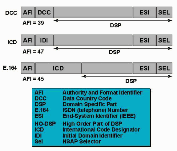
There are three types of private ATM addresses:
-
Data Country Code (DCC) AESA - The AFI is 39. These addresses are to be used in public networks. For example, the initial domain identifier (IDI) value 0x84.0f identifies the United States.
-
International Code Designator (ICD) AESA - The AFI is 47. These addresses are used in private organizations, and the ICD field indicates the code set or organization. Cisco uses by default ICD addresses.
-
NSAP encoding format for E.164 addresses - The authority and format identifier (AFI) is 45. These addresses are used in establishing ISDN calls by public networks, and they are normally used in public telephony.
All three are illustrated in the graphic below:

Cisco Auto-Configured Addresses
The following graphic shows the format for Cisco auto-configured ATM addresses.

We can see that ICD addresses (AFI = 47) are used. The ICD reserved for Cisco is 0x0091. Therefore, any ATM addresses starting by 0x47.00.91 have been assigned by Cisco.
The main idea is to use Media Access Controller (MAC) addresses in order to create unique default ATM addresses. It is important to understand that MAC addresses here should be seen as a pool of unique numbers. The user can configure the ATM addresses manually, bypassing the default settings. We will assume in this document that the user left the auto-configured addresses.
In the High Order Domain Specific Part, 13 bytes can be used. The three first are identifying Cisco addresses (0x47.00.91). As we have 10 remaining bytes, the first four after 0x47.00.91 have been set to 81.00.00.00.
Then, MAC addresses are used in the default ATM prefixes (13 bytes). As an example, on a 8540MSR:
Stan#show atm addresses

Switch Address(es):
  47.0091810000000060705A8F01.0060705A8F01.00 active

Soft VC Address(es):
  47.0091.8100.0000.0060.705a.8f01.4000.0c80.0000.00 ATM0/0/0
  47.0091.8100.0000.0060.705a.8f01.4000.0c80.0010.00 ATM0/0/1
We can see that:
-
The switch address is a Cisco address; it starts with 0x47.00.91
-
The next four bytes are 0x81.00.00.00, assigned by Cisco.
-
The MAC address allocated to the switch is 0x00.60.70.5a.8f.01
-
Each ATM interface is allocated an end-system identifier (ESI) such as 0x40.00.0c.80.00.00
-
The MAC address 0x00.60.70.5a.8f.01 is also used as the switch ESI
The following is an end-system example on a LAN Emulation (LANE) module:
Alcazaba#show lane default-atm-addresses
interface ATM2/0:
LANE Client:        47.00918100000001604799FD01.0050A219F038.**
LANE Server:        47.00918100000001604799FD01.0050A219F039.**
LANE Bus:           47.00918100000001604799FD01.0050A219F03A.**
LANE Config Server: 47.00918100000001604799FD01.0050A219F03B.0
Note: ** is the subinterface number byte in hexadecimal notation.
The prefix (the 13 first bytes) is derived from the directly attached switch. We can see that:
-
The prefix of the switch is: 0x47.00.91.81.00.00.00.01.60.47.99.FD.01
-
The MAC address of the switch is: 0x01.60.47.99.FD.01
-
The MAC addresses of the lane modules are in the range of 0x00.50.A2.19.F0.30-0x00.50.A2.19.F0.3F
Note: The MAC address of the switch seems to be a multicast MAC address (it starts with 0x01). This is not an issue when it comes to ATM addresses; the first bit has no real significance. Thus we can easily use any sequence of six bytes, including the MAC addresses usually not allocated for unique stations.
A following is a good example:
The following devices are attached to the same ATM switch:
47.00918100000001604799FD01.0050A219F03B.00
47.00918100000001604799FD01.00000C409823.00
A Brief Word on PNNI
As we have automatic ATM address assignment, we would like to have a "plug and play" network. In other words, we would like to have a switch reachable as soon as it is plugged in. This can easily be achieved by setting the PNNI peer group id to 0x49.00.91.81.00.00.00 (common to all Cisco ATM switches). This is why there is a 56-bit prefix: 56-bit covers the first seven bytes of the prefix.
Related Information
Contact Cisco
- Open a Support Case

- (Requires a Cisco Service Contract)
 Feedback