Understanding Transparent and Translation Modes With FRF.8
Available Languages
Contents
Introduction
The Frame Relay Forum (FRF) publishes implementation agreements or standards for Frame Relay networks to promote interoperability. FRF.8 specifies Frame Relay to ATM service interworking. Our network topology uses three components:
-
Router endpoint with a serial interface configured for Frame Relay encapsulation.
-
ATM endpoint.
-
Network switch or Cisco router that implements the interworking function (IWF) to allow the two endpoints to communicate.

Section 5 of the FRF.8 agreement discusses two modes of upper-layer protocol encapsulation. This encapsulation refers to the header that identifies the protocol carried within the protocol data unit (PDU), allowing the receiver to properly process the incoming packet. FRF.8 defines two modes - translation and transparent. Selecting one of these modes at the interworking function determines the encapsulation we need to configure on our ATM endpoint.
This document illustrates the packet-level differences between transparent and translation mode to assist with troubleshooting end-to-end connectivity issues with FRF.8 implementations.
Prerequisites
Requirements
There are no specific requirements for this document.
Components Used
This document is not restricted to specific software and hardware versions.
Conventions
For more information on document conventions, refer to the Cisco Technical Tips Conventions.
Understanding Layer-2 Headers
Frame Relay and ATM are layer 2 protocols for networking interfaces. Both protocols use two different headers at layer 2:
-
Upper-layer protocol encapsulation header—Communicates the protocol encapsulated and transported in the frame or cell. Defined by Request for Comments (RFC) 1490 and FRF 3.2 for Frame Relay, and RFCs 1483 and 2684 for ATM.
-
Address header—Communicates the layer 2 address (Data-link connection identifier [DLCI] or virtual path identifier/virtual channel identifier [VPI/VCI]) as well as loss priority and congestion indication values. Defined by Q.922 (typically two bytes) for Frame Relay and a five-byte cell header for ATM.
Note: FRF.8 translation and transparent modes are concerned with the encapsulation header.
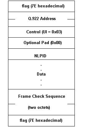
The following diagram illustrates a sample Frame Relay packet with the Q.922 address header and the control and network layer protocol identification (NLPID) fields of the upper-layer protocol encapsulation header.

Understanding Frame Relay IETF and Cisco Encapsulation
Before we look at some debug commands to illustrate the FRF.8 modes, we first need to understand Frame Relay encapsulation. Cisco router interfaces support two protocol encapsulations, Cisco and the Internet Engineering Task Force (IETF), which you can select with the encapsulation frame-relay [ietf] command. These encapsulations include two IETF formats and one Cisco format. Let's look at these in more detail.
IETF Encapsulation
RFCs 1490 and 2427 define IETF encapsulation for Frame Relay. They specify how to use an NLPID value. The ISO/International Electrotechnical Commission (IEC) TR 9577 document defines NLPID values for a select number of protocols, including:
| Value | Description |
|---|---|
| 0x00 | Null network layer or inactive set (not used with Frame Relay) |
| 0x80 | Subnetwork Access Protocol (SNAP) |
| 0x81 | ISO CLNP |
| 0x82 | ISO End System-to-Intermediate System (ES-IS) |
| 0x83 | ISO Intermediate System-to-Intermediate System (IS-IS) |
| 0xCC | Internet IP |
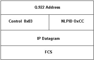
Protocols with a defined NLPID value use a short-form header, as shown below.

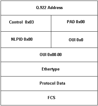
Protocols without a defined NLPID value use a SNAP header and indicates so with an NLPID value of 0x80, as shown below.

The router automatically chooses which IETF form to use by the following rule: If there is an NLPID value for the protocol, use the short-form. If not, use the long form.
Cisco Encapsulation
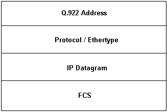
Cisco encapsulation uses a two-byte control field with EtherType values to identify the layer 3 protocol. Cisco encapsulation for IP uses the two-byte EtherType of 0x0800, followed by the IP datagram.

Translation and Transparent Mode Defined
The FRF.8 implementation agreement uses the following wording to describe translation and transparent modes.
-
Transparent Mode (Mode 1)—When encapsulation methods do not conform to the standards cited in Mode 2 but they are compatible between terminal equipment, the interworking function (IWF) forwards the encapsulations unaltered. It does not perform any mapping, fragmentation or reassembly.
-
Translation Mode (Mode 2)—Encapsulation methods for carrying multiple upper layer user protocols (for example, LAN to LAN) over a Frame Relay PVC and an ATM PVC conform to the standard FRF 3.2 and RFC 2684, respectively. The IWF performs mapping between the two encapsulations due to the incompatibilities of the two methods. Translation Mode supports the interworking of internetworking (routed and/or bridged) protocols.
Now let's issue Cisco IOS® Software show and debug commands to understand how we apply these modes to an actual implementation of FRF.8 on Cisco routers.
Configure
Network Diagram
This section uses this network setup:

Configurations
This section uses these configurations:
| 3620-1 |
|---|
interface Serial1/0 ip address 10.10.10.1 255.255.255.0 encapsulation frame-relay IETF frame-relay map ip 10.10.10.2 25 frame-relay interface-dlci 25 frame-relay lmi-type ansi |
| 7206B |
|---|
frame-relay switching ! interface Serial4/3 no ip address encapsulation frame-relay IETF frame-relay interface-dlci 50 switched frame-relay lmi-type ansi frame-relay intf-type dce ! interface ATM5/0 no ip address atm clock INTERNAL no atm ilmi-keepalive pvc 5/50 vbr-nrt 100 75 oam-pvc manage encapsulation aal5mux fr-atm-srv ! connect SIVA Serial4/3 50 ATM5/0 5/50 service-interworking |
| 7500-A |
|---|
interface atm 4/0/0.50 multi ip address 10.10.10.2 255.255.255.0 pvc 5/50 vbr-nrt 100 75 30 protocol ip 10.10.10.1 |
Note: When illustrating the two modes, we make two configuration changes by issuing the commands encapsulation aal5nlpid on the ATM endpoint and no service translation on the IWF router.
debug Commands
The interworking device performs its function interrupt mode and thus we cannot capture debug atm packet output since these debugs work with process-level packet only. We must run debugs on the two ends to capture the format of the packets.
Note: Before issuing debug commands, refer to Important Information on Debug Commands.
-
debug frame-relay packet int serial 1/0 - Captures a packet-level decode on the frame-relay endpoint.
-
debug atm packet int atm 4/0/0.50 - Captures a packet-level decode on the ATM endpoint.
-
debug atm error - Captures encapsulation errors or mismatches.
Translation Mode Illustrated
When we use the connect command to link the ATM and Frame Relay PVCs, the IWF router automatically uses translation mode. Use the show connect name command to confirm this.
We can initiate a ping from the Frame Relay endpoint to the ATM endpoint using the following configuration:
-
Configure the Frame relay endpoint with IETF encapsulation.
-
Configure the IWF router for translation mode.
-
Configure the ATM endpoint with AAL5SNAP encapsulation.
3620-1.9# ping 10.10.10.2
Type escape sequence to abort.
Sending 5, 100-byte ICMP Echos to 10.10.10.2, timeout is 2 seconds:
!!!!!
Success rate is 100 percent (5/5), round-trip min/avg/max = 36/36/40 ms
Our pings are successful. Let's look at the packet headers on each endpoint.
debug frame-relay packet on Frame Relay Endpoint
3620-1.9#
*Apr 4 11:13:20.978: Serial1/0(o): dlci 50(0xC21), NLPID 0x3CC(IP),    datagramsize 104
*Apr 4 11:13:21.014: Serial1/0(i): dlci 50(0xC21), NLPID 0x3CC(IP),    datagramsize 104
*Apr 4 11:13:21.014: Serial1/0(o): dlci 50(0xC21), NLPID 0x3CC(IP),    datagramsize 104
*Apr 4 11:13:21.050: Serial1/0(i): dlci 50(0xC21), NLPID 0x3CC(IP),    datagramsize 104
*Apr 4 11:13:21.050: Serial1/0(o): dlci 50(0xC21), NLPID 0x3CC(IP),    datagramsize 104
*Apr 4 11:13:21.086: Serial1/0(i): dlci 50(0xC21), NLPID 0x3CC(IP),    datagramsize 104
*Apr 4 11:13:21.090: Serial1/0(o): dlci 50(0xC21), NLPID 0x3CC(IP),    datagramsize 104
*Apr 4 11:13:21.122: Serial1/0(i): dlci 50(0xC21), NLPID 0x3CC(IP),    datagramsize 104
*Apr 4 11:13:21.126: Serial1/0(o): dlci 50(0xC21), NLPID 0x3CC(IP),    datagramsize 104
*Apr 4 11:13:21.162: Serial1/0(i): dlci 50(0xC21), NLPID 0x3CC(IP),    datagramsize 104
Referring back to our discussion of IETF encapsulation, we see that the ping packet uses the short-form encapsulation header since the IP protocol is assigned the NLPID value of 0xCC.
debug atm packet on ATM Endpoint
7500-1.5#
1w3d: ATM4/0/0.50(I):
VCD:0xD VPI:0x5 VCI:0x32 Type:0x0 SAP:AAAA CTL:03 OUI:000000 TYPE:0800         Length:0x70
1w3d: 4500 0064 004B 0000 FE01 9437 0A0A 0A01 0A0A 0A02 0800 0C14 08FE 246F    0000
1w3d: 0000 B1E8 92E0 ABCD ABCD ABCD ABCD ABCD ABCD ABCD ABCD ABCD ABCD ABCD    ABCD
1w3d: ABCD ABCD ABCD ABCD ABCD ABCD ABCD ABCD ABCD ABCD ABCD ABCD ABCD ABCD    ABCD
1w3d: ABCD ABCD ABCD ABCD ABCD
1w3d:
1w3d: ATM4/0/0.50(O):
VCD:0xD VPI:0x5 VCI:0x32 DM:0x0 SAP:AAAA CTL:03 OUI:000000 TYPE:0800           Length:0x70
1w3d: 4500 0064 004B 0000 FF01 9337 0A0A 0A02 0A0A 0A01 0000 1414 08FE 246F    0000
1w3d: 0000 B1E8 92E0 ABCD ABCD ABCD ABCD ABCD ABCD ABCD ABCD ABCD ABCD ABCD    ABCD
1w3d: ABCD ABCD ABCD ABCD ABCD ABCD ABCD ABCD ABCD ABCD ABCD ABCD ABCD ABCD    ABCD
1w3d: ABCD ABCD ABCD ABCD ABCD
For routed protocol data units (PDUs), AAL5SNAP encapsulation uses an OUI value of 0x000000 and an Ethertype value (such as 0x0800 for IP) for the type field. Refer to Multiple Routed Protocols Over ATM PVCs Using LLC Encapsulation for further information.
Our debugs illustrate how the IWF translates between the Frame Relay NLPID header and the AAL5SNAP ATM header.
Transparent Mode Illustrated
To illustrate transparent mode, let's change only the mode on the IWF router. Issue the no service translation command to explicitly configure transparent mode.
7200-2.4(config)# connect SIVA
7200-2.4(config-frf8)# no service translation
Issue the show connect name command to confirm your change.
7200-2.4# show connect name SIVA

FR/ATM Service Interworking Connection: SIVA
Status - UP
Segment 1 - Serial4/3 DLCI 50
Segment 2 - ATM5/0 VPI 5 VCI 50
Interworking Parameters -
no service translation
efci-bit 0
de-bit map-clp
clp-bit map-de
Our pings between the two routers now fail. Using debug atm packet and debug atm error, we see the reason for the ping failure - the original NLPID header is carried right through the IWF and reaches the ATM endpoint, which is configured with AAL5SNAP and does not understand the NLPID values.
7500-1.5#
1w3d: ATM4/0/0.50(I):
VCD:0xD VPI:0x5 VCI:0x32 Type:0x0 SAP:03CC CTL:45 Length:0x6A
1w3d: 0000 6400 4A00 00FF 0193 380A 0A0A 010A 0A0A 0208 0058 3603 6F10 EA00 0000
1w3d: 00B1 8E60 2CAB CDAB CDAB CDAB CDAB CDAB CDAB CDAB CDAB CDAB CDAB CDAB CDAB
1w3d: CDAB CDAB CDAB CDAB CDAB CDAB CDAB CDAB CDAB CDAB CDAB CDAB CDAB CDAB CDAB
1w3d: CDAB CDAB CDAB CDAB CD43
1w3d:
1w3d: ATM(ATM4/0/0.50): VC(13) Bad SAP received 03CC
With AAL5SNAP encapsulation, the ATM interface looks for destination service-access-point (DSAP) and source service access point (SSAP) values of AA to indicate that the SNAP header follows. Instead, in the same byte location, we receive the control (0x03) and NLPID (0xCC for IP) values of the original Frame Relay header.
We can correct this error condition by changing the ATM encapsulation to AAL5NLPID. Now, both endpoints are using the same encapsulation, so our pings are successful.
7500-1.5(config)# interface atm 4/0/0.50
7500-1.5(config-subif)# pvc 5/50
7500-1.5(config-if-atm-vc)# encapsulation ?
 aal5ciscoppp Cisco PPP over AAL5 Encapsulation
 aal5mux AAL5+MUX Encapsulation
 aal5nlpid AAL5+NLPID Encapsulation
 aal5snap AAL5+LLC/SNAP Encapsulation

1w3d: %SYS-5-CONFIG_I: Configured from console by console

7500-1.5# show debug
Generic ATM:
 ATM packets debugging is on
 ATM errors debugging is on
7500-1.5#
1w3d: ATM4/0/0.50(I):
VCD:0xD VPI:0x5 VCI:0x32 Type:0x2 NLPID:0x03CC Length:0x6A
1w3d: 4500 0064 0054 0000 FE01 942E 0A0A 0A01 0A0A 0A02 0800 F9A6 1C05 2248 0000
1w3d: 0000 B1F5 9460 ABCD ABCD ABCD ABCD ABCD ABCD ABCD ABCD ABCD ABCD ABCD ABCD
1w3d: ABCD ABCD ABCD ABCD ABCD ABCD ABCD ABCD ABCD ABCD ABCD ABCD ABCD ABCD ABCD
1w3d: ABCD ABCD ABCD ABCD ABCD
1w3d:
1w3d: ATM4/0/0.50(O):
VCD:0xD VPI:0x5 VCI:0x32 DM:0x0 NLPID:0x03CC Length:0x6A
1w3d: 4500 0064 0054 0000 FF01 932E 0A0A 0A02 0A0A 0A01 0000 01A7 1C05 2248 0000
1w3d: 0000 B1F5 9460 ABCD ABCD ABCD ABCD ABCD ABCD ABCD ABCD ABCD ABCD ABCD ABCD
1w3d: ABCD ABCD ABCD ABCD ABCD ABCD ABCD ABCD ABCD ABCD ABCD ABCD ABCD ABCD ABCD
1w3d: ABCD ABCD ABCD ABCD ABCD
Related Information
Contact Cisco
- Open a Support Case

- (Requires a Cisco Service Contract)
 Feedback