Bridged PVC Connection Between a Router and a Catalyst Switch
Available Languages
Contents
Introduction
This document illustrates a sample configuration between a router and a Catalyst Switch with a LANE module, using Logical Link Control (LLC) encapsulation. Router A routes on the Ethernet and performs bridging between the Catalyst switch . No mapping is done on the permanent virtual circuit (PVC) for bridging. This is because all VCs on a bridged subinterface are automatically used for bridging.
LAN Emulation (LANE) modules used in the Catalyst 5000 and Catalyst 6000 Family switches cannot use routed RFC 1483. This document demonstrates bridged RFC 1483 ![]() between a Catalyst 5000 Family switch and a router. In the sample configuration, Router A is used as a Layer 2 device, with end stations attached to their Ethernets.
between a Catalyst 5000 Family switch and a router. In the sample configuration, Router A is used as a Layer 2 device, with end stations attached to their Ethernets.
Note: This document focuses on PVC configurations on Cisco routers running Cisco IOS® software. For PVC configuration examples on Cisco WAN switches, refer to WAN Switches Technical Support.
Prerequisites
Requirements
There are no specific requirements for this document.
Components Used
The information in this document is based on these software and hardware versions:
-
Cisco IOS® Software Release 11.2 or later is needed for integrated routing and bridging (IRB). The command syntax was enhanced in Cisco IOS Software Release 11.3T. The configurations in this document use the enhanced syntax.
-
Catalyst 5000 or 6000 Family switch with a LANE module.
The information in this document was created from the devices in a specific lab environment. All of the devices used in this document started with a cleared (default) configuration. If your network is live, make sure that you understand the potential impact of any command.
Conventions
For more information on document conventions, refer to Cisco Technical Tips Conventions.
Bridged RFC 1483
When you use PVCs, there are two ways to carry multiple protocols over Asynchronous Transfer Mode (ATM).
-
virtual circuit (VC) multiplexingâThe user defines one PVC per protocol. This method uses more VCs than LLC encapsulation, but reduces overhead because a header is not necessary.
-
Logical Link Control (LLC) / Subnetwork Access Protocol (SNAP) EncapsulationâThe user multiplexes multiple protocols over a single ATM VC. The protocol of a carried protocol data unit (PDU) is identified by prefixing the PDU with an LLC / SNAP header.
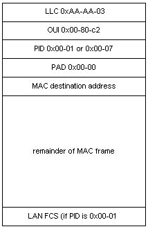
LLC / SNAP headers use either a routed format or a bridged format. The format of the ATM Adaptation Layer 5 (AAL5) common part convergence sublayer (CPCS)-PDU Payload field for bridged Ethernet/802.3 PDUs is shown in this diagram:

A bridged format does not necessarily mean that the encapsulated protocol is not routable. It is typically used when one side of the link supports only the bridged-format PDUs, such as in a connection between a router and a Catalyst switch in a corporate campus ATM network. In this application, the router interface typically serves as the default gateway for the remote users. Then, integrated routing and bridging (IRB), routed bridge encapsulation (RBE) or bridged-style PVCs (BPVCs) provide the mechanism for routing traffic off-network.
These protocols allow the ATM interface to receive bridged-format PDUs. However, they have important differences in performance. Cisco recommends that you consider RBE when the configuration supports it.
Configure
In this section, you are presented with the information to configure the features described in this document.
Note: To find additional information on the commands used in this document, use the Command Lookup Tool (registered customers only) .
Network Diagram
This document uses this network setup:

Network Diagram Notes:
-
In this example 1/119 is switched to 1/119 by the ATM switch.
-
The IP address on the switch is the address of the sc0 interface which is configured in Virtual LAN (VLAN) 1.
-
This example uses IRB for routing off-network. Refer to Configuring Integrated Routing and Bridging in the Cisco IOS Bridging and IBM Networking Configuration Guide for guidance on using the IRB commands. See the Related Information
Revision History
| Revision | Publish Date | Comments |
|---|---|---|
1.0 |
15-Nov-2007 |
Initial Release |
Contact Cisco
- Open a Support Case

- (Requires a Cisco Service Contract)
 Feedback