ATM PVC, SVC, Soft-PVC, and PVP Frequently Asked Questions
Available Languages
Contents
Q. What is an ATM Permanent Virtual Circuit (PVC)?
A. A PVC is a circuit that a network operator over an ATM-switched network between a specific source and a specific destination manually provisions. A PVC is provisioned in order to last from a month to several years, or until the service is terminated. Refer to RFC 1483
for more information.
Note: PVC is also known as Permanent Virtual Channel.
Q. When can PVCs be implemented?
A. A network operator implements PVCs on leased lines from ATM providers. An ATM PVC provides the end user with a non-redundant circuit through the Service Provider cloud. This circuit is provisioned with the bandwidth that the end user paid for and needs.
Q. What are the typical PVC implementations?
A. There are two typical PVC implementations:
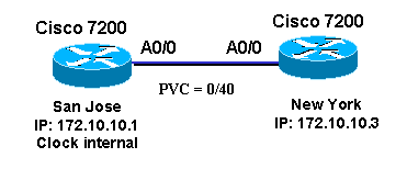
Back-to-Back—This is usually used in a lab or non production environment. This must occur in order to set up a PVC in a back-to-back topology:
The same virtual path identifier/virtual channel identifier (VPI/VCI) pair needs to be used on both end devices. In this example, VPI/VCI (or PVC) is 0/40.
One router must be configured in order to clock the TX signal from the internal oscillator. By default, Cisco routers clock the TX signal by the clock received on the line. This is an illustrated example.

San Jose
New York
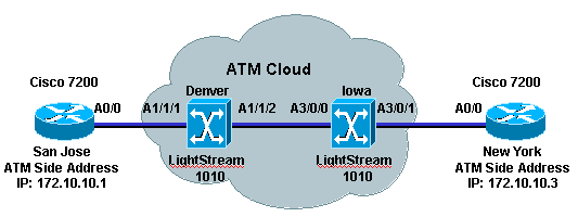
Through a Telco cloud—Usually used in a production environment when customers use leased lines from ATM Service Providers.

The ATM Service Provider must provide the VPI/VCI information that both end devices use in order to set up a PVC. The VPI/VCI pairs do not have to be the same. The ATM Service Provider configures cross-connections in the switches between the VPI/VCI pairs.
Q. What are the different PVC encapsulation types?
A. These are the four different PVC encapsulation types:
aal5ciscoppp—For Cisco proprietary PPP over ATM, aal5ciscoppp supports only Cisco routers with ATM or asymmetric digital subscriber line (ADSL) interfaces. Use this type of encapsulation when PPP authentication is desired.
aal5mux—AAL5 MUX encapsulation supports only a single protocol, IP or IPX, per PVC.
aal5nlpid—AAL5 Network Layer Protocol Identification (NLPID) encapsulation allows ATM interfaces in order to interoperate with High-Speed Serial Interfaces (HSSIs) that use an ATM data service unit (ADSU) and that run ATM-Data Exchange Interface (DXI).
aal5snap—AAL5 Logical Link Control/Subnetwork Access Protocol (LLC/SNAP) encapsulation supports Inverse ARP and incorporates the LLC/SNAP that precedes the protocol datagram. This allows the multiple protocols to transverse the same PVC.
Note: aal5snap is the default encapsulation and the most widely used because it allows multiple protocols to be carried over one PVC.
Q. What are the differences between Routed RFC 1483 PVCs and Bridged RFC 1483 PVCs?
A. In most cases, the differences refer to the LLC Encapsulation SubNetwork Attachment Point (SNAP) PVCs. Routed PVCs have only the 802.2 LLC header (0xFE-FE-03), which the 802.1a SNAP field can possibly follow. Bridged PVCs have the 802.1 header (0xAA-AA-03) and several other fields that include a metropolitan-area network destination address.
Refer to Multiple Routed Protocols Over ATM PVCs Using LLC Encapsulation for an example of an RFC 1483 routed configuration. Refer to Basic PVC Configuration Using Bridged RFC 1483 for a Bridged RFC 1483 configuration.
Q. How do I need to configure my ATM interfaces on a Cisco router to use PVCs?
A. You can configure your ATM interface on a Cisco router that uses a routed or bridged PVC configuration. This is an example of a routed RFC 1483 configuration.

San Jose New York Note: Both routers are either point-to-point or multipoint interfaces. The previous example demonstrates the configuration for both types. The ATM Adaptation Layer (AAL) Encapsulation is aal5snap by default. The ATM service type is Unspecified Bit Rate (UBR) by default. These configurations are from a Cisco 7200 router and it is assumed that the ATM network administrator/ ISP has given the customer VPI/VCI pairs for both ends of the circuit that the routers terminate. In the case of the previous example, the VPI/VCI pairs given to the customer are 0/40 for router San Jose and and 0/50 for router New York.
Q. What are the VPI/VCI ranges that the different Cisco router platforms use?
A. The number of VPI/VCI values that can be used in a Cisco platform can vary as it depends on the platform and configuration. For example, Inverse Multiplexing for ATM (IMA) configurations use only VPI sub-ranges 0-15, 64-79, 128-143, 192-207. Typically, the ATM Five-Byte Cell Header includes 8 bits for VCI and 16 bits for VPI. This picture shows how the ATM Five-Byte Cell Header is formed:

Most platforms use 8 bits for a VPI, that give a range of 0 to 255 and 16 bits for a VCI, that give a range of 0 - 65535. Understanding the Maximum Number of Active Virtual Circuits on Cisco ATM Router Interfaces provides very detailed information of the VPI/VCI ranges for different platforms. Refer to What is the Virtual Path Identifier/Virtual Channel Identifier (VPI/VCI) range for the IMA cards? for more information about IMA VPI/VCI ranges.
Q. Which PVC configuration style is recommended for Cisco routers?
A. Cisco introduced the ATM PVC configuration in Cisco IOS® Software Release 10.0 that uses the atm pvc vcd vpi vci aal-encap interface command. This is now known as old-style PVC configuration. In Cisco IOS Software Release 11.3 T, Cisco introduced a new way to configure ATM PVCs that uses the new pvc [name] vpi/vci [ilmi | qsaal |smds] command. Refer to New VC Configuration for more information. This new way that configures ATM PVCs allows for more flexibility and greater capability. Some of the limitations of the old-style are the lack of support for both Operation And Management (OAM) and Low Latency Queueing (LLQ).
This table shows Cisco IOS Software support the ATM PVC configuration syntax supported:
Old Style PVC configuration (earlier than Cisco IOS Software Release 11.3 T) New Style PVC configuration (Cisco IOS Software Release 11.3T and later)
Q. What is a Switched Virtual Circuit (SVC)?
A. An SVC is an on-demand connection that is dynamically established by end devices through the Network-Network Interface (NNI) signaling method. There must be an ATM switch between the end-devices that dynamically route the call through the ATM cloud. Network operators do not have to manually configure every ATM switch in the path. If there is a link failure, the end-device must reinitiate the SVC call. SVCs are also torn down after being idle for a specified period of time (default idle time-out for Cisco routers is 300 seconds). Refer to these documents in order to learn how to configure SVCs on different Cisco platforms:
Configuring RFC 1483 ATM SVCs Without ILMI for Address Registration
Configuring Classical IP over ATM in an SVC Environment on an ARM Module
Note: SVC is also know as Switched Virtual Channel.
Q. When can SVCs be implemented?
A. A network operator that implements LAN Emulation (LANE) or Classical IP (CLIP) over ATM (RFC 1577) establishes SVCs. Network operators do not have to use LANE or CLIP in order to establish SVCs. The network operator can configure the 20-byte ATM address in order to protocol (IP, IPX) mappings on all end-devices. This allows the end-device to use UNI signaling in order to set up a call to a remote end device.
Q. What is a Soft-Permanent Virtual Circuit (Soft-PVC)?
A. A Soft-PVC is a PVC that is established manually across a UNI and dynamically across a User-to-Network Interface (NNI). The Soft-PVC stays up through the ATM network at all times. If there is an ATM switch failure, the Soft-PVC reroutes over the ATM network. Soft-PVC configuration provides the best of PVCs and SVCs because it provides the flexibility of SVCs in the core of the network and the stability of PVCs at the edge.
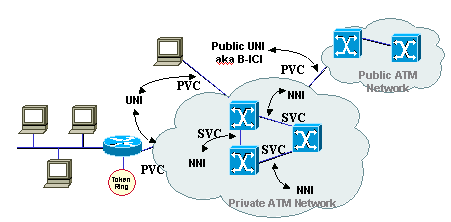
Soft-PVCs can be configured only in ATM switches. Refer to Configuring SVCs, PVCs, Soft PVCs, PVPs, and VP Tunnels for more detailed information on how to configure Soft-PVCs. This figure shows where the PVCs and SVCs are configured.

Q. When can Soft-PVCs be implemented?
A. A network operator needs to implement Soft-PVCs when the ATM network is fully meshed. The network operator needs only to configure one of the ATM switches connected to an end device.
Q. What is an ATM Permanent Virtual Path (PVP)?
A. A PVP is a connection that is manually configured by a network operator and is provisioned by the configuration of ATM switch-to-switch cells that uses only the VPI in the cell header. Like the SVCs, the PVPs are provisioned for the life of the service. PVPs are used as multiplexing/de-multiplexing points on ATM switches for VCs (Virtual Circuits) from various end devices. Refer to Configuring SVCs, PVCs, Soft PVCs, PVPs, and VP Tunnels for more information.
Q. When can PVPs be implemented?
A. PVPs reduce the switching time in ATM switches as the cells are switched based on their VPIs only. A network operator can configure PVPs on ATM switches when a set of VCs that use the same VPI needs to be switched from one site to another. Some examples are LANE, Classical IP (RFC 1577) and any implementation that requires the use of SVCs.
Q. What is a typical PVP implementation?
A. A typical PVP implementation is used for multiplexing ATM traffic. ATM network operators typically use this in order to reduce the switching time in ATM switches. A common topology is shown in this network diagram.

Q. Can Cisco routers be configured for SVCs over PVPs?
A. No, because Cisco routers cannot establish SVCs over PVP connections. Routers are not capable of the performance of UNI Signaling over any VPI other than 0. Most ATM Service Providers do not allow customers signaling over VPI 0. The router needs to be connected to an ATM switch which is configured with a PVP into the ATM Service Provider cloud. A PVP can be configured on routers so that the whole VP can be traffic-shaped in order to prevent the network operator from the need to configure traffic shaping for each PVC that uses the same VPI.
Q. Can Cisco ATM switches be configured to switch cells from one PVP to another PVP on the same interface?
A. Yes. Cisco ATM switches can be programmed in order to map one PVP to another PVP on the same interface. This is an example of a Cisco ATM Switch configuration:
interface ATM0/0/0
 no ip address
 atm pvp 20  interface  ATM0/0/0 10
Q. Why does the router show the error message %ATM: PVP <vpi#> removal failed when a PVP is removed?
A. This is due to Cisco bug ID CSCdv83829 (registered customers only). The ATM PVP is not removed even though there is no PVC configured for that VPI. This issue is resolved in Cisco IOS Software Releases 12.1(12), 12.2(7) and later IOS images.
Q. Why do the ATM Subinterfaces appear to flap when oam-pvc manage is configured?
A. OAM loopback cells are not traffic-shaped by the ATM adapters. The ATM provider can possibly police and drop the OAM loopback cells that violates the traffic contract. The ATM provider has to increase its Cell Delay Variation Tolerance (CDVT) in order to address this issue.
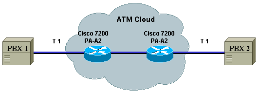
Q. Can the PA-A2 CES adapters support back-to-back connectivity on the T1 ports?
A. No. The PA-A2 CBR ports are designed for Circuit Emulation Services (CES) only. This is an example of how they can be used:

Q. What is ATM Traffic Shaping?
A. A network operator needs to configure the end-device, router, in order to transmit ATM cells at a rate that conforms to the Quality of Service (QoS) that was purchased from an ATM Internet Service Provider (ISP). The service purchased or requested needs to be based on the type of service the user needs:
voice
video
data
There are currently five service classes:
Available Bit Rate (ABR)—This is a service class where ATM switches make no guarantee of cell delivery, but do guarantee a minimum bit rate and that cell loss is kept as low as possible with the use of a feedback mechanism. The ABR service category is designed for VCs that carry file transfers and other bursty, non-real-time traffic that requires a minimum amount of bandwidth, specified via a minimum cell rate, in order to be available while the VC is configured and active. Refer to Understanding the Available Bit Rate (ABR) Service Category for ATM VCs for a configuration and more detailed information on ABR.
Constant Bit Rate (CBR)—This is a service class where cells are transmitted in a continuous bit-stream in order to meet voice and video QoS needs. The CBR service class is designed for ATM virtual circuits (VCs) that need a static amount of bandwidth that is continuously available for the duration of the active connection. An ATM VC configured as CBR can send cells at peak cell rate (PCR) at any time and for any duration. It also can send cells at a rate less than the PCR or even emit no cells. The configuration on CBR may vary with different platforms. Refer to Understanding the CBR Service Category for ATM VCs for a detailed understanding and configuration of CBR.
Unspecified Bit Rate (UBR)—This is a service class where the network management makes no Quality of Service (QoS) commitment. It models the best-effort service that the Internet normally provides and is suitable for applications tolerant to delay and does not require real-time responses. Examples include email, fax transmission, file transfers, Telnet, LAN and remote office interconnections. Refer to Understanding the UBR Service Category for ATM Virtual Circuits for a detailed understanding and configuration of UBR services. Cisco provides a variant of this service class and it is called UBR+. The main advantage of the UBR+ service class is that it allows an ATM end-system to signal a minimum cell rate to an ATM switch in a connection request, and the ATM network attempts to maintain this minimum as an end-to-end guarantee. Refer to Understanding the UBR+ Service Category for ATM VCs.
Variable Bit Rate - Non-Real Time (VBR-nrt)—This service class is used in order to transmit non-real-time applications that are bursty in nature. The traffic characteristics are defined in terms of the Peak Cell Rate (PCR), Sustained Cell Rate (SCR), and Minimum Burst Size (MBS). Refer to Understanding the VBR-nrt Service Category and Traffic Shaping for ATM VCs for a detailed information and configuration on VBR-nrt.
Variable Bit Rate - Real Time (VBR-rt)—This service class is used in order to transmit real-time data that is sensitive to time delays, like compressed voice over IP and video conferencing. VBR-rt, as well as VBR-nrt, are characterized by a PCR, SCR, and MBS. Refer to Understanding the Variable Bit Rate Real Time (VBR-rt) Service Category for ATM VCs for a detailed information and configuration on VBR-rt.
Refer to Traffic Management for more detailed information on ATM traffic shaping.
Q. What is ATM Traffic Policing?
A. ATM Traffic Policing is the means by which ATM network administrators can enforce penalties on user traffic that does not conform to the traffic contract purchased for the service categories ABR, CBR, UBR, VBR-nrt, and VBR-rt. The administrators have to configure the ATM switches that comprise the path of the circuit to either tag, change ATM header CLP-bit to 1, or drop cells transmitted at a rate that does not conform to the parameters of the service type. Refer to Traffic Policing and Configuring and Traffic Policing Point-to-Multipoint PVC Connections on LightStream 1010, Catalyst 8510MSR and Catalyst 8540MSR Switches for more detailed information on ATM Traffic Policing.
Q. Does Cisco Discovery Protocol (CDP) work with RFC 1483 encapsulation?
A. CDP support is introduced in Cisco IOS Software Release 12.2(8)T. Currently, CDP is only supported on AAL5SNAP RFC 1483 PVCs and only on point-to-point subinterfaces. Multipoint subinterface support is not planned as yet. This is an example that shows CDP on AAL5snap PVCs:

Note: Router1 and Router2 are 2 7140 routers that run Cisco IOS Software Release 12.2(8)T.
Router1 Router2 show cdp neighbors atm4/0.1 detail ------------------------- Device ID: router2 Entry address(es): IP address: 10.4.4.2 Platform: cisco 7120-AE3, Capabilities: Router Interface: ATM4/0.1, Port ID (outgoing port): ATM1/0.1 Holdtime : 137 sec Version : Cisco Internetwork Operating System Software IOS (tm) EGR Software (C7100-JS-M), Version 12.2(8)T, RELEASE SOFTWARE (fc2) TAC Support: http://www.cisco.com/tac Copyright (c) 1986-2002 by cisco Systems, Inc. Compiled Wed 13-Feb-02 17:46 by ccai advertisement version: 2 router2#show cdp interface atm 1/0.1 ATM1/0.1 is up, line protocol is up Encapsulation ATM Sending CDP packets every 60 seconds Holdtime is 180 seconds router2#show cdp neighbors atm1/0.1 detail ------------------------- Device ID: router1 Entry address(es): IP address: 10.4.4.1 Platform: cisco 7140-2MM3, Capabilities: Router Interface: ATM1/0.1, Port ID (outgoing port): ATM4/0.1 Holdtime : 127 sec Version : Cisco Internetwork Operating System Software IOS (tm) EGR Software (C7100-JS-M), Version 12.2(8)T, RELEASE SOFTWARE (fc2) TAC Support: http://www.cisco.com/tac Copyright (c) 1986-2002 by cisco Systems, Inc. Compiled Wed 13-Feb-02 17:46 by ccai advertisement version: 2
Q. Does CDP work with NLPID encapsulation?
A. Cisco Discovery Protocol (CDP) support for aal5nlpid encapsulation is introduced in Cisco IOS Software Release 12.2T via Cisco bug ID CSCdz54297 (registered customers only). CDP is now supported on aal5snap and aal5nlpid PVCs and only on point-to-point subinterfaces.
Q. Can I use an LS1010 ATM Switch in order to route traffic between the Management Ethernet Port and an ATM PVC?
A. The LS1010 is an ATM switch that can only switch ATM Cells. While you can terminate an ATM PVC on the CPU port (ATM 0), you cannot use the Ethernet port in order to route user traffic or IP packets in any way between itself and the ATM PVC terminated on the CPU port. Also note that the LS1010 Ethernet port or the CPU port ATM 0 is only to be used for management purposes and not to route user traffic, as all processing on it is done by the CPU, process switched.
Q. Can I configure ATM PVC Switching (Cell Switching) on a router just like I configure Frame Relay switching (Frame Switching) for Frame Relay PVCs?
A. Unlike the capability to configure Frame Relay switching on a router with serial interfaces to act as a Frame Relay Switch, you cannot use a router equipped with ATM interfaces in order to act as an ATM Switch to switch ATM cells or ATM PVCs. The only place you can do that is at Layer 3 where you can terminate the Layer 3 protocol on the ATM interface along with other PVCs and perform routing / Layer 3 switching between the configured PVCs. In order to do cell switching you must use an ATM Switch like LS1010, 8510 MSR, or 8540 MSR.
Q. Can I configure Bridging between an Ethernet Port and an ATM PVC on an 8540?
A. Bridging between an Ethernet port and ATM PVC on an 8500 ATM Switch cannot be configured unless the 8500 is equipped with an ATM Router Module (ARM). When an ARM is installed, you can configure bridging between Ethernet and ATM ports that uses the configuration guidelines provided in LAN Emulation Using the ATM Router Module.
Q. How do I clear an SVC in an ATM switch?
A. Issue the clear atm atm-vc atm command, as shown in this example:
        d12-4-8540msr-27#clear atm atm-vc atm 1/0/0 1 ?
		<0-65535> Virtual Circuit Identifier (VCI)
Q. How can I remove an ATM sub-interface from the configuration?
A. The only way to totally remove a subinterface is to issue the no interface atm command, save the configuration, and then reload the router.
If you only delete the subinterface it without reloading the router, the subinterface is still present and, as a result, you cannot reconfigure it with another type. For instance, the old one always reappears.
Pivrnec#configure terminal
     Enter configuration commands, one per line. End with CNTL/Z.
     Pivrnec(config)#no interface atm 1/0.1
     Not all config may be removed and may reappear after reactivating the sub-interface
     Pivrnec(config)# exit
Pivrnec#show ip interface brief
Interface                  IP-Address      OK? Method Status                Protocol
<skip>
ATM1/0                     unassigned      YES NVRAM  down                  down
ATM1/0.1                   unassigned      YES unset  deleted               down
ATM1/1                     unassigned      YES NVRAM  down                  down
ATM1/2                     unassigned      YES NVRAM  down                  down

<skip>
Notice that the subinterface ATM1/0.1 still shows up even after it is removed from the configuration.
Pivrnec#write memory
Building configuration...
[OK]
Pivrnec#

Pivrnec#reload
Proceed with reload? [confirm]
After reload, you can confirm that subinterface ATM1/0.1 does not show up in the list of interfaces anymore.
Pivrnec#show ip interface brief
Interface                  IP-Address      OK? Method Status                Protocol
<skip>
ATM1/0                     unassigned      YES NVRAM  down                  down
ATM1/1                     unassigned      YES NVRAM  down                  down
ATM1/2                     unassigned      YES NVRAM  down                  down
<skip>
Q. When you use Cisco IOS Software Release 12.1(T) on the 3600 router, why does the ATM and IMA interfaces lose some of their VC configuration when the router reloads or has a power issue?
A. This problem is documented in Cisco bug ID CSCdt64050 (registered customers only) which states that the vc-per-vp command does not function properly. The reason is that when you configure ATM-IMA, if the vc-per-vp value is set to 1024 (or value other than 256) and the configuration is saved in NVRAM, the value of vc-per-vp is not reflected after reload. The vc-per-vp value goes back to 256 after reload.
There is no workaround but to upgrade to a Cisco IOS Software release with the fix for this issue.
The solution is to upgrade your Cisco IOS Software to one of these software releases: 12.2(15)ZN 12.2(17)B 12.2(4)PB 12.2(4)S 12.2(3)T, 12.2(3), or later that corresponds to your features.
For IMA interfaces this problem is documented in Cisco
bug ID CSCdt65959 (registered customers only) where the vc-per-vp value goes down after reload in ATM-IMA. The reason is that in ATM-IMA, when the vc-per-vp value is set to 1024 and when the configuration is saved in NVRAM, the value of vc-per-vp is not reflected after reload. The vc-per-vp value goes to 256 after reload.There is no workaround but to upgrade to a Cisco IOS Software release with the fix for this issue.
The solution is to upgrade your Cisco IOS Software release to one of these: 12.2(4)B 12.2(4)PB 12.2(4)S 12.2(3)T, 12.2(3), or later that corresponds to your features.
Related Information
Contact Cisco
- Open a Support Case

- (Requires a Cisco Service Contract)


 Feedback