Virtual Interfaces and Frequency Stacking Configuration on MC5x20S and MC28U Linecards
Available Languages
Contents
Introduction
Virtual interfaces (VI) and frequency stacking (FS) are two new features which allow user-configurable MAC domains and multiple frequencies on one physical connector. Virtual interfaces allow up to eight upstreams (USs) per downstream (DS). It links a US port to a physical connector. The other feature, frequency stacking, allows two frequencies to be configured on one physical connector.
The MC5x20S card can initially be configured to match the DS and US configuration of an existing card, and then the cable operator can modify their configurations according to their needs. This supports different DSxUS port ratios, as combining ratios evolve (1x6 » 1x4 » 1x1). The linecard can be used as a 1x1 for a business customer and as a 1x7 for residential customers.
FS reduces cabling per channel and gives the ability to grow a service area without modifying cable modem termination system (CMTS) connectivity.
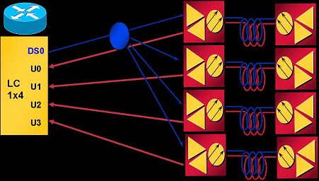
Figure 1 depicts one MAC domain from a MC5x20S linecard, wired up in a sparse mode configuration. Sparse mode refers to one or more fiber optic nodes feeding one US port.
Figure 1 – Sparse Mode Combining 
In the above combining scheme, one node is wired per US port. The MC5x20S card has four USs per MAC domain and five MAC domains per card, which equals twenty nodes per linecard. Using QPSK at 3.2 MHz channel width will give 5.12 Mbps per node (~4.4 Mbps usable).
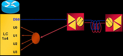
Figure 2 depicts one MAC domain from a MC5x20S linecard wired up in a dense mode configuration. Dense mode refers to one or more fiber optic nodes feeding more than one US port.
Figure 2 – Dense Mode Combining 
Figure 2 shows one node split to feed four US ports of one MAC domain. Because the MC5x20S has five MAC domains per card, this wiring serves five nodes per linecard. Because one physical area (node) feeds multiple US ports, each US port must be configured for non-overlapping frequencies. For example, U0 equals 20.0 MHz, U1 equals 23.2 MHz, U2 equals 26.4 MHz, and U3 equals 29.6 MHz with each port set at 3.2 MHz channel width. Using QPSK at 3.2 MHz channel width for each port will yield 20.48 Mbps for one node (~17.5 Mbps usable).
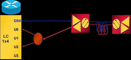
Figure 3 shows one example of frequency stacking with the MC5x20S linecard.
Figure 3 – Frequency Stacking 
Frequency stacking allows two frequencies to be configured on one connector, which allows less splitter loss and easier management.
Benefits
The benefits of using virtual interfaces are numerous. It allows an increase in US capacity on an as-needed basis in a flexible and dynamic manner. Grouping of DS and US according to a particular class of service (CoS)—such as a 1x1 for commercial customers and 1x7 for residential customers—might make more sense. This feature also simplifies installation of the MC5x20S card when replacing an existing linecard that uses 1x6 MAC domains. VIs also enhance availability when used in combination with Load Balancing (LB), because they can be used to create a large LB group for cable modems (CMs) to be balanced. For Load Balancing information, refer to Configuring Load Balancing for the Cisco CMTS.
Frequency stacking provides the benefit of eliminating two-way splitter loss and cabling complexity. This could save approximately 4 dB of attenuation. FS also enhances usability, when used in combination with VIs and LB, by easily assigning another frequency to the same physical port.
Restrictions
These restrictions are imposed on virtual interfaces:
-
No DS VIs.
-
There can only be one DS and up to eight USs in a domain. A MAC domain is one DS and its associated USs.
-
Only linecard VIs, not across linecards.
-
CSCeb10426 (registered customers only) —Simple Network Management Protocol (SNMP) support for VIs is not yet available.
-
You can only assign connectors that are not assigned or assign default settings from other domains—By default, all US ports have connectors assigned to them. When VIs are configured, the new US ports in the MAC domain can be assigned connectors that are not assigned or can be assigned other ports’ default connector assignments.
-
N+1 restrictions—All HCCP members of a group must be the same configuration in terms of VIs (MAC domain sizes). Once a connector is assigned to a port which is not its default assignment, the whole linecard will failover when a fault occurs.
-
High Availability—Not available on the MC28U.
These restrictions are imposed on frequency stacking:
-
Only two adjacent ports can be stacked and no more than two frequencies—US connectors 0 and 1 share an internal chip and so forth.
-
FS nullifies one physical port to provide another physical port with two frequencies.
-
High Availability, Load Balancing, VI, and FS are not available on the MC28U with Cisco IOS® Software Release 12.2(15)BC2x and earlier.
Configurations
Virtual Interface setup is relatively basic. These cable interface commands are used:
ubr(config-if)# cable upstream max-ports ?

<1-8>  Number of upstreams

ubr(config-if)# cable upstream max-ports 6

ubr(config-if)# cable upstream 4 connector ?

<0-19>  Physical port number

ubr(config-if)# cable upstream 4 connector 16

ubr(config-if)# cable upstream 4 frequency 15000000

ubr(config-if)# no cable upstream 4 shut
The DS interface is assigned a total number of US ports and each US port is assigned a connector. Each US port is assigned its frequency, other settings, and no… shut to activate.
Frequency stacking setup is equally as easy. These cable interface commands are used:
ubr(config-if)# cable upstream 4 connector 16 shared

ubr(config-if)# no cable upstream 5 connector 17

ubr(config-if)# cable upstream 5 connector 16 shared
A US port is assigned a connector command with the shared keyword at the end of the command. Upstream ports assigned the same connector and shared will be frequency stacked. Before a port can be assigned a connector that is already used, it must be unassigned from its own connector and the shared keyword must be active on both ports.
Verifications
Verifying virtual interfaces and frequency stacking can be done by issuing the show controller and show run commands:
New show Command
show controller cable_interface upstream mapping
show controllers
Cable6/0/0 Upstream 4 is up
Frequency 15.008 MHz, Channel Width 1.600 MHz, QPSK Symbol Rate 1.280 Msps
This US is mapped to physical port 16
Spectrum Group is overridden
SNR - Unknown - no modems online.
Nominal Input Power Level 0 dBmV, Tx Timing Offset 0

!--- Output suppressed.
show run
interface Cable6/0/0
 no ip address
 cable bundle 1
 cable downstream annex B
 cable downstream modulation 64qam
 cable downstream interleave-depth 32
 cable downstream frequency 453000000
 cable downstream channel-id 0
 no cable downstream rf-shutdown
 cable upstream max-ports 6
 cable upstream 0 connector 0
 cable upstream 0 frequency 16000000
 cable upstream 0 power-level 0
 cable upstream 0 channel-width 1600000
 cable upstream 0 minislot-size 4
 cable upstream 0 modulation-profile 21
 cable upstream 0 s160-atp-workaround
 no cable upstream 0 shutdown

!--- Output suppressed.

 cable upstream 4 connector 16 shared
 cable upstream 4 frequency 15008000
 cable upstream 4 power-level 0
 cable upstream 4 channel-width 3200000
 cable upstream 4 minislot-size 4
 cable upstream 4 modulation-profile 21
 cable upstream 4 s160-atp-workaround
 no cable upstream 4 shutdown
 cable upstream 5 connector 16 shared
 cable upstream 5 frequency 18208000
 cable upstream 5 power-level 0
 cable upstream 5 channel-width 3200000
 cable upstream 5 minislot-size 4
 cable upstream 5 modulation-profile 21
 cable upstream 5 s160-atp-workaround
 no cable upstream 5 shutdown
Key Points
There are some things to keep in mind when configuring virtual interfaces.
 Caution: When doing N+1 redundancy, the Protect linecard has no connector set by default. Cisco IOS Software Release 12.2(15)BC2 synchronizes all interface configurations from the Working to the Protect. If the user happens to downgrade the uBR from BC2 to an earlier Cisco IOS Software release, the Protect linecard will have to be pre-configured for connector commands, because earlier releases of Cisco IOS Software do not synchronize those commands from Working to Protect.
These are the different possible mapping configurations:
-
Map the last two MAC domains into the first three to make three 1x6 MAC domains. This yields:
-
DS0 with connectors 0 to 3
cable upstream 4 connector 14
cable upstream 5 connector 15
-
DS1 with connectors 4 to 7
cable upstream 4 connector 16
cable upstream 5 connector 17
-
DS2 with connectors 8 to 11
cable upstream 4 connector 18
cable upstream 5 connector 19
-
DSs 3 and 4 could be assigned connectors 12 or 13 or both.
-
-
If you use sequential numbering, this yields:
-
DS0 with connectors 0 to 5
-
DS1 with connectors 6 to 11
-
DS2 with connectors 12 to 17
-
DSs 3 and 4 could be assigned connectors 18 or 19 or both.
-
-
Assign connectors based on the dense connector bundles and the “cleaner” failover bundles for N+1. Since DS2 normally has its four USs across two dense connectors, use it as the spare MAC domain. Assuming 1x6 and 1x4 MAC domains, this yields:
-
DS0 with connectors 0 to 3
cable upstream 4 connector 8
cable upstream 5 connector 9
-
DS1 with connectors 4 to 7
-
DS3 with connectors 12 to 15
cable upstream 4 connector 10
cable upstream 5 connector 11
-
DS4 with connectors 16 to 19
-
DS2 could be activated later with its connectors reassigned from DSs 0 and 3.
-
 Caution: Another key point of which to be aware is the potential for user error if copying interface configurations from one interface to another. Many users get careless and copy an interface configuration verbatim to another interface. Connector commands can not be arbitrarily copied from one interface to another. Use extreme caution.
Note: Also be aware that using a default connector assignment from another domain will automatically delete it from that domain. If you unconfigure it, it does not automatically go back to the original domain.
These are some frequency stacking concerns:
-
You must use physical connector bundles (0 1), (2 3), (4 5), (6 7), and so forth—The MC5x20S linecard has twenty US connectors, but only ten US chips internally.
-
If configured incorrectly, you see this message:
%Invalid config. Please check existing config on physical connector 19 and/or 18
-
Only one front-end for both frequencies, pre-amp, and so forth—If two frequencies are selected that are spread far apart, each frequency may require different pre-amp or equalization settings.
-
Modems must re-acquire after changes are made to either VIs or FS—Configuration changes made for virtual interfaces or frequency stacking requires cable modems to re-register with the CMTS.
Summary
Virtual interfaces and frequency stacking are complimentary with each other and with load balancing, not to mention advanced time division multiplex access (ATDMA). This is another way that Cisco sets itself apart from competitors, with features that can be used to expand existing architectures and services.
The cost of physical segmentation of a fiber node can be on the order of ten times more than the cost of the simple addition of another US frequency. Having the flexibility to add more US ports to the same MAC domain—or to eliminate some US path attenuation—makes this chore less daunting, when customers start demanding more throughput.
N+1 linecard failovers and intelligent upstream spectrum management increases availability even more, with the features mentioned in this document.
Related Information
Contact Cisco
- Open a Support Case

- (Requires a Cisco Service Contract)
 Feedback