Configure and Deploy a Two-Node Service Graph with ASA Multi-Context and NetScaler 1000V
Available Languages
Download Options
Bias-Free Language
The documentation set for this product strives to use bias-free language. For the purposes of this documentation set, bias-free is defined as language that does not imply discrimination based on age, disability, gender, racial identity, ethnic identity, sexual orientation, socioeconomic status, and intersectionality. Exceptions may be present in the documentation due to language that is hardcoded in the user interfaces of the product software, language used based on RFP documentation, or language that is used by a referenced third-party product. Learn more about how Cisco is using Inclusive Language.
Contents
Introduction
This document describes how to configure and deploy a two-node service graph within the Cisco Application Centric Infrastructure (ACI) platform. The two devices that are used in the service graph are a physical Cisco Adaptive Security Appliance (ASA) that runs in Transparent mode, and a Citrix NetScaler 1000V Virtual Appliance.
Prerequisites
Requirements
Cisco recommends that you have knowledge of these topics before you attempt the configuration that is described in this document:
- Cisco ACI fabrics that consist of two spine switches and two leaf switches
- Cisco Virtual Machine Managed (VMM) domains
- Cisco ASAs
- NetScaler 1000V Virtual Appliances
Components Used
The information in this document is based on these hardware and software versions:
- An ACI fabric that consists of two spine switches and two leaf switches that run code Version 1.1(4e) or later, and device package Version 1.2 or later
- A VMM domain that is configured within the ACI for VMWare
- A physical ASA with two connections (one connection to each leaf switch)
- A NetScaler 1000V Virtual Appliance that is deployed in the VMWare vCenter
- A Cisco Application Policy Infrastructure Controller (APIC)
The information in this document was created from the devices in a specific lab environment. All of the devices used in this document started with a cleared (default) configuration. If your network is live, make sure that you understand the potential impact of any command.
Configure
This section describes how to configure the various components that are involved in this deployment.
Configure the ASA
This section describes how to complete the configuration on the ASA.
Enable Multi-Context Support on the ASA
In order to create multiple contexts on the ASA, you must enable the feature. Log in to the ASA and enter this command in Configuration mode:
ciscoasa(config)#
mode multiple[an error occurred while processing this directive]
You are then prompted to reload. Once the device reloads, you can continue to create the User context.
Note: An Admin context must be created before the User contexts. This document does not describe how to create the Admin context, but rather the User context. For more information about how to create the Admin context, refer to the Configuring Multiple Contexts section of the Cisco ASA Series CLI Configuration Guide, 9.0.
Configure the User Context on the ASA
In order to create the User context on the ASA, enter these command from the System context:
ciscoasa/admin# changeto context sys
ciscoasa(config)# context
jristain <--- This is the name of the desired context
Creating context 'jristain'... Done. (5)
ciscoasa(config-ctx)# allocate-interface Management0/1

ciscoasa(config-ctx)# config-url disk0:/
jristain
.cfg
<--- "context-name.cfg"
[an error occurred while processing this directive]
WARNING: Could not fetch the URL disk0:/jristain.cfg
INFO: Creating context with default config
This configuration creates the context, allocates the management interface for use in this context, and specifies a location for the configuration file. You must now enter this context in order to configure the minimal bootstrap that is required so that the APIC can connect.
Configure the Management IP Address for the User Context
Once the User context is created, you can change to that context and configure the management IP address on the interface that is allocated. Enter these commands:
ciscoasa(config-ctx)# changeto context jristain <----
Drops into the user context
[an error occurred while processing this directive]
ciscoasa/jristain(config)# interface Management0/1
ciscoasa/jristain(config-if)# ip address 192.168.20.10 255.255.255.128
ciscoasa/jristain(config-if)# nameif management
INFO: Security level for "management" set to 0 by default.
ciscoasa/jristain(config-if)# security-level 100
ciscoasa/jristain(config-if)# exit
ciscoasa/jristain(config)# route management 0.0.0.0 0.0.0.0 192.168.20.1
ciscoasa/jristain(config)# exit
ciscoasa/jristain# copy running-config startup-config
Note: The nameif entry must be management because this is the expectation of the device package. If the nameif entry contains any additional characters, you will see faults in the deployment of the L4-L7 device in the APIC.
Configure the Required Bootstrap for the APIC
In order to connect the APIC to the ASA, some minimal configuration is required. This includes the HTTP server and a user account for the APIC. Use this configuration in the User context:
ciscoasa/jristain(config)#username
<username>
password
<password>
[an error occurred while processing this directive]
ciscoasa/jristain(config)#http server enable
ciscoasa/jristain(config)#http 0.0.0.0 0.0.0.0 management
Note: Enter your desired username and password into the <username> and <password> areas.
Configure the APIC
This section describes how to complete the configuration on the APIC.
Configure the Required Bridge Domains
There are three Bridge Domains (BDs) that are required in order to deploy a two-node service graph.
Use this information in order to configure the BD for the external ASA interface (consumer):
- L2 Unknown Unicast – Flood
- ARP Flooding – Enabled
- The subnet can be configured in order to act as the default gateway for the NetScaler external interface with Unicast Routing Enabled
Use this information in order to configure the BD that is used in order to connect the two devices:
- L2 Unknown Unicast – Flood
- ARP Flooding – Enabled
- Unicast Routing – Disabled
Configure the Required Endpoint Groups
The service graph requires that two Endpoint Groups (EPGs) be configured: one consumer and one provider. The consumer EPG should use the BD that connects to the external ASA interface. The provider EPG should use a BD that connects to the end-servers.
Add the Admin Context as an L4-L7 Device
You must add the ASA Admin and User contexts to the APIC. In order to complete this, navigate to Tenant > L4-L7 Services > L4-L7 Devices, right-click and select Create an L4-L7 Device, and then complete these steps:
- Click the Managed check box in the General area, if it is not already enabled.
- Enter the device Name.
- Select the Service Type from the drop-down menu.
- Choose the Device Type (PHYSICAL or VIRTUAL).
- Select the Physical Domain from the drop-down menu.
- Choose the Mode.
- Select CISCO-ASA-1.2 from the Device Package drop-down menu.
- Select the ASA Model from the drop-down menu.
- Choose the Function Type (GoThrough is Transparent mode and GoTo is Routed mode).
- Choose an APIC to Device Management Connectivity option in the Connectivity area.
- Enter your Username and Password in the Credentials area.
- Enter the IP address of the Admin context into the Management IP Address field (along with the Port) in the Device 1 area.
- Create a physical interface, give it a name, choose the Interface Policy Group that the ASA uses, and then select Provider and consumer.
- Enter the same information that you used for the Device 1 area into the Cluster area. Create two cluster interfaces (one consumer and one provider) that point to the same port-channel.

Note: You can finish you use of the wizard at this time. You do not need to configure any of the failover information.
- Verify that the device is stable and that there are no faults:

Configure the Port-Channel Parameters
After the device is registered with the fabric, the APIC can push the configuration via the device parameters. After registration, you must first configure the port-channel that connects the ASA to the leaf switches in a Virtual Port Channel (vPC).
In order to configure the port-channel, navigate to the device that you created and click the Parameters tab in the upper corner of the work pane. Click the pencil icon in order to modify the parameters:
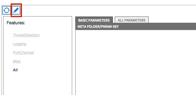
The Edit Cluster Parameters window appears. Click PortChannel in order to limit the scope of the option. Expand the Port Channel Member folder and complete the Configuration Options. Here is an explanation of each option:
- Channel Group ID – In the Value field, enter the PC ID that you wish to assign to the interfaces on the ASA (1 through 48 are supported).
- Interface – In the Value field, enter the interface on the ASA that you wish to assign to the channel group.
Repeat this process for each interface that you wish to assign:

Once complete, you should see a port-channel creation on the ASA in the System context. In order to verify this, access the System context and enter the show port-channel summary command:
ciscoasa#
show port-channel summary
Flags:  D - down        P - bundled in port-channel
        I - stand-alone s - suspended
        H - Hot-standby (LACP only)
        U - in use      N - not in use, no aggregation/nameif
        M - not in use, no aggregation due to minimum links not met
        w - waiting to be aggregated
Number of channel-groups in use: 2
Group  Port-channel  Protocol  Span-cluster  Ports
------+-------------+---------+------------+-----------------------
27 Po27(N) LACP No Gi0/4(P) Gi0/5(P)[an error occurred while processing this directive]
Add the User Context as an L4-L7 Device
You must register the User context as an L4-L7 device in the fabric. Navigate to Tenant > L4-L7 Services > L4-L7 Devices, right-click and select Create an L4-L7 Device, and then complete these steps:
- Click the Managed check box in the General area, if it is not already enabled.
- Enter the device Name.
- Select the Service Type from the drop-down menu.
- Choose the Device Type.
- Select the Physical Domain from the drop-down menu.
- Choose the Mode.
- Select CISCO-ASA-1.2 from the Device Package drop-down menu.
- Select the ASA Model from the drop-down menu.
- Choose an APIC to Device Management Connectivity option in the Connectivity area.
- Choose the Function Type (GoThrough is Transparent mode and GoTo is Routed mode).
- Enter your Username and Password in the Credentials area.
- Enter the IP address of the User context into the Management IP Address field (along with the Port) in the Device 1 area.
- Create a physical interface, give it a name, choose the Interface Policy Group that the ASA uses, and then select Provider and consumer.
- Enter the Management IP Address of the Admin context (along with the Port) in the Cluster area. Create two cluster interfaces (one consumer and one provider) that point to the same port-channel.

Note: You can finish you use of the wizard at this time. You do not need to configure any of the failover information.
- Verify that the device is stable and that there are no faults:

Add the NetScaler 1000V as an L4-L7 Device
The second node in this configuration example is a NetScaler 1000V. The NetScaler provides load balancing functionality to the connected servers. You must register this device with the APIC as well. Navigate to Tenant > L4-L7 Services > L4-L7 Devices, right-click and select Create an L4-L7 Device, and then complete these steps:
- Click the Managed check box in the General area, if it is not already enabled.
- Enter the device Name.
- Select the Service Type from the drop-down menu (NetScaler is an ADC, or Application Delivery Controller).
- Choose the Device Type.
- Select the VMM Domain (if Virtual) from the drop-down menu.
- Choose the Mode.
- Select Cisco-NetScaler1KV-1.0 from the Device Package drop-down menu.
- Select the Model from the drop-down menu (Virtual Appliance is the NetScaler-VPX)
- Choose an APIC to Device Management Connectivity option in the Connectivity area.
- Enter your Username and Password in the Credentials area.
- Enter the IP address of the Admin context into the Management IP Address field (along with the Port) in the Device 1 area. Choose the VM (if Virtual).
- Create an external interface in the Device Interfaces area, and choose an unused network adapter.
Note: Network Adapter 1 is used for management purposes, so do not use it.
- Create an internal interface in the Device Interfaces area, and choose an unused network adapter.
- Enter the same information that you used for the Device 1 area into the Cluster area. Create two cluster interfaces (one consumer and one provider).

- Verify that the device is stable and that there are no faults:

Create the Service Graph Template
Now that the devices are registered, you can create a Service Graph Template. Navigate to Tenant > L4-L7 Services > L4-L7 Service Graph Templates > Create L4-L7 Service Graph Template, and complete these steps:
- Enter a name in the Graph Name field.
- Drag-and-drop the devices from the Device Clusters area in the order that they should be deployed. Enter a name for each.
- Choose the function Profile for each device. For the NetScaler, this example uses Two-Arm (or Inline mode).
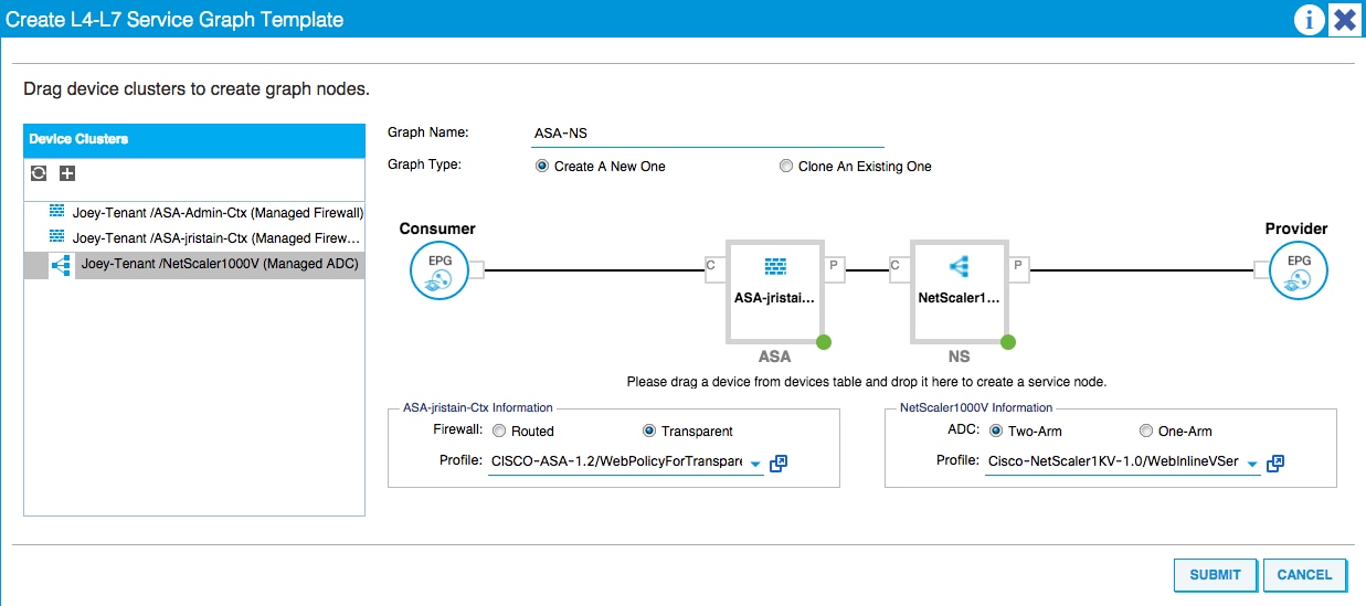
Deploy the Service Graph Template
After the template is created, you can deploy it to the devices. Navigate to Tenant > L4-L7 Services > L4-L7 Service Graph Templates > Service Graph Template > Apply Service Graph Template.
On the Contract tab, complete these steps:
- Select the consumer EPG from the Consumer EPG / External Network drop-down menu.
- Select the provider EPG from the Provider EPG / External Network drop-down menu.
- Create a new contract, or choose one that already exists, in the Contract Information area.
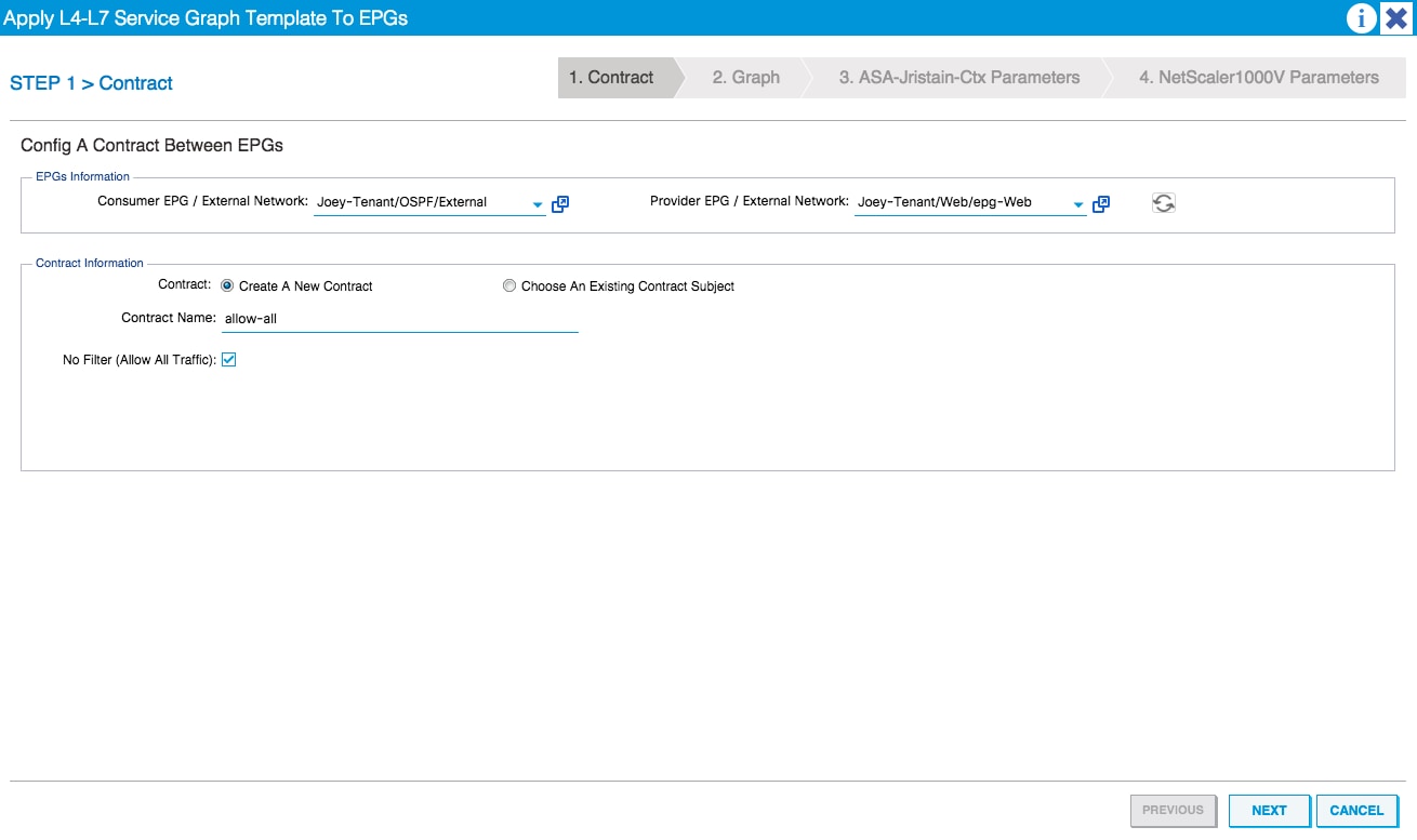
On the Graph tab, complete these steps:
- Select the BD for the ASA external interface from the BD drop-down menu.
- Select the BD For the ASA internal interface from the BD drop-down menu.
- Select the BD for the NetScaler external interface from the BD drop-down menu.
- Select the BD for the NetScaler internal interface from the BD drop-down menu.
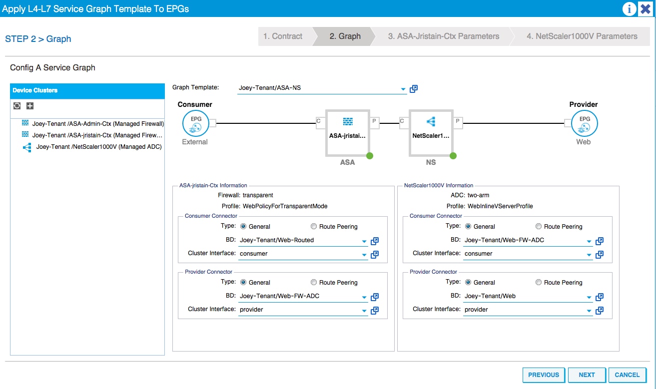
On the ASA Parameters tab, enter the desired parameters. None of the parameters on this tab are required.
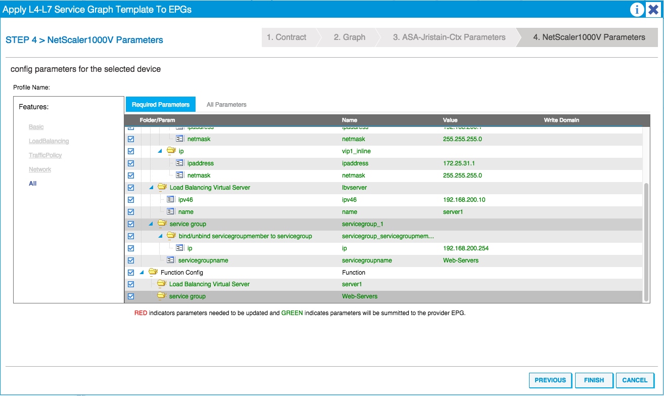
On the NetScaler Parameters tab, enter the NetScaler configuration via the wizard:
Verify
There is currently no verification procedure available for this configuration.
Troubleshoot
This section provides information that you can use in order to troubleshoot your configuration.
Known Faults
Here are two known faults that are related to the configurations that are described in this document:
- Script Warning: Either the cable is incorrect or not plugged into the interface connector:
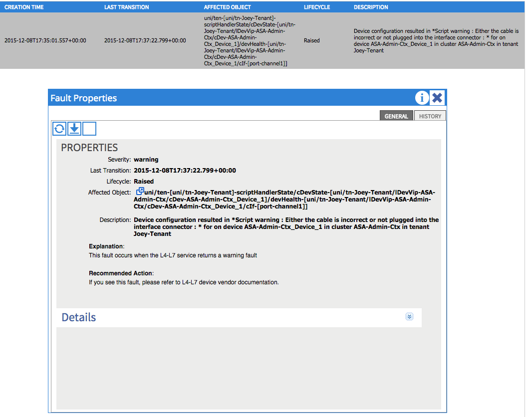
In order to resolve this issue, ensure that the port-channel parameters are configured and that the port-channel is up on the ASA. Refer to the Configure the Port-Channel Parameters section of this document for information about how to verify this.
If the interface is up, but you still see these faults, it is likely due to Cisco bug ID CSCuw56882. This bug is fixed in the 1.2.3 Device Package support for the 1.2(x) ACI software release. The device packages can be downloaded here. - Major Script Error: Connection error : 401 Client Error: Unauthorized:
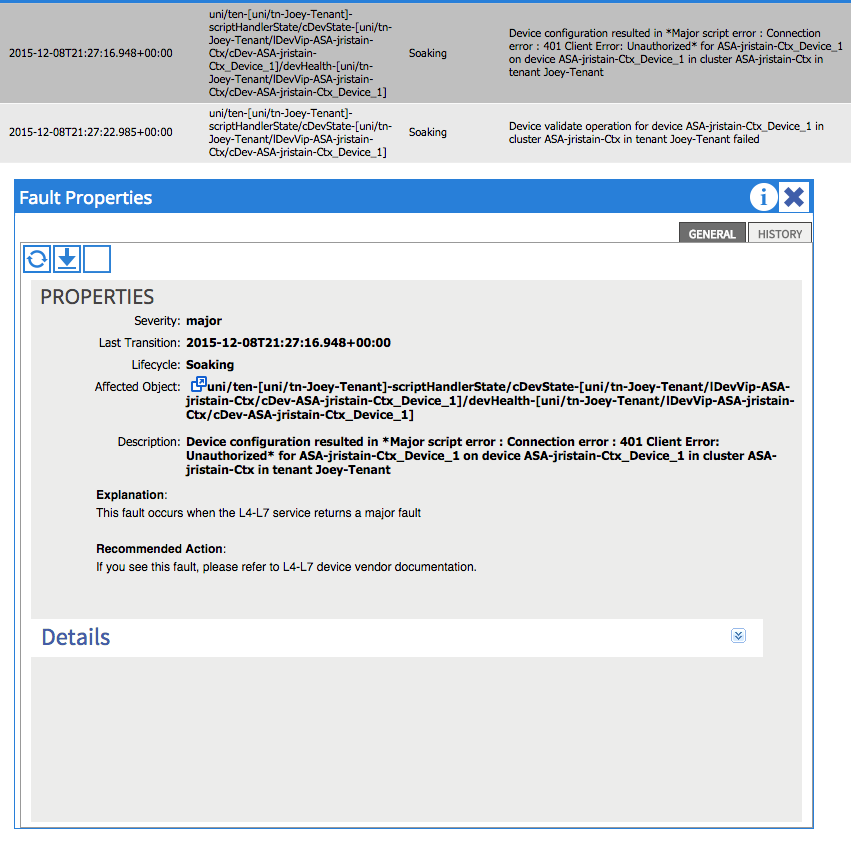
In order to resolve this issue, ensure that the proper credentials are provisioned on the devices and configured correctly in the APIC.
Contributed by Cisco Engineers
- Joseph RistainoCisco TAC Engineer
Contact Cisco
- Open a Support Case

- (Requires a Cisco Service Contract)
 Feedback