ACI Remote Leaf Discovery and Configuration
Available Languages
Download Options
Bias-Free Language
The documentation set for this product strives to use bias-free language. For the purposes of this documentation set, bias-free is defined as language that does not imply discrimination based on age, disability, gender, racial identity, ethnic identity, sexual orientation, socioeconomic status, and intersectionality. Exceptions may be present in the documentation due to language that is hardcoded in the user interfaces of the product software, language used based on RFP documentation, or language that is used by a referenced third-party product. Learn more about how Cisco is using Inclusive Language.
Contents
Introduction
This document describes the steps to discover and configure a Remote Leaf (RLEAF) in an existing Application Centric Infrastructure (ACI) fabric with the Application Policy Infrastructure Controller (APIC) GUI.
Background Information
The ACI remote leaf switch deployment helps the customers to extend ACI fabric (ACI services and APIC management) to remote datacenters where there is no local spine switch or APIC attached. The remote leaf switches are added to an existing pod in the fabric over the Wide Area Network (WAN). All policies deployed in the main datacenter are deployed in the remote switches, which behave like local leaf switches that belong to the fabric. In the remote leaf topology, all unicast traffic is transmitted through VXLAN over Layer 3. Layer 2 Broadcast, Unknown unicast, and Multicast (BUM) traffic are sent with Head End Replication (HER) tunnels without the use of Multicast. All local traffic on the remote site is switched directly between endpoints, whether physical or virtual. Any traffic that requires the use of the spine proxy is forwarded to the main fabric. Just like a local leaf, the remote leaf can be used to connect virtual servers, physical servers, and containers. Traffic to the endpoints connected to the remote leaf is locally forwarded through remote leaf switches.
Prerequisites
Requirements
Cisco recommends that you have knowledge of these topics:
- ACI Fabric
- ACI GUI
- ACI Leaf and Spine Switch CLI
- NXoS switch CLI
Components Used
The information in this document is based on these software and hardware versions:
- APIC Version 3.1(2q)
- Spine LC N9K-X9732C-EX
- Leaf N9K-X9732C-EX
- IP Network(IPN) - Nexus 7000, N7K-SUP2E, N7K-F348XP-25
The information in this document was created from the devices in a specific lab environment. All of the devices used in this document started with a cleared (default) configuration. If your network is live, ensure that you understand the potential impact of any command.
Background Information
The remote leaf solution is supported by ACI 3.1(1) release. The list of hardware that supports the Remote leaf solutions as of the date this document was written is listed in the table.
|
Spine/Leaf |
Model |
|---|---|
|
Fixed Spine |
N9364C |
|
Modular Spine LC |
N9732C-EX N9736C-FX |
|
Leaf |
N93180YC-EX N93180YC-FX N93108TC-EX N93108TC-FX N93180LC-EX N9348GC-FXP N9336C-FX2 |
Configure
Network Diagram
This network diagram depicts the topology used in this example.

Configurations
This document mainly focuses on the ACI side of configuration for remote leaf deployment and it doesn't cover full details of the WAN side configuration of the IPN switch. However, a few important configurations from IPN are listed here for reference.
Remote WAN Configuration (ACI Main Fabric Side)
These are the configurations used in the IPN device connected to the ACI Spine(s) in the main fabric:
vrf context RLEAF
  description VRF created for remote-leaf lab


router ospf 1

  vrf RLEAF
    router-id 172.16.191.191
    area 0.0.0.1 nssa


# In this example same IPN router is used to connect to RLEAF and SPINE


interface loopback191
  vrf member RLEAF
  ip address 172.16.191.191/32
Interface specific configurations on the IPN that connects to the Spine.
|
Towards Spine-601 |
Towards Spine-501 |
|
interface Ethernet3/38 mtu 9150 no shutdown interface Ethernet3/38.4 description link to spine601 mtu 9150 encapsulation dot1Q 4 vrf member RLEAF ip address 10.10.19.10/24 ip ospf network point-to-point ip router ospf 1 area 0.0.0.1 no shutdown |
interface Ethernet3/39 mtu 9150 no shutdown interface Ethernet3/39.4 description link to spine501 mtu 9150 encapsulation dot1Q 4 vrf member RLEAF ip address 10.10.20.10/24 ip ospf network point-to-point ip router ospf 1 area 0.0.0.1 no shutdown |
Remote WAN Configuration (RLEAF side)
These are the configurations used in the IPN device connected to the remote leaf:
|
vrf context RLEAF router ospf 1 vrf RLEAF # In this example same IPN router is used to connect to RLEAF and SPINE interface loopback191 |
Interface specific configurations on the IPN that connects to the RLEAF:
|
Towards RLEAF-204 |
Towards RLEAF-203 |
|
interface Ethernet3/34 mtu 9150 no shutdown interface Ethernet3/34.4 description link to rleaf204 mtu 915 encapsulation dot1Q 4 ip access-group 100 in vrf member RLEAF ip address 10.10.21.10/24 ip ospf network point-to-point ip router ospf 1 area 0.0.0.1 ip dhcp relay address 10.0.0.1 ip dhcp relay address 10.0.0.2 ip dhcp relay address 10.0.0.3 no shutdown |
interface Ethernet3/35 mtu 9150 no shutdown interface Ethernet3/35.4 description link to rleaf203 mtu 9150 encapsulation dot1Q 4 ip access-group 100 in vrf member RLEAF ip address 10.10.22.10/24 ip ospf network point-to-point ip router ospf 1 area 0.0.0.1 ip dhcp relay address 10.0.0.1 ip dhcp relay address 10.0.0.2 ip dhcp relay address 10.0.0.3 no shutdown |
Note: Ensure the dhcp-relay IP is configured with the APIC fabric IP address under the interface connected to the remote-leaf. This is required for the remote leaf to obtain the bootstrap files from APIC. In this example, 10.0.0.1, 10.0.0.2, 10.0.0.3 are the APIC TEP IP address. The remote-leaf sends DHCP DISCOVER towards the WAN to get the IP address of the subinterface connected to the WAN Router. WAN Router relays the DHCP DISCOVER message from Remote Leaf to the APICs in POD.
ACI Configuration Step 1. Configure Pod Fabric Setup Policy
1. Navigate to Fabric > Inventory > Pod Fabric Setup Policy.
2. Double click to open Fabric Setup Policy for existing Pod.
3. Add (+) Remote Pool, provide a Remote ID (in this example: 11) and Remote Pool (in this example: 172.17.0.0/20) and click Submit. The image snippet may show a different IP addressing scheme.
Note: The remote leaf TEP pool subnet must not overlap with the main fabric TEP pool subnet. The subnet used must be /24 or lower.

ACI Configuration Step 2. Configure Routed Outside from Spine to IPN
1. Navigate to Tenant > Infra > External Routed Networks.
2. Right-click andcreate Routed Outside.
3. Configure OSPF Routed Outside for Spine to IPN.
4. Use OSPF as a routing protocol.
5. Use overlay-1 as VRF.
In this example, the remote leaf is attached to a single pod fabric. So, "Enable remote leaf with Multipod" is not selected. If you use remote leaf with a multipod fabric, this option must be checked.
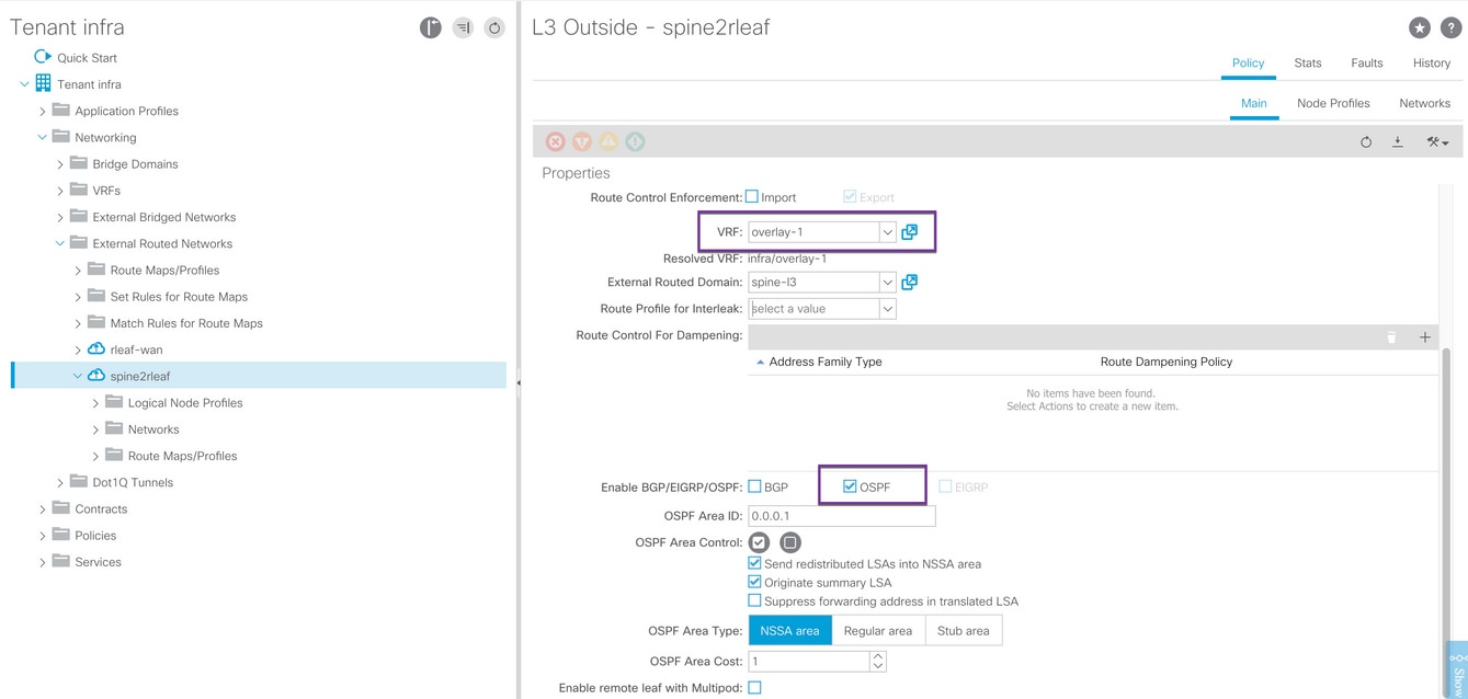
Configure the Node profile for each spine (in this example node-501 & node-601) connected to IPN. The example for node-501 is shown here. Follow the same steps for node-601. Image snippets may show different IP addressing schemes.

Configure interface profile for IPN connection.
Note: Ensure to use encap vlan-4 for remote leaf integration with a single pod.
Example for path-501/pathep-[eth1/9].

Example for path-601/pathep-[eth2/9].

Configure L3Out Network(External EPG) for IPN.
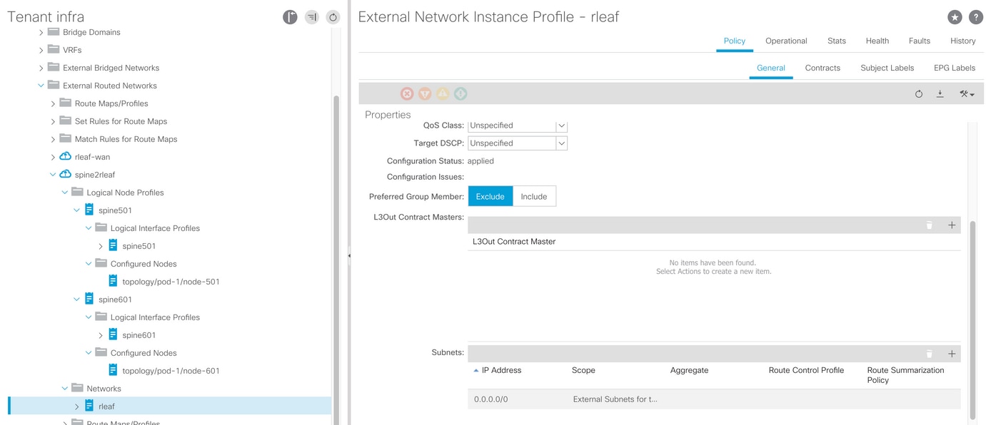
Now that you've configured OSPF L3Out from Spine (node-501 & node-601) to the IPN device. The OSPF adjacency should be up and routes are exchanged provided the OSPF on the IPN is configured correctly. So, check the OSPF neighbourship from Spine to IPN device.
From Spine:
spine501# show ip ospf neighbors vrf overlay-1
OSPF Process ID default VRF overlay-1
Total number of neighbors: 1
Neighbor ID     Pri State            Up Time  Address         Interface
172.16.191.191  1 FULL/ -          00:00:36 10.10.20.10     Eth1/9.9
spine501#
spine601# show ip ospf neighbors vrf overlay-1
OSPF Process ID default VRF overlay-1
Total number of neighbors: 1
Neighbor ID     Pri State            Up Time  Address         Interface
172.16.191.191  1 FULL/ -          00:00:39 10.10.19.10     Eth2/9.9
spine601#
From IPN:
SPINE-IPN# show ip ospf neighbors vrf RLEAF
OSPF Process ID 1 VRF RLEAF
Total number of neighbors: 2
Neighbor ID     Pri State            Up Time  Address         Interface
172.16.60.60       1 FULL/ -          00:00:06 10.10.19.11     Eth3/38.4
172.16.50.50       1 FULL/ -          00:00:17 10.10.20.11     Eth3/39.4
SPINE-IPN#
Now you have OSPF neighborship between Spine and IPN and you can see that the route to ACI fabric pod infra network is learned at IPN over the OSPF.
SPINE-IPN# show ip route vrf RLEAF
IP Route Table for VRF "RLEAF"
'*' denotes best ucast next-hop
'**' denotes best mcast next-hop
'[x/y]' denotes [preference/metric]
'%' in via output denotes VRF

10.0.0.0/16, ubest/mbest: 2/0
    *via 10.10.19.11, Eth3/38.4, [110/20], 00:01:21, ospf-1, nssa type-2
    *via 10.10.20.11, Eth3/39.4, [110/20], 00:01:21, ospf-1, nssa type-2
< snip >
SPINE-IPN#
ACI Configuration Step 3. Discover the Remote Leaf(s)
At this stage, the fabric is ready to discover a remote leaf connected to IPN across the WAN. Ensure that the IPN connected to the RLEAF has the route to the ACI pod infra network over the WAN network.
RLEAF-IPN# show lldp neighbors
Capability codes:
  (R) Router, (B) Bridge, (T) Telephone, (C) DOCSIS Cable Device
  (W) WLAN Access Point, (P) Repeater, (S) Station, (O) Other
Device ID            Local Intf      Hold-time  Capability  Port ID
switch               Eth3/34         120        BR           Eth1/54
switch               Eth3/35         120        BR           Eth1/54
Total entries displayed: 2
RLEAF-IPN#

RLEAF-IPN# show ip route vrf RLEAF
IP Route Table for VRF "RLEAF"
'*' denotes best ucast next-hop
'**' denotes best mcast next-hop
'[x/y]' denotes [preference/metric]
'%<string>' in via output denotes VRF <string>

10.0.0.0/16, ubest/mbest: 2/0
    *via 10.10.19.11, Eth3/38.4, [110/20], 00:01:21, ospf-1, nssa type-2
    *via 10.10.20.11, Eth3/39.4, [110/20], 00:01:21, ospf-1, nssa type-2

< snip >
Review the IPN connected to the remote leaf and ensure that the APIC fabric IP address is configured as DHCP relay.
RLEAF-IPN# show ip dhcp relay
< snip >

Helper addresses are configured on the following interfaces:
 Interface        Relay Address     VRF Name
 -------------    -------------     --------
 Ethernet3/34.4    10.0.0.1
 Ethernet3/34.4    10.0.0.2
 Ethernet3/34.4    10.0.0.3
 Ethernet3/35.4    10.0.0.1
 Ethernet3/35.4    10.0.0.2
 Ethernet3/35.4    10.0.0.3
RLEAF-IPN#
Navigate to Inventory > Fabric Membership in ACI GUI and check for thenew switches discovered.

Register the newly discovered leaf to the existing fabric:
1. Identify the new leaf based on the serial number.
2. Right-click on the newly discovered leaf and click Register.
3. Provide the right Pod ID and Node ID.
4. Select the RL TEP POOL.
5. Provide a Node Name.
6. Check and Confirm the Role is selected as remote leaf.
7. Click Update.

Note: Ensure to select the correct RL TEP Pool you configured in Step 1. Also, check and confirm the Role is selected as a remote leaf automatically when you select the RL TEP POOL from the dropdown.
Now you can see the node type is identified as "remote leaf" and status as "Discovering". The node hasn't got a fabric IP address yet.

ACI Configuration Step 4. Configure Routed OutSide from RLEAF to IPN
1. Navigate to Tenant > Infra > External Routed Networks and create Routed Outside.
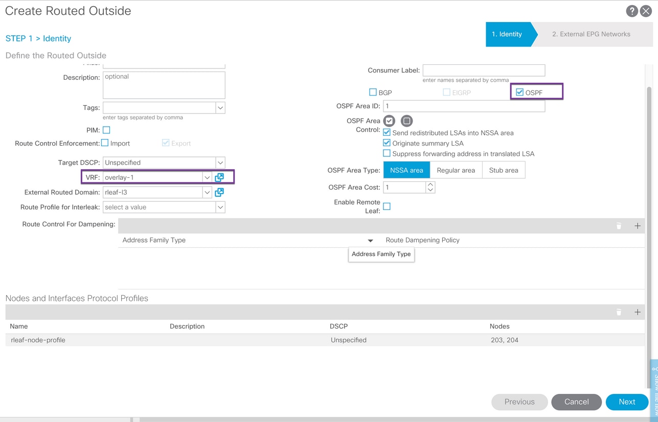
2. Create RLEAF node profiles for node-203 and 204.
Now, you can select the rleaf-203 (Node-203) and rleaf-204(Node-204) from the Node ID dropdown list as they are now discovered in the fabric.
RLEAF 203 Node Profile:
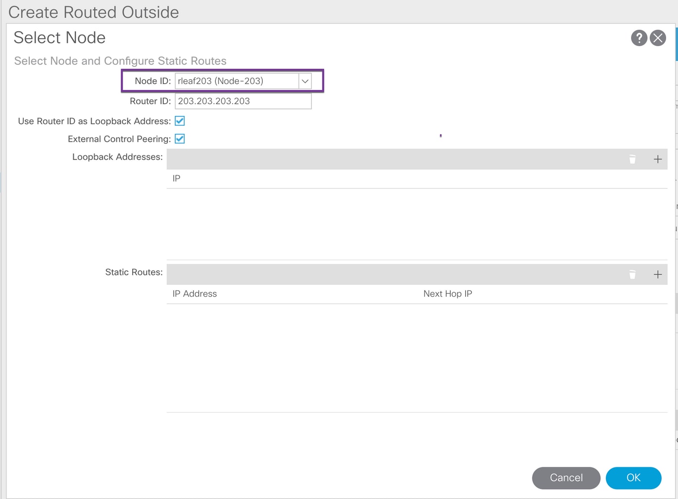
RLEAF 204 Node profile:

Create RLEAF interface profile for node-203 & node-204:
Note: You can not see the Noderleaf-203 (Node-203)or rleaf-204 (Node-204) from theNode dropdown list as the RLEAF203 or RLEAF204 is not registered. So, manually enter the path in Node & Path fields as shown in the image.
Create the interface profile for node-203. Manually enter Node and Path fields as shown.
Node: topology/pod-1/node-203

Path: topology/pod-1/paths-203/pathep-[eth1/54]
Create the interface profile for node-204. Manually enter Node and Path fields as shown.
Node: topology/pod-1/node-204

Path: topology/pod-1/paths-204/pathep-[eth1/54]
Create the L3Out External Network (External EPG):

ACI Configuration Step 5. Create Fabric External Connection Policy
1. Navigate to Tenant > Infra > Policies > Protocol > Fabric Ext Connection Policy > Fabric External Connection Policy and create Intrasite/Intersite Profile.
2. Add Fabric External Routing Profile with an external network of RLEAF203 and RLEAF204 connected to the WAN router (IPN).
3. In this case, those are 10.10.22.0/24 and 10.10.21.0/24 respectively.

ACI Configuration Step 6. Register Remote Leaf to ACI Fabric Pod
Then the remote leaf obtains the fabric IP address from the APIC TEP pool.

Wait for a while to get the remote-leaf to active status. Now, you can see that the remote leaf rleaf-203 and rleaf-204 are registered to ACI fabric.

apic3# acidiag fnvread
      ID   Pod ID                 Name    Serial Number         IP Address    Role        State   LastUpdMsgId
--------------------------------------------------------------------------------------------------------------
     101        1              leaf101      SAL1946SWJM     10.0.232.64/32    leaf         active   0
     102        1              leaf102      SAL1946SWNS     10.0.232.73/32    leaf         active   0
     103        1              leaf103      SAL1946SWNU     10.0.232.69/32    leaf         active   0
     104        1              leaf104      SAL1946SWNT       10.0.8.64/32    leaf         active   0
     201        1              leaf201      FDO21031WXP     10.0.232.72/32    leaf         active   0
     202        1              leaf202      FDO20331BFQ     10.0.232.68/32    leaf         active   0
     203        1             rleaf203      FDO22080JDA      172.17.3.128/32    leaf         active   0
     204        1             rleaf204      FDO220810B0      172.17.7.128/32    leaf         active   0
     501        1             spine501      FOX1949GHHM     10.0.232.66/32    spine        active   0
     601        1             spine601      FOX1948G9EA     10.0.232.65/32    spine        active   0

Total 10 nodes

apic3#
Now, you can see the OSPF neighbourship between remote leaf and IPN.
From RLEAF 203:
rleaf203# show ip ospf neighbors vrf overlay-1
 OSPF Process ID default VRF overlay-1
 Total number of neighbors: 1
 Neighbor ID     Pri State            Up Time  Address         Interface
 172.16.191.191  1 FULL/ -          00:24:57 10.10.22.10     Eth1/54.6
rleaf203#

rleaf203# show ip route vrf overlay-1
IP Route Table for VRF "overlay-1"
'*' denotes best ucast next-hop
'**' denotes best mcast next-hop
'[x/y]' denotes [preference/metric]
'%<string>' in via output denotes VRF <string>

10.0.0.0/16, ubest/mbest: 1/0
    *via 10.10.22.10, eth1/54.6, [110/20], 00:30:24, ospf-default, nssa type-2
10.0.0.1/32, ubest/mbest: 1/0
    *via 10.10.22.10, eth1/54.6, [110/20], 00:30:24, ospf-default, nssa type-2

< snip >
From RLEAF 204:
rleaf204# show ip ospf neighbors vrf overlay-1
 OSPF Process ID default VRF overlay-1
 Total number of neighbors: 1
 Neighbor ID     Pri State            Up Time  Address         Interface
 172.16.191.191  1 FULL/ -          00:25:36 10.10.21.10     Eth1/54.6
rleaf204#

rleaf204# show ip route vrf overlay-1
IP Route Table for VRF "overlay-1"
'*' denotes best ucast next-hop
'**' denotes best mcast next-hop
'[x/y]' denotes [preference/metric]
'%<string>' in via output denotes VRF <string>

10.0.0.0/16, ubest/mbest: 1/0
    *via 10.10.21.10, eth1/54.6, [110/20], 00:31:37, ospf-default, nssa type-2
10.0.0.1/32, ubest/mbest: 1/0
    *via 10.10.21.10, eth1/54.6, [110/20], 00:31:37, ospf-default, nssa type-2

< snip >
From IPN:
RLEAF-IPN# show ip ospf neighbors vrf RLEAF
 OSPF Process ID 1 VRF RLEAF
 Total number of neighbors: 4
 Neighbor ID     Pri State            Up Time  Address         Interface
 172.16.204.204  1 FULL/ -          00:26:03 10.10.21.11     Eth3/34.4
 172.16.203.203   1 FULL/ -          00:26:03 10.10.22.11     Eth3/35.4
RLEAF-IPN#
ACI Configuration Step 7. QoS Configuration for Remote Leaf
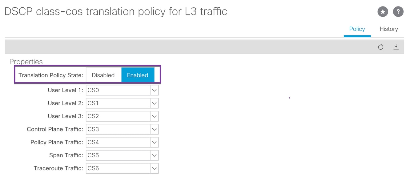
It is required to classify ACI fabric classes (QoS Levels) to a DSCP value within IPN. To achieve this requirement, ACI Fabric should be enabled with DSCP class-cos translation policy for L3 traffic. Use this configuration to map ACI QOS levels and default classes to DSCP values in IPN.
Navigate to Tenant > Infra > Policies > DSCP class-cos translation policy for L3 traffic as shown in the image.
ACI Configuration Step 8 (Optional). Create Virtual Port-Channel (vPC) Explicit Protection Group with Remote Leaf
Since the remote leaf switches are registered to ACI fabric, you can create vPC Explicit Protection Group with a remote leaf. Navigate to Fabric > Access Policies > Switch Policies > Policies > Virtual Port Channel Default and create Explicit VPC Protection Groups (+). Image snippets show different IP addressing schemes.

rleaf203# show system internal epm vpc
Local TEP IP                  : 172.17.3.128
Peer TEP IP                   : 172.17.7.129
vPC configured                : Yes
vPC VIP                       : 172.17.3.130
MCT link status               : Up
Local vPC version bitmap      : 0x7
Peer vPC version bitmap       : 0x7
Negotiated vPC version        : 3
Peer advertisement received   : Yes
Tunnel to vPC peer            : Up

vPC# 343
if : port-channel1, if index : 0x16000000
local vPC state : MCEC_STATE_UP, peer vPC state : MCEC_STATE_UP
current link state : LOCAL_UP_PEER_UP
vPC fast conv : Off
rleaf203#
Verify
RLeaf TEP Review
Remote leaf Data-Plane Tunnel End Point (RL-DP-PTEP) - This IP address is assigned to each Remote leaf switch from the TEP pool that is allocated to the Remote Location. VXLAN packets from a Remote leaf node are originated with this TEP as a source IP address when the Remote leaf nodes are not part of a vPC domain.
Remote Leaf vPC Tunnel End Point (RL-vPC) - This is an anycast IP address assigned to the vPC pair of Remote leaf nodes from the TEP pool that is allocated to the Remote Location. All the VXLAN packets sourced from both Remote leaf switches originated from this TEP address if the Remote leaf switches are part of a vPC domain.
rleaf203# show ip int vrf overlay-1
IP Interface Status for VRF "overlay-1"
eth1/54.6, Interface status: protocol-up/link-up/admin-up, iod: 64, mode: external
  IP address: 10.10.22.11, IP subnet: 10.10.22.0/24
  IP broadcast address: 255.255.255.255
  IP primary address route-preference: 1, tag: 0
lo0, Interface status: protocol-up/link-up/admin-up, iod: 4, mode: ptep
  IP address: 172.17.3.128, IP subnet: 172.17.3.128/32
  IP broadcast address: 255.255.255.255
  IP primary address route-preference: 1, tag: 0
lo1, Interface status: protocol-up/link-up/admin-up, iod: 65, mode: unspecified
  IP address: 172.16.203.203, IP subnet: 172.16.203.203/32
  IP broadcast address: 255.255.255.255
  IP primary address route-preference: 1, tag: 0
lo2, Interface status: protocol-up/link-up/admin-up, iod: 72, mode: vpc
  IP address: 172.17.3.130, IP subnet: 172.17.3.130/32
  IP broadcast address: 255.255.255.255
  IP primary address route-preference: 1, tag: 0
lo3, Interface status: protocol-up/link-up/admin-up, iod: 75, mode: dp-ptep
  IP address: 172.17.3.129, IP subnet: 172.17.3.129/32
  IP broadcast address: 255.255.255.255
  IP primary address route-preference: 1, tag: 0
lo1023, Interface status: protocol-up/link-up/admin-up, iod: 66, mode: ftep
  IP address: 172.17.0.32, IP subnet: 172.17.0.32/32
  IP broadcast address: 255.255.255.255
  IP primary address route-preference: 1, tag: 0

rleaf203#
rleaf204# show ip int vrf overlay-1
IP Interface Status for VRF "overlay-1"
eth1/54.6, Interface status: protocol-up/link-up/admin-up, iod: 64, mode: external
  IP address: 10.10.21.11, IP subnet: 10.10.21.0/24
  IP broadcast address: 255.255.255.255
  IP primary address route-preference: 1, tag: 0
lo0, Interface status: protocol-up/link-up/admin-up, iod: 4, mode: ptep
  IP address: 172.17.7.128, IP subnet: 172.17.7.128/32
  IP broadcast address: 255.255.255.255
  IP primary address route-preference: 1, tag: 0
lo1, Interface status: protocol-up/link-up/admin-up, iod: 65, mode: unspecified
  IP address: 172.16.204.204, IP subnet: 172.16.204.204/32
  IP broadcast address: 255.255.255.255
  IP primary address route-preference: 1, tag: 0
lo2, Interface status: protocol-up/link-up/admin-up, iod: 71, mode: dp-ptep
  IP address: 172.17.7.129, IP subnet: 172.17.7.129/32
  IP broadcast address: 255.255.255.255
  IP primary address route-preference: 1, tag: 0
lo9, Interface status: protocol-up/link-up/admin-up, iod: 81, mode: vpc
  IP address: 172.17.3.130, IP subnet: 172.17.3.130/32
  IP broadcast address: 255.255.255.255
  IP primary address route-preference: 1, tag: 0
lo1023, Interface status: protocol-up/link-up/admin-up, iod: 66, mode: ftep
  IP address: 172.17.0.32, IP subnet: 172.17.0.32/32
  IP broadcast address: 255.255.255.255
  IP primary address route-preference: 1, tag: 0

rleaf204#
Spine TEP Review
Remote leaf Unicast Tunnel End Point (RL-UCAST) – This is an anycast IP address part of the local TEP pool automatically assigned to all the spines to which the Remote leaf switches are being associated. When unicast packets are sent from endpoints connected to the RLEAF nodes to the ACI main Pod, VXLAN encapsulated packets are sent with the destination as RL-Ucast-TEP address and source as RL-DP-TEP or RL-vPC. Any Spine in the ACI main DC Pod can hence receive the traffic, decapsulate it, perform the required L2 or L3 lookup and finally re-encapsulate it and forward it to the final destination.
Remote leaf Unicast Multicast Tunnel End Point (RL-MCAST-HREP) - This is another anycast IP address part of the local TEP pool automatically assigned to all the spines to which the Remote leaf switches are being associated. When BUM (Layer 2 Broadcast, Unknown Unicast, or Multicast) traffic is generated by an endpoint connected to the Remote leaf nodes, packets are VXLAN encapsulated by the RLEAF node and sent with the destination as RL-Mcast-TEP address and source as RL-DP-TEP or RL-vPC Any of the spines in the ACI Pod can receive the BUM traffic and forward it inside the fabric.
spine501# show ip int vrf overlay-1
< snip >
lo12, Interface status: protocol-up/link-up/admin-up, iod: 88, mode: rl-mcast-hrep
  IP address: 10.0.0.37, IP subnet: 10.0.0.37/32
  IP broadcast address: 255.255.255.255
  IP primary address route-preference: 1, tag: 0
lo13, Interface status: protocol-up/link-up/admin-up, iod: 91, mode: rl-ucast
  IP address: 10.0.0.36, IP subnet: 10.0.0.36/32
  IP broadcast address: 255.255.255.255
  IP primary address route-preference: 1, tag: 0
spine501#
spine601# show ip int vrf overlay-1
< snip >
lo11, Interface status: protocol-up/link-up/admin-up, iod: 76, mode: rl-mcast-hrep
  IP address: 10.0.0.37, IP subnet: 10.0.0.37/32
  IP broadcast address: 255.255.255.255
  IP primary address route-preference: 1, tag: 0
lo12, Interface status: protocol-up/link-up/admin-up, iod: 79, mode: rl-ucast
  IP address: 10.0.0.36, IP subnet: 10.0.0.36/32
  IP broadcast address: 255.255.255.255
  IP primary address route-preference: 1, tag: 0

spine601#
Remote Leaf Routable Subnets
If the APICs are reachable via the IPN/ISN/WAN, then the remote subnet is not required for remote leaf nodes to be discovered. This subnet is used to create NAT entries for APICs on the spine switches and to support vPOD. This feature can also be used in conjunction with RL Direct.
F0467 Configuration Failed
If you use the wizard to add a remote leaf to a pod, the wizard does not configure the required access policies listed here and you see the popular F0467 fault message. You need to manually create them.
- Leaf Switch Profile for Remote Leaf nodes and Leaf Selectors
- Leaf Interface Profile for Remote Leaf nodes and Interface Selector for the uplinks
- Access Interface Policy group
F0467 Fault delegate: Configuration failed for uni/tn-infra/out-rl-infra.l3out/instP-ipnInstP node 203 eth1/54 due to Invalid Path Configuration, debug message: invalid-path: Either the EpG is not associated with a domain or the domain does not have this interface assigned to it;

topology/pod-1/node-203/local/svc-policyelem-id-0/uni/epp/rtd-[uni/tn-infra/out-rl-infra.l3out/instP-ipnInstP]/node-203/stpathatt-[eth1/54]/nwissues
Bootstrap Validation
Remote leaves can fail to be discovered due to enabling Bootscript Validation.
Basically with the Bootscript Validation enabled the leaf comes up and learns about the version it should be running via DHCP and it should then download the image from the APICS. The problem though is that for remote with RL direct enabled to work there are specific tcam rules that must be installed on the leaf to allow the natted APIC traffic. Because the bootscript validation is failing these rules and objects aren't getting installed on the RL. However, because those objects/rules aren't installed it can't successfully download the image from the APIC.
If you encounter a situation like this, try to discover the RL with BSV turned off.
Related Information
Revision History
| Revision | Publish Date | Comments |
|---|---|---|
2.0 |
17-May-2022 |
The IP address in text format was changed to use RFC1918 private addresses. OSPF MTU ignore configuration was removed as it was not best practice. |
1.0 |
10-Sep-2018 |
Initial Release |
Contributed by Cisco Engineers
- Abey K GeorgeCisco TAC Engineer
- Ganesh KumarCisco TAC Engineer
Contact Cisco
- Open a Support Case

- (Requires a Cisco Service Contract)
 Feedback