Introduction
This document describes how to troubleshoot Multi-Pod routing issues in an Application Centric Infrastructure (ACI) network.
Background
When you configure an Inter-Pod Network (IPN) (a non-GOLF (Giant Overlay Forwarding) network) in a Multi-Pod setup, it is easy to miss a few steps. This is especially true if Pod 1 was previously configured, but some of the basic steps were still missed. This is a general guildeline/checklist and the examples are not specific to every situation. The goal of this document is to show the technique used to troubleshoot the configuration.
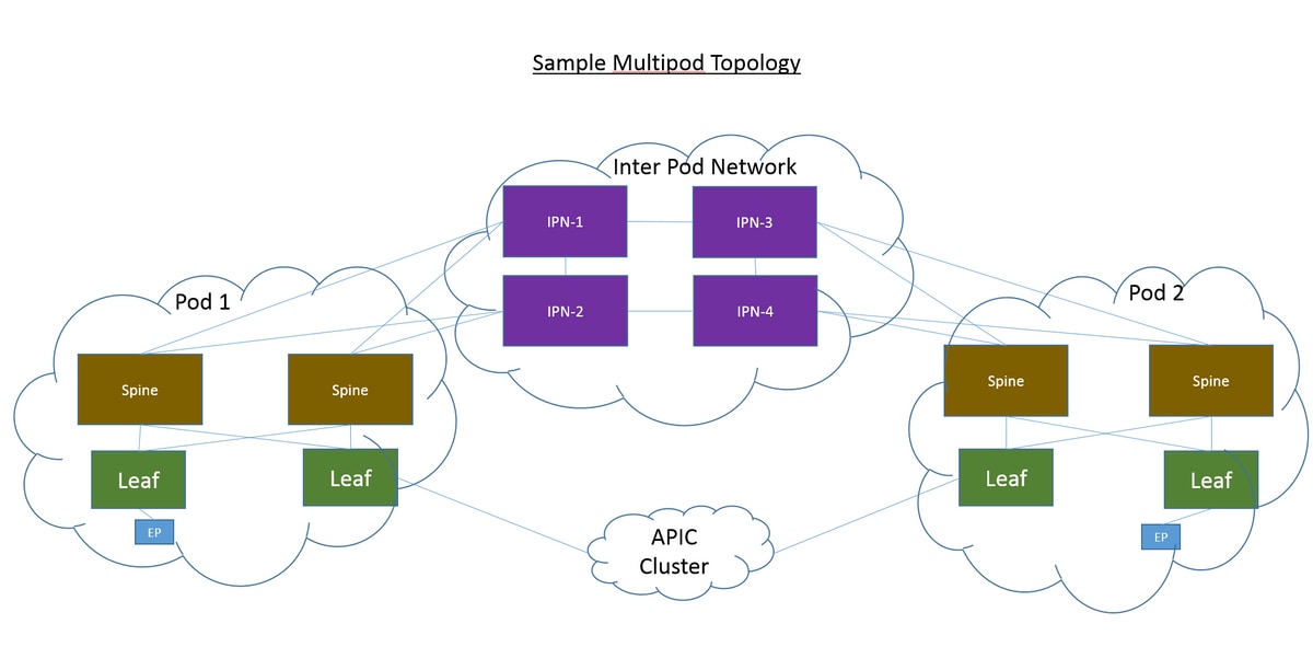
Sample Setup
The source endpoint in Pod 2 is unable to ping the destination in Pod 1 across the IPN, as shown in this image.

Components Used
The information in this document was created from the devices in an ACI lab environment on Version 2.3(1i). All of the devices used in this document started with a cleared (default) configuration. If your network is live, ensure that you understand the potential impact of any command.
Troubleshoot
These steps are common for all designs, inclusive of Multi-Pod.
Step 1. Route Reflector
Verify that the Route Reflectors are configured on both pods.
From the Compute Leaf in Pod 2, enter this command:
show bgp sessions vrf overlay-1
From the Compute/Border Leaf in Pod 1, enter this command:
show bgp sessions vrf overlay-1
Step 2. Bridge Domain to L3out
The Bridge Domain (BD) associated with the source endpoint End Point Group (EPG) must have:
- Unicast routing enabled
- L3out associated with the BD
Step 3. Contracts
The L3out and EPG must have appropriate contracts. If you believe contracts are the problem, Unenforce Virtual Routing and Forwarding (VRF).
In order to check contract drops on any leaf, enter this command:
show logging ip access-list internal packet-log deny | grep <source_ip or destination_ip>
Step 4. IP Route
From the Compute Leaf in Pod 1, you must see the routes for the destination. Likewise, from the Border Leaf in Pod 2, you must see the routes for the source. Enter this command in order to verify the routes:
show ip route <source_ip/destination_ip> vrf <VRF>
Step 5. Endpoint Learning and iping
Check both source and destination learning for each leaf in order to rule out any stale endpoint entries. Trace the endpoint learning to the correct leaf and trace where the ping breaks.
On both Compute Leaf in Pod 2 and Border Leaf in Pod 1, enter these commands:
show endpoint ip <source_ip>
show endpoint ip <destination_ip>

show interface tunnelx
acidiag fnvread

iping -V <VRF> <source_ip> -S <BD_SVI_ip>
iping -V <VRF> <destination_ip> -S <BD_SVI_ip>
Step 6. Address Resolution Protocol
Check the source to see if Address Resolution Protocol (ARP) is resolved for the destination.
Step 7. Embedded Logic Analyzer Module
Trigger the ingress Embedded Logic Analyzer Module (ELAM) for Internet Control Message Protocol (ICMP) (or ARP if needed) on the Compute Leaf in Pod 2.
A general example for the EX switch is:
vsh_lc
deb plat int tah el as 0
trig reset
trig init in 6 o 1
set outer ipv4 src_ip <src_ip> dst_ip <dst_ip>
stat
start
stat
report | egrep SRC|hdr.*_idx|ovector_idx|a.ce_|l3v.ip.*a:|af.*cla|f.epg_|fwd_|vec.op|cap_idx
Trigger the egress ELAM for ICMP (or ARP if needed) on the Border Leaf in Pod 1.
A general example for the EX switch is:
vsh_lc
deb plat int tah el as 0
trig reset
trig init in 7 o 1
set inner ipv4 src_ip <src_ip> dst_ip <dst_ip>
stat
start
stat
report | egrep SRC|hdr.*_idx|ovector_idx|a.ce_|l3v.ip.*a:|af.*cla|f.epg_|fwd_|vec.op|cap_idx
The next steps are specific to Multi-Pod designs.
Step 8. IPN Device Check
From EACH of the IPN devices, complete these steps:
- Collect the route processor (RP) address. Ensure the RP address is the same on all the IPN devices.
show run pim
- Verify that the IPN device with the lowest cost is towards the RP (if phantom RP, then check for secondary RP).
show run interface <loopback0>
- Ensure that all IPNs can ping the RP/secondary RP address.
ping <rp_ip> vrf <VRF>
- Ensure that the routes toward this RP do NOT go toward the spines.
show ip route <rp_ip> vrf <VRF> show lldp neighbors
Step 9. BD Group IP Outer Address
The BD Group IP outer address (GIPo) is the multicast address.
In order to find the BD GIPo from the GUI, navigate to Bridge Domain > Policy > Advanced/Troubleshooting > Multicast Address.
Step 10. mroute
From the ACI Compute Leaf in Pod 2, enter this command in order to verify that the process is pushed:
show ip mroute <BD_GIPO_ip> vrf <VRF>
From the ACI Border Leaf in Pod 1, enter this command in order to verify that the process is pushed:
show ip mroute <BD_GIPO_ip> vrf <VRF>
Related Information
