Troubleshoot ACI Fabric Discovery - Multi-Pod Discovery
Available Languages
Download Options
Bias-Free Language
The documentation set for this product strives to use bias-free language. For the purposes of this documentation set, bias-free is defined as language that does not imply discrimination based on age, disability, gender, racial identity, ethnic identity, sexual orientation, socioeconomic status, and intersectionality. Exceptions may be present in the documentation due to language that is hardcoded in the user interfaces of the product software, language used based on RFP documentation, or language that is used by a referenced third-party product. Learn more about how Cisco is using Inclusive Language.
Contents
Introduction
This document describes steps to understand and troubleshoot ACI Multi-pod Discovery.
Background Information
The material from this document was extracted from the Troubleshooting Cisco Application Centric Infrastructure, Second Edition book, specifically the Fabric Discovery - Multi-pod Discovery chapter.
Multi-Pod Overview
ACI Multi-Pod allows for the deployment of a single APIC cluster to manage multiple ACI networks that are interconnected. Those separate ACI networks are called 'Pods' and each Pod is a regular two or three-tier spine-leaf topology. A single APIC cluster can manage several Pods.
A Multi-Pod design also allows for the extension of ACI fabric policies across Pods that can physically exist in multiple rooms or even across remote datacenter locations. In a Multi-Pod design, any policy defined on the APIC controller cluster is automatically made available to all Pods.
Finally, a Multi-Pod design increases failure domain isolation. In fact, each Pod runs its own instance of COOP, MP-BGP and IS-IS protocol so faults and issues with any of these protocols are contained within that Pod and cannot spread to other Pods.
Please refer to the document "ACI Multi-Pod White Paper" on cisco.com for more information on Multi-Pod design and best practices.
The main elements of a Multi-Pod ACI fabric are the leaf and spine switches, the APIC controllers and the IPN devices.
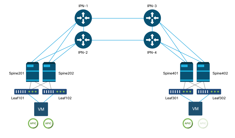
This example dives into the troubleshooting workflow for issues related to setting up an ACI Multi-Pod fabric. The reference topology used for this section is depicted in the picture below:
ACI Multi-Pod reference topology
Troubleshooting workflow
Verify ACI policies
Access Policies
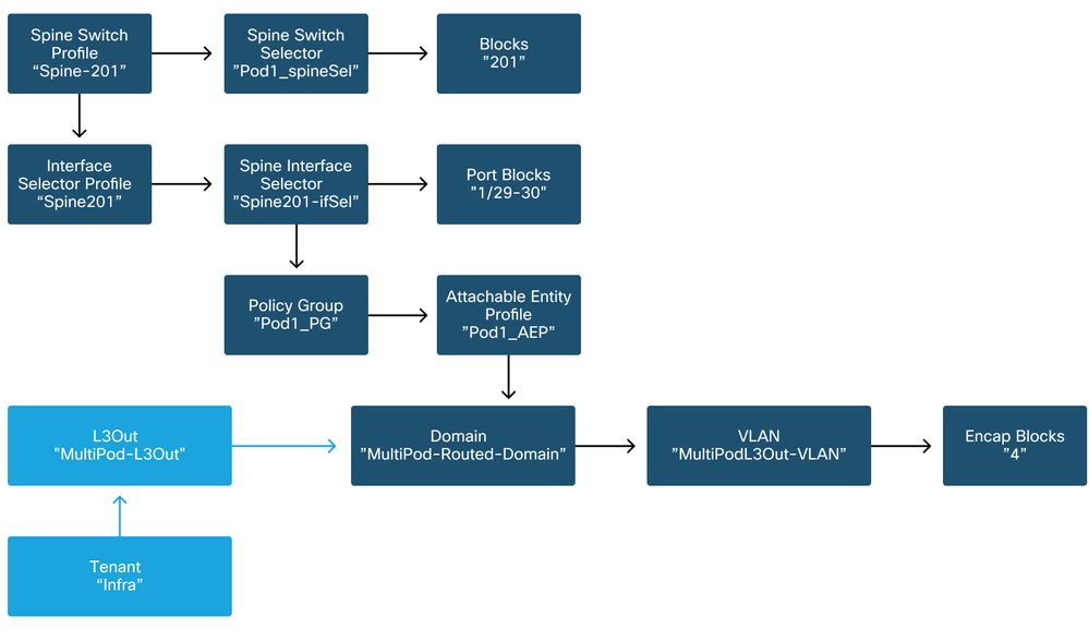
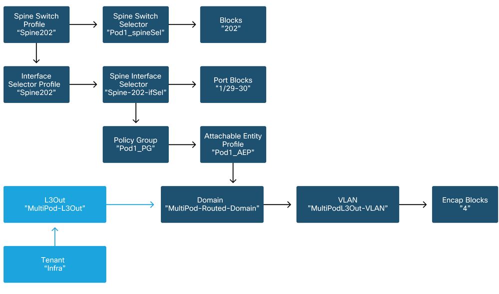
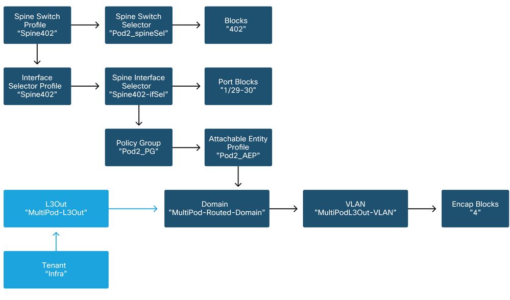
Multi-Pod uses an L3Out in order to connect Pods via the 'infra' tenant. This means the standard set of access policies need to be in place to activate the required Multi-Pod L3Out encapsulation (VLAN-4) on the spine ports facing towards the IPN.
Access Policies can be configured through the 'Add Pod' wizard which should be used to deploy Multi-Pod. After using the wizard, deployed policy can be verified from the APIC GUI. If policies are not properly configured, a fault will appear on the infra tenant and connectivity from spines to the IPN may be not working as expected.
The following schemas can be referenced while verifying access policy definition for the IPN-facing interfaces on the spine nodes:
Spine201
Spine202
Spine401

Spine402
In the infra tenant, the Multi-Pod L3Out should be configured as per the following schema:
Multi-Pod L3Out in infra tenant
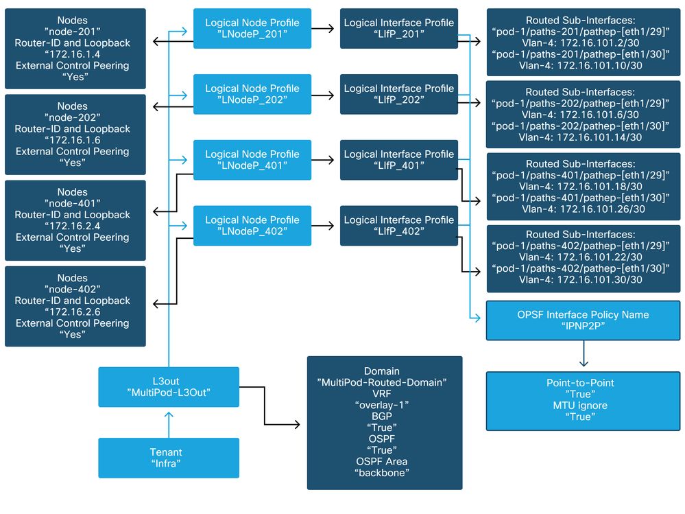
Below is a reference shot of the Multi-Pod L3Out Logical Interface Profile configuration. The router sub-interface definitions should look like the picture below for spine 201
Logical Interface Profile in infra L3Out

For each Pod, there should be a TEP Pool defined as in the picture below. Note that the TEP Pool will be used from APIC controller to provision the IP addresses of the nodes for the overlay-1 VRF.
Pod Fabric Setup Policy

Fabric External Connection Policy default
Verify that in the infra tenant the 'Fabric Ext Policy default' object is defined and configured appropriately. A sample of this configuration is shown in the figures below.
Fabric External Connection Policy default

Dataplane TEP

Fabric External Routing Profile subnets
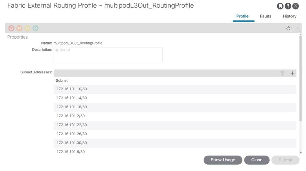
The Fabric External Routing Profile enables the user to verify whether all routed subnets of the IPN defined are on it.
IPN Validation
Multi-Pod relies on an Inter-Pod Network (IPN) which will provide POD-to-POD connectivity. It is crucial to verify that the configuration for the IPN is properly in place. Often faulty or missing configuration is source of unexpected behavior or traffic drop in case of failure scenarios. The configuration for the IPN will be described in detail in this section.
For the next section, reference the following IPN topology:
IPN topology
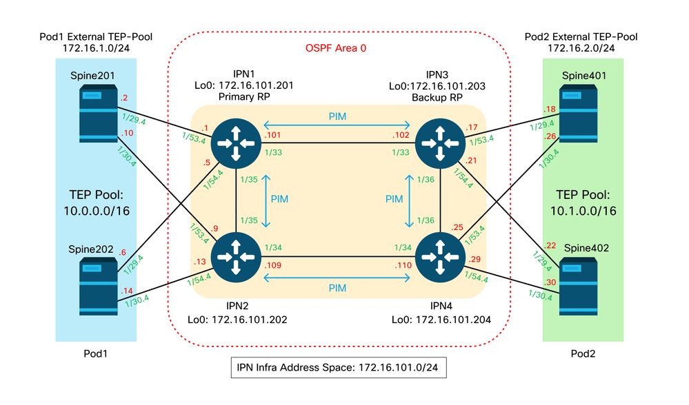
Spine to IPN dot1q VLAN-4 sub-interfaces connectivity
Spine to IPN point-to-point connectivity is achieved with sub-interfaces on VLAN-4. The first validation for this connectivity is to test IP reachability between the spines and the IPN devices.
To do so, determine the correct interface and verify it is showing as up.
S1P1-Spine201# show ip int brief vrf overlay-1 | grep 172.16.101.2
eth1/29.29           172.16.101.2/30      protocol-up/link-up/admin-up

S1P1-Spine201# show ip interface  eth1/29.29
IP Interface Status for VRF "overlay-1"
eth1/29.29, Interface status: protocol-up/link-up/admin-up, iod: 67, mode: external
  IP address: 172.16.101.2, IP subnet: 172.16.101.0/30
  IP broadcast address: 255.255.255.255
  IP primary address route-preference: 0, tag: 0

S1P1-Spine201# show system internal ethpm  info interface Eth1/29.29
Ethernet1/29.29 - if_index: 0x1A01C01D
Router MAC address: 00:22:bd:f8:19:ff
Admin Config Information:
  state(up), mtu(9150), delay(1), vlan(4), cfg-status(valid)
  medium(broadcast)
Operational (Runtime) Information:
  state(up), mtu(9150), Local IOD(0x43), Global IOD(0x43), vrf(enabled)
  reason(None)
  bd_id(29)
Information from SDB Query (IM call)
  admin state(up), runtime state(up), mtu(9150),
  delay(1), bandwidth(40000000), vlan(4), layer(L3),
  medium(broadcast)
  sub-interface(0x1a01c01d) from parent port(0x1a01c000)/Vlan(4)
  Operational Bits:

User config flags:  0x1
  admin_router_mac(1)

Sub-interface FSM state(3)
No errors on sub-interface
Information from GLDB Query:
Router MAC address: 00:22:bd:f8:19:ff
After verifying the Interface is up, now test point-to-point IP connectivity:
S1P1-Spine201# iping -V overlay-1 172.16.101.1
PING 172.16.101.1 (172.16.101.1) from 172.16.101.2: 56 data bytes
64 bytes from 172.16.101.1: icmp_seq=0 ttl=255 time=0.839 ms
64 bytes from 172.16.101.1: icmp_seq=1 ttl=255 time=0.719 ms
^C
--- 172.16.101.1 ping statistics ---
2 packets transmitted, 2 packets received, 0.00% packet loss
round-trip min/avg/max = 0.719/0.779/0.839 ms
If there is any connectivity issue, verify cabling and configuration on the remote IPN (IPN1).
IPN1# show ip interface brief | grep 172.16.101.1
Eth1/33              172.16.101.101  protocol-up/link-up/admin-up
Eth1/35              172.16.101.105  protocol-up/link-up/admin-up
Eth1/53.4            172.16.101.1    protocol-up/link-up/admin-up

IPN1# show run int Eth1/53.4
interface Ethernet1/53.4
description to spine 1pod1
mtu 9150
encapsulation dot1q 4
ip address 172.16.101.1/30
ip ospf cost 100
ip ospf network point-to-point
ip router ospf 1 area 0.0.0.0
ip pim sparse-mode
ip dhcp relay address 10.0.0.3
no shutdown
OSPF configuration
OSPF is used as the routing protocol to connect Pod1 and Pod2 together within ACI VRF 'overlay-1'. The following can be referenced as a generic flow to validate if OSPF is coming up between spine and IPN device.
S1P1-Spine201# show ip ospf neighbors vrf overlay-1
OSPF Process ID default VRF overlay-1
Total number of neighbors: 2
Neighbor ID     Pri State            Up Time  Address         Interface
172.16.101.201    1 FULL/ -          08:39:35 172.16.101.1    Eth1/29.29
172.16.101.202    1 FULL/ -          08:39:34 172.16.101.9    Eth1/30.30

S1P1-Spine201# show ip ospf  interface  vrf overlay-1
Ethernet1/29.29 is up, line protocol is up
   IP address 172.16.101.2/30, Process ID default VRF overlay-1, area backbone
   Enabled by interface configuration
   State P2P, Network type P2P, cost 1
   Index 67, Transmit delay 1 sec
   1 Neighbors, flooding to 1, adjacent with 1
   Timer intervals: Hello 10, Dead 40, Wait 40, Retransmit 5
     Hello timer due in 00:00:10
   No authentication
   Number of opaque link LSAs: 0, checksum sum 0
loopback0 is up, line protocol is up
   IP address 10.0.200.66/32, Process ID default VRF overlay-1, area backbone
   Enabled by interface configuration
   State LOOPBACK, Network type LOOPBACK, cost 1
 loopback14 is up, line protocol is up
   IP address 172.16.1.4/32, Process ID default VRF overlay-1, area backbone
   Enabled by interface configuration
   State LOOPBACK, Network type LOOPBACK, cost 1
 Ethernet1/30.30 is up, line protocol is up
   IP address 172.16.101.10/30, Process ID default VRF overlay-1, area backbone
   Enabled by interface configuration
   State P2P, Network type P2P, cost 1
   Index 68, Transmit delay 1 sec
   1 Neighbors, flooding to 1, adjacent with 1
   Timer intervals: Hello 10, Dead 40, Wait 40, Retransmit 5
     Hello timer due in 00:00:09
   No authentication
   Number of opaque link LSAs: 0, checksum sum 0

IPN1# show ip ospf  neighbors
OSPF Process ID 1 VRF default
Total number of neighbors: 5
Neighbor ID     Pri State            Up Time  Address         Interface
172.16.101.203    1 FULL/ -          4d12h    172.16.101.102  Eth1/33
172.16.101.202    1 FULL/ -          4d12h    172.16.101.106  Eth1/35
172.16.110.201    1 FULL/ -          4d12h    172.16.110.2    Eth1/48
172.16.1.4        1 FULL/ -          08:43:39 172.16.101.2    Eth1/53.4
172.16.1.6        1 FULL/ -          08:43:38 172.16.101.6    Eth1/54.4
When OSPF is up between all spines and IPN devices, all the Pod TEP pools can be seen within the IPN routing tables.
IPN1# show ip ospf database 10.0.0.0 detail
       OSPF Router with ID (172.16.101.201) (Process ID 1 VRF default)
                Type-5 AS External Link States
LS age: 183
Options: 0x2 (No TOS-capability, No DC)
LS Type: Type-5 AS-External
Link State ID: 10.0.0.0 (Network address)
Advertising Router: 172.16.1.4
LS Seq Number: 0x80000026
Checksum: 0x2da0
Length: 36
Network Mask: /16
      Metric Type: 2 (Larger than any link state path)
      TOS: 0
      Metric: 20
      Forward Address: 0.0.0.0
      External Route Tag: 0
LS age: 183
Options: 0x2 (No TOS-capability, No DC)
LS Type: Type-5 AS-External
Link State ID: 10.0.0.0 (Network address)
Advertising Router: 172.16.1.6
LS Seq Number: 0x80000026
Checksum: 0x21aa
Length: 36
Network Mask: /16
      Metric Type: 2 (Larger than any link state path)
      TOS: 0
      Metric: 20
      Forward Address: 0.0.0.0
      External Route Tag: 0

IPN1# show ip ospf database 10.1.0.0 detail
     OSPF Router with ID (172.16.101.201) (Process ID 1 VRF default)
                Type-5 AS External Link States
LS age: 1779
Options: 0x2 (No TOS-capability, No DC)
LS Type: Type-5 AS-External
Link State ID: 10.1.0.0 (Network address)
Advertising Router: 172.16.2.4
LS Seq Number: 0x80000022
Checksum: 0x22ad
Length: 36
Network Mask: /16
      Metric Type: 2 (Larger than any link state path)
      TOS: 0
      Metric: 20
      Forward Address: 0.0.0.0
      External Route Tag: 0
LS age: 1780
Options: 0x2 (No TOS-capability, No DC)
LS Type: Type-5 AS-External
Link State ID: 10.1.0.0 (Network address)
Advertising Router: 172.16.2.6
LS Seq Number: 0x80000022
Checksum: 0x16b7
Length: 36
Network Mask: /16
      Metric Type: 2 (Larger than any link state path)
      TOS: 0
      Metric: 20
      Forward Address: 0.0.0.0
      External Route Tag: 0

IPN1# show ip route 10.0.0.0
IP Route Table for VRF "default"
'*' denotes best ucast next-hop
'**' denotes best mcast next-hop
'[x/y]' denotes [preference/metric]
'%<string>' in via output denotes VRF <string>

10.0.0.0/16, ubest/mbest: 2/0
*via 172.16.101.2, Eth1/53.4, [110/20], 08:39:17, ospf-1, type-2
*via 172.16.101.6, Eth1/54.4, [110/20], 08:39:17, ospf-1, type-2

IPN1# show ip route 10.1.0.0
IP Route Table for VRF "default"
'*' denotes best ucast next-hop
'**' denotes best mcast next-hop
'[x/y]' denotes [preference/metric]
'%<string>' in via output denotes VRF <string>

10.1.0.0/16, ubest/mbest: 1/0
*via 172.16.101.102, Eth1/33, [110/20], 08:35:25, ospf-1, type-2
Notice on IPN1 for the remote Pod (Pod2), only the most optimal route is shown in the 'show ip route' command.
DHCP relay configuration
Switch nodes receive their infra TEP address utilizing DHCP towards the APICs. All APICs will typically receive the discover, but it is the first APIC to receive the discover and present an offer which will allocate the TEP address. To account for this in a Multi-Pod scenario, configure DHCP relay on the IPN to receive these discovers and unicast them towards the APICs. Generally, configure all IPN spine-facing interfaces with IP helpers pointing to all APICs. This will futureproof the IPN config if APIC is moved due to recabling, a standby APIC fails over, or any other scenarios that involve an APIC moving to a new Pod.
In this scenario, that means configuring IPN1 Eth1/53.4 and Eth1/54.4 with IP helpers pointing to all APICs:
interface Ethernet1/53.4
 description to  spine 1pod1
 mtu 9150
 encapsulation dot1q 4
 ip address 172.16.101.1/30
 ip ospf cost 100
 ip ospf network point-to-point
 ip router ospf 1 area 0.0.0.0
 ip pim sparse-mode
 ip dhcp relay address 10.0.0.1
 ip dhcp relay address 10.0.0.2
 ip dhcp relay address 10.0.0.3
 no shutdown

interface Ethernet1/54.4
 description to  spine 2pod1
 mtu 9150
 encapsulation dot1q 4
 ip address 172.16.101.5/30
 ip ospf cost 100
 ip ospf network point-to-point
 ip router ospf 1 area 0.0.0.0
 ip pim sparse-mode
 ip dhcp relay address 10.0.0.1
 ip dhcp relay address 10.0.0.2
 ip dhcp relay address 10.0.0.3
 no shutdown
From IPN3:
interface Ethernet1/53.4
 description to  spine 1pod2
 mtu 9150
 encapsulation dot1q 4
 ip address 172.16.101.17/30
 ip ospf cost 100
 ip ospf network point-to-point
 ip router ospf 1 area 0.0.0.0
 ip pim sparse-mode
 ip dhcp relay address 10.0.0.1
 ip dhcp relay address 10.0.0.2
 ip dhcp relay address 10.0.0.3
 no shutdown

interface Ethernet1/54.4
 description to  spine 2pod2
 mtu 9150
 encapsulation dot1q 4
 ip address 172.16.101.21/30
 ip ospf cost 100
 ip ospf network point-to-point
 ip router ospf 1 area 0.0.0.0
 ip pim sparse-mode
 ip dhcp relay address 10.0.0.1
 ip dhcp relay address 10.0.0.2
 ip dhcp relay address 10.0.0.3
 no shutdown
MTU
If OSPF is not coming up (EXCHANGE or EXSTART) between spine and IPN device, make sure to validate that MTU matches between devices.
RP configuration
With PIM BiDir, the Rendezvous Point (RP) is not part of the datapath. For functional multicast, each IPN device need only have a route to the RP address. Redundancy can be achieved using a Phantom RP configuration. In this case, Anycast RP is not a valid redundancy method due to not having a source to exchange via Multicast Source Discovery Protocol (MSDP).
In a Phantom RP design, the RP is a non-existent address in a reachable subnet. In the below config, assume the multicast range configured in the APIC initial setup is the default 225.0.0.0/15. If it was changed in APIC initial setup, IPN configurations must be aligned.
The loopback1 below is the phantom-rp loopback. It must be injected in OSPF; however, it can't be used as OPSF router-id. A separate loopback (loopback0) must be used for that.
IPN1 config:
interface loopback1
 description IPN1-RP-Loopback
 ip address 172.16.101.221/30
 ip ospf network point-to-point
 ip router ospf 1 area 0.0.0.0
 ip pim sparse-mode
ip pim rp-address 172.16.101.222 group-list 225.0.0.0/15 bidir
ip pim rp-address 172.16.101.222 group-list 239.255.255.240/32 bidir
IPN2 config:
ip pim rp-address 172.16.101.222 group-list 225.0.0.0/15 bidir
ip pim rp-address 172.16.101.222 group-list 239.255.255.240/32 bidir
IPN3 config:
interface loopback1
 description IPN3-RP-Loopback
 ip address 172.16.101.221/29
 ip ospf network point-to-point
 ip router ospf 1 area 0.0.0.0
 ip pim sparse-mode
ip pim rp-address 172.16.101.222 group-list 225.0.0.0/15 bidir
ip pim rp-address 172.16.101.222 group-list 239.255.255.240/32 bidir
IPN4 config:
ip pim rp-address 172.16.101.222 group-list 225.0.0.0/15 bidir
ip pim rp-address 172.16.101.222 group-list 239.255.255.240/32 bidir
The subnet mask on the loopback cannot be a /32. To use IPN1 as the primary device in the Phantom RP design, use a /30 subnet mask to take advantage of the most specific route being preferred in the OSPF topology. IPN3 will be the secondary device in the Phantom RP design, so use a /29 subnet mask to make it a less specific route. The /29 will only get used if something happens to stop the /30 from existing and subsequently existing within the OSPF topology.
Troubleshooting the 1st Remote Pod spine joining the fabric
The following steps outlines the process that the 1st Remote Pod Spine takes to join the fabric:
- The spine will do DHCP on its sub-interface facing the IPN. The DHCP Relay config will carry this discover to the APICs. The APICs will respond if the spine was added in the Fabric Membership. The IP address that gets offered is the IP address configured on the Multi-Pod L3Out.
- The spine will install a route towards the DHCP server that offered the IP address as a static route towards the other end of the point-to-point interface.
- The spine will download a bootstrap file from the APIC through the static route.
- The spine will get configured based on the bootstrap file to bring up VTEP, OSPF and BGP to join the fabric.
From the APIC, validate if the L3Out IP is properly configured to be offered: (our Spine 401 has serial FDO22472FCV)
bdsol-aci37-apic1# moquery -c dhcpExtIf

# dhcp.ExtIf
ifId         : eth1/30
childAction  :
dn           : client-[FDO22472FCV]/if-[eth1/30]
ip           : 172.16.101.26/30
lcOwn        : local
modTs        : 2019-10-01T09:51:29.966+00:00
name         :
nameAlias    :
relayIp      : 0.0.0.0
rn           : if-[eth1/30]
status       :
subIfId      : unspecified

# dhcp.ExtIf
ifId         : eth1/29
childAction  :
dn           : client-[FDO22472FCV]/if-[eth1/29]
ip           : 172.16.101.18/30
lcOwn        : local
modTs        : 2019-10-01T09:51:29.966+00:00
name         :
nameAlias    :
relayIp      : 0.0.0.0
rn           : if-[eth1/29]
status       :
subIfId      : unspecified
Validate if the IPN-facing interface received the expected IP address matching L3Out configuration done in infra Tenant.
S1P2-Spine401# show ip interface brief | grep eth1/29
eth1/29              unassigned           protocol-up/link-up/admin-up
eth1/29.29           172.16.101.18/30     protocol-up/link-up/admin-up
Now IP connectivity has been established from the spine to the APIC and connectivity through ping can be verified:
S1P2-Spine401# iping -V overlay-1 10.0.0.1
PING 10.0.0.1 (10.0.0.1) from 172.16.101.18: 56 data bytes
64 bytes from 10.0.0.1: icmp_seq=0 ttl=60 time=0.345 ms
64 bytes from 10.0.0.1: icmp_seq=1 ttl=60 time=0.294 ms
^C
--- 10.0.0.1 ping statistics ---
2 packets transmitted, 2 packets received, 0.00% packet loss
round-trip min/avg/max = 0.294/0.319/0.345 ms
The spine will now bring up the OSPF to the IPN and setup a loopback for the router id:
S1P2-Spine401# show ip ospf neighbors vrf overlay-1
OSPF Process ID default VRF overlay-1
Total number of neighbors: 2
Neighbor ID     Pri State            Up Time  Address         Interface
172.16.101.204    1 FULL/ -          00:04:16 172.16.101.25   Eth1/30.30
172.16.101.203    1 FULL/ -          00:04:16 172.16.101.17   Eth1/29.29

S1P2-Spine401# show ip ospf  interface  vrf overlay-1
loopback8 is up, line protocol is up
   IP address 172.16.2.4/32, Process ID default VRF overlay-1, area backbone
   Enabled by interface configuration
   State LOOPBACK, Network type LOOPBACK, cost 1
 Ethernet1/30.30 is up, line protocol is up
   IP address 172.16.101.26/30, Process ID default VRF overlay-1, area backbone
   Enabled by interface configuration
   State P2P, Network type P2P, cost 1
   Index 68, Transmit delay 1 sec
   1 Neighbors, flooding to 1, adjacent with 1
   Timer intervals: Hello 10, Dead 40, Wait 40, Retransmit 5
     Hello timer due in 00:00:07
   No authentication
   Number of opaque link LSAs: 0, checksum sum 0
Ethernet1/29.29 is up, line protocol is up
   IP address 172.16.101.18/30, Process ID default VRF overlay-1, area backbone
   Enabled by interface configuration
   State P2P, Network type P2P, cost 1
   Index 67, Transmit delay 1 sec
   1 Neighbors, flooding to 1, adjacent with 1
   Timer intervals: Hello 10, Dead 40, Wait 40, Retransmit 5
     Hello timer due in 00:00:04
   No authentication
   Number of opaque link LSAs: 0, checksum sum 0
The spine will now receive its PTEP trough DHCP:
S1P2-Spine401# show ip interface vrf overlay-1 | egrep -A 1 status
lo0, Interface status: protocol-up/link-up/admin-up, iod: 4, mode: ptep
IP address: 10.1.88.67, IP subnet: 10.1.88.67/32
The spine will move from Discovering to Active and is fully discovered:
bdsol-aci37-apic1# acidiag fnvread
     ID   Pod ID                 Name    Serial Number         IP Address    Role        State   LastUpdMsgId
--------------------------------------------------------------------------------------------------------------
    101        1         S1P1-Leaf101      FDO224702JA     10.0.160.64/32    leaf         active   0
    102        1         S1P1-Leaf102      FDO223007G7     10.0.160.67/32    leaf         active   0
    201        1        S1P1-Spine201      FDO22491705     10.0.160.65/32   spine         active   0
    202        1        S1P1-Spine202      FDO224926Q9     10.0.160.66/32   spine         active   0
    401        2        S1P2-Spine401      FDO22472FCV      10.1.88.67/32   spine         active   0
Please do know that we can only discover a remote spine when it has at least 1 leaf switch connected to it.
Verify remaining leaf and spine switches
The rest of the Pod is now discovered as per the normal Pod bring up procedure, as discussed in the section "Initial fabric setup".
Check remote Pod APIC
To discover the 3rd APIC, the following process is followed:
- The leaf301 creates a static route to the directly connected APIC (APIC3) based on LLDP (same as single Pod case)The remote APIC will receive an IP address out of the POD1 IP Pool. We will create this route as a /32.
- Leaf301 advertises this route using IS-IS to Spine401 and Spine402 (same as single Pod case)
- Spine401 and Spine402 redistribute this route into OSPF towards IPN
- Spine201 and Spine202 redistribute this route from OSPF to IS-IS in Pod1
- Now connectivity is established between APIC3 and APIC1 and APIC2
- APIC3 can now join the cluster
In order to confirm, use the following checks:
The Leaf301 creates a static route to the directly connected APIC (APIC3) based on LLDP (same as Single Pod case)
S1P2-Leaf301# show ip route 10.0.0.3 vrf overlay-1
IP Route Table for VRF "overlay-1"
'*' denotes best ucast next-hop
'**' denotes best mcast next-hop
'[x/y]' denotes [preference/metric]
'%<string>' in via output denotes VRF <string>

10.0.0.3/32, ubest/mbest: 2/0
   *via 10.1.88.64, eth1/50.14, [115/12], 00:07:21, isis-isis_infra, isis-l1-ext
   *via 10.1.88.67, eth1/49.13, [115/12], 00:07:15, isis-isis_infra, isis-l1-ext
    via 10.0.0.3, vlan9, [225/0], 07:31:04, static
Leaf301 advertises this route using IS-IS to Spine401 and Spine402 (same as single Pod case)
Spine401 and Spine402 leak this route into OSPF towards IPN
S1P2-Spine401# show ip route 10.0.0.3 vrf overlay-1
IP Route Table for VRF "overlay-1"
'*' denotes best ucast next-hop
'**' denotes best mcast next-hop
'[x/y]' denotes [preference/metric]
'%<string>' in via output denotes VRF <string>

10.0.0.3/32, ubest/mbest: 1/0
    *via 10.1.88.65, eth1/2.35, [115/11], 00:17:38, isis-isis_infra, isis-l1-ext  S1P2-Spine401#

IPN3# show ip route 10.0.0.3
IP Route Table for VRF "default"
'*' denotes best ucast next-hop
'**' denotes best mcast next-hop
'[x/y]' denotes [preference/metric]
'%<string>' in via output denotes VRF <string>

10.0.0.3/32, ubest/mbest: 2/0
    *via 172.16.101.18, Eth1/53.4, [110/20], 00:08:05, ospf-1, type-2
    *via 172.16.101.22, Eth1/54.4, [110/20], 00:08:05, ospf-1, type-2

S1P1-Spine201# show ip route vrf overlay-1 10.0.0.3
IP Route Table for VRF "overlay-1"
'*' denotes best ucast next-hop
'**' denotes best mcast next-hop
'[x/y]' denotes [preference/metric]
'%<string>' in via output denotes VRF <string>

10.0.0.3/32, ubest/mbest: 2/0
    *via 172.16.101.1, eth1/29.29, [110/20], 00:08:59, ospf-default, type-2
    *via 172.16.101.9, eth1/30.30, [110/20], 00:08:59, ospf-default, type-2
    via 10.0.160.64, eth1/1.36, [115/12], 00:18:19, isis-isis_infra, isis-l1-ext
    via 10.0.160.67, eth1/2.35, [115/12], 00:18:19, isis-isis_infra, isis-l1-ext
Now connectivity is established between APIC3 and APIC1 and APIC2
APIC3 can now join the cluster
apic1# show controller
Fabric Name          : POD37
Operational Size     : 3
Cluster Size         : 3
Time Difference      : 133
Fabric Security Mode : PERMISSIVE
 ID    Pod   Address          In-Band IPv4     In-Band IPv6               OOB IPv4         OOB IPv6                        Version             Flags  Serial Number     Health
----  ----  ---------------  ---------------  -------------------------  ---------------  ------------------------------  ------------------  -----  ----------------  ------------------
1*    1     10.0.0.1         0.0.0.0          fc00::1                    10.48.176.57     fe80::d6c9:3cff:fe51:cb82       4.2(1i)             crva-  WZP22450H82       fully-fit
2     1     10.0.0.2         0.0.0.0          fc00::1                    10.48.176.58     fe80::d6c9:3cff:fe51:ae22       4.2(1i)             crva-  WZP22441AZ2       fully-fit
3     2     10.0.0.3         0.0.0.0          fc00::1                    10.48.176.59     fe80::d6c9:3cff:fe51:a30a       4.2(1i)             crva-  WZP22441B0T       fully-fit
Flags - c:Commissioned | r:Registered | v:Valid Certificate | a:Approved | f/s:Failover fail/success
(*)Current (~)Standby (+)AS
Ping from APIC1 to a remote device in Pod2 to validate connectivity via the following ping: (make sure to source from the local interface, in APIC1 case 10.0.0.1)
apic1# ping 10.0.0.3 -I 10.0.0.1
PING 10.0.0.3 (10.0.0.3) from 10.0.0.1 : 56(84) bytes of data.
64 bytes from 10.0.0.3: icmp_seq=1 ttl=58 time=0.132 ms
64 bytes from 10.0.0.3: icmp_seq=2 ttl=58 time=0.236 ms
64 bytes from 10.0.0.3: icmp_seq=3 ttl=58 time=0.183 ms
^C
--- 10.0.0.3 ping statistics ---
3 packets transmitted, 3 received, 0% packet loss, time 2048ms
rtt min/avg/max/mdev = 0.132/0.183/0.236/0.045 ms
Troubleshooting Scenarios
Spine cannot ping the IPN
This is most likely caused by:
- A misconfiguration in the ACI Access Policies.
- A misconfiguration in the IPN configuration.
Please refer to the "Troubleshooting workflow" in this chapter and review:
- Verify ACI Policies.
- IPN Validation.
Remote spine is not joining fabric
This is most likely caused by:
- DHCP relay issue on IPN network.
- Spine-to-APIC IP reachability over the IPN network.
Please refer to the "Troubleshooting workflow" in this chapter and review:
- Verify ACI Policies.
- IPN Validation.
- Troubleshoot 1st fabric join.
Make sure to validate that there is at least 1 leaf connected to the remote spine and that the spine has an LLDP adjacency with this leaf.
APIC in Pod2 is not joining fabric
This is typically caused by a mistake in the APIC initial setup dialog assuming the remote Pod leaf and spine switches were able to correctly join the fabric. In a correct setup, expect the following 'avread' output (working APIC3 join scenario):
apic1# avread
Cluster:
-------------------------------------------------------------------------
fabricDomainName        POD37
discoveryMode           PERMISSIVE
clusterSize             3
version                 4.2(1i)
drrMode                 OFF
operSize                3
APICs:
-------------------------------------------------------------------------
                   APIC 1                  APIC 2                  APIC 3
version           4.2(1i)                 4.2(1i)                 4.2(1i)
address           10.0.0.1                10.0.0.2                10.0.0.3
oobAddress        10.48.176.57/24         10.48.176.58/24         10.48.176.59/24
routableAddress   0.0.0.0                 0.0.0.0                 0.0.0.0
tepAddress        10.0.0.0/16             10.0.0.0/16             10.0.0.0/16
podId             1                       1                       2
chassisId         7e34872e-.-d3052cda     84debc98-.-e207df70     89b73e48-.-f6948b98
cntrlSbst_serial  (APPROVED,WZP22450H82)  (APPROVED,WZP22441AZ2)  (APPROVED,WZP22441B0T)
active            YES                     YES                     YES
flags             cra-                    cra-                    cra-
health            255                     255                     255
Notice that APIC3 (in the remote Pod) is configured with podId 2 and the tepAddress of Pod1.
Verify the original APIC3 setup settings by using the following command:
apic3# cat /data/data_admin/sam_exported.config
Setup for Active and Standby APIC
fabricDomain = POD37
fabricID = 1
systemName =bdsol-aci37-apic3
controllerID = 3
tepPool = 10.0.0.0/16
infraVlan = 3937
clusterSize = 3
standbyApic = NO
enableIPv4 = Y
enableIPv6 = N
firmwareVersion = 4.2(1i)
ifcIpAddr = 10.0.0.3
apicX = NO
podId = 2
oobIpAddr = 10.48.176.59/24
If a mistake occurs, login to APIC3 and execute 'acidiag touch setup' and 'acidiag reboot'.
POD-to-POD BUM traffic not working
This is most likely caused by:
- The lack of an RP in the IP network
- The RP not reachable by the ACI fabricGeneral Multicast misconfiguration on the IPN devices
Please refer to the "Troubleshooting workflow" in this chapter and review:
- IPN Validation
Also make sure one of the IPN RP devices is online.
After 1 IPN device failed, BUM traffic is being dropped
As described in the IPN Validation in the troubleshooting workflow, use a Phantom RP to guarantee when the primary RP goes down that a secondary RP is available. Make sure to review the "IPN Validation" section and verify the correct validation.
Inter-Pod endpoint connectivity is broken within the same EPG
This is most likely caused by a misconfiguration in the Multi-Pod setup, make sure to validate the troubleshooting workflow and verify the entire flow. If this looks OK, please refer to the "Multi-Pod forwarding" section in the chapter "Intra-Fabric forwarding" to further troubleshoot this issue.
Revision History
| Revision | Publish Date | Comments |
|---|---|---|
1.0 |
08-Aug-2022 |
Initial Release |
Contributed by Cisco Engineers
- ACI Escalation Engineers
- Technical Marketing
Contact Cisco
- Open a Support Case

- (Requires a Cisco Service Contract)
 Feedback