Troubleshoot ACI Management and Core Services - Pod Policies
Available Languages
Download Options
Bias-Free Language
The documentation set for this product strives to use bias-free language. For the purposes of this documentation set, bias-free is defined as language that does not imply discrimination based on age, disability, gender, racial identity, ethnic identity, sexual orientation, socioeconomic status, and intersectionality. Exceptions may be present in the documentation due to language that is hardcoded in the user interfaces of the product software, language used based on RFP documentation, or language that is used by a referenced third-party product. Learn more about how Cisco is using Inclusive Language.
Contents
Introduction
This document describes steps to understand and troubleshoot ACI Pod Policies.
Background Information
The material from this document was extracted from the Troubleshooting Cisco Application Centric Infrastructure, Second Edition book, specifically the Management and Core Services - POD Policies - BGP RR/ Date&Time / SNMP chapter.
Pod Policies Overview
Management services such as BGP RR, Date & Time and SNMP are applied on the system using a Pod Policy Group. A Pod Policy Group governs a group of Pod Policies related to essential functions of an ACI Fabric. These Pod Policies relate to the following components, many of which are provisioned in an ACI fabric by default.
Pod Policies
|
Pod Policy |
Requires Manual Config |
|
Date & Time |
Yes |
|
BGP Route Reflector |
Yes |
|
SNMP (server network management protocol) |
Yes |
|
ISIS |
No |
|
COOP |
No |
|
Management Access |
No |
|
MAC Sec |
Yes |
Even in a single ACI fabric, the Pod Policy Group and Pod Profile need to be configured. This is not specific to a Multi-Pod or even a Multi-Site deployment. The requirement applies to all ACI deployment types.
This chapter focuses on these essential Pod Policies and how to verify they're applied correctly.
Date & Time policy
Time synchronization plays a critical role in the ACI fabric. From validating certificates, to keeping log timestamps in APICs and switches consistent, it is best practice to sync the nodes in the ACI fabric to one or more reliable time sources using NTP.
In order to properly have the nodes synchronized to an NTP server provider, there's a dependency to assign nodes with management addresses. This can be done under the management tenant using either Static Node Management Addresses or Management Node Connectivity Groups.
Troubleshooting Workflow
1. Verify if Node Management Addresses are assigned to all nodes
Management tenant - Node Management Addresses

2. Verify if an NTP server has been configured as an NTP provider
If there are multiple NTP providers, flag at least one of them as the preferred time source using the 'Preferred' checkbox as per the figure below.
NTP Provider/Server under Date and Time Pod Policy

3. Verify the Date and Time format under System Settings
The figure below shows an example whereby the Date and Time format has been set to UTC.
Date and Time setting under System Settings

4. Verify the operational Sync Status of the NTP provider for all nodes
As shown in the figure below, the Sync Status column should show 'Synced to Remote NTP Server'. Be aware that it can take several minutes for the Sync Status to converge properly to the .Synced to Remote NTP Server. status.
NTP Provider/Server Sync Status

Alternatively, CLI methods can be used on the APICs and the switches to verify correct time sync against the NTP Server.
APIC - NX-OS CLI
The 'refId' column below shows the NTP Servers next time source depending on the stratum.
apic1# show ntpq
nodeid     remote                          refid                       st        t   when      poll      reach     auth  delay     offset    jitter
------  -  ------------------------------  --------------------------  --------  --  --------  --------  --------  ----  --------  --------  --------
1       *  10.48.37.151                    192.168.1.115               2         u   25        64        377       none  0.214     -0.118    0.025
2       *  10.48.37.151                    192.168.1.115               2         u   62        64        377       none  0.207     -0.085    0.043
3       *  10.48.37.151                    192.168.1.115               2         u   43        64        377       none  0.109     -0.072    0.030


apic1# show clock
Time : 17:38:05.814 UTC Wed Oct 02 2019
APIC - Bash
apic1# bash
admin@apic1:~> date
Wed Oct  2 17:38:45 UTC 2019
Switch
Use the 'show ntp peers' command to make sure the NTP provider configuration has been properly pushed to the switch.
leaf1# show ntp peers
-----------------------------------------------------------------------------
    Peer IP Address                         Serv/Peer Prefer KeyId   Vrf
-----------------------------------------------------------------------------
    10.48.37.151                            Server    yes    None    management

leaf1# show ntp peer-status
Total peers : 1
* - selected for sync, + - peer mode(active),
- - peer mode(passive), = - polled in client mode
    remote                               local           st poll reach delay vrf
--------------------------------------------------------------------------------
*10.48.37.151                            0.0.0.0         2  64   377   0.000  management
The '*' character is essential here as it governs whether the NTP server is actually being used for sync.
Verify the number of packets sent/received in the following command to make sure ACI nodes have reachability to the NTP server.
leaf1# show ntp statistics peer ipaddr 10.48.37.151
...
packets sent:         256
packets received:     256
...
BGP Route Reflector policy
An ACI fabric uses multi-protocol BGP (MP-BGP) and, more specifically, iBGP VPNv4 between leaf and spine nodes to exchange tenant routes received from external routers (connected on L3Outs). To avoid a full mesh iBGP peer topology, the spine nodes reflect VPNv4 prefixes received from a leaf to other leaf nodes in the fabric.
Without the BGP Route Reflector (BGP RR) Policy, no BGP instance will be created on the switches and BGP VPNv4 sessions won't be established. In a Multi-Pod deployment, each Pod requires at least one spine configured as a BGP RR and essentially more than one for redundancy.
As a result, the BGP RR Policy is an essential piece of configuration in every ACI Fabric. The BGP RR Policy also contains the ASN the ACI Fabric uses for the BGP process on each switch.
Troubleshooting Workflow
1. Verify if the BGP RR Policy has an ASN and at least one spine configured
The example below refers to a single Pod deployment.
BGP Route Reflector Policy under System Settings

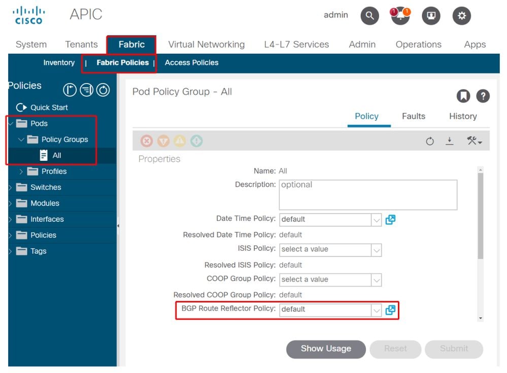
2. Verify if the BGP RR Policy is applied under the Pod Policy Group
Apply a default BGP RR Policy under the Pod Policy Group. Even if the entry is blank, the default BGP RR Policy will be applied as part of the Pod Policy Group.
BGP Route Reflector Policy applied under Pod Policy Group

3. Verify if the Pod Policy Group is applied under the Pod Profile
Pod Policy Group applied under the Pod Profile

4. Log into a spine and verify if the BGP Process is running with established VPN4 peer sessions
spine1# show bgp process vrf overlay-1

BGP Process Information
BGP Process ID                 : 26660
BGP Protocol Started, reason:  : configuration
BGP Protocol Tag               : 65001
BGP Protocol State             : Running
BGP Memory State               : OK
BGP asformat                   : asplain
Fabric SOO                     : SOO:65001:33554415
Multisite SOO                  : SOO:65001:16777199
Pod SOO                        : SOO:1:1
...
    Information for address family VPNv4 Unicast in VRF overlay-1
    Table Id                   : 4
    Table state                : UP
    Table refcount             : 9
    Peers      Active-peers    Routes     Paths      Networks   Aggregates
      7          6               0          0          0          0

    Redistribution
        None

    Wait for IGP convergence is not configured
    Additional Paths Selection route-map interleak_rtmap_golf_rtmap_path_advertise_all
    Is a Route-reflector

    Nexthop trigger-delay
        critical 500 ms
        non-critical 5000 ms

    Information for address family VPNv6 Unicast in VRF overlay-1
    Table Id                   : 80000004
    Table state                : UP
    Table refcount             : 9
    Peers      Active-peers    Routes     Paths      Networks   Aggregates
    7          6               0          0          0          0

    Redistribution
        None

    Wait for IGP convergence is not configured
    Additional Paths Selection route-map interleak_rtmap_golf_rtmap_path_advertise_all
    Is a Route-reflector

    Nexthop trigger-delay
        critical 500 ms
        non-critical 5000 ms
    ...
    Wait for IGP convergence is not configured
    Is a Route-reflector

    Nexthop trigger-delay
        critical 500 ms
        non-critical 5000 ms
As shown above, MP-BGP between leaf and spine nodes carries only VPNv4 and VPNv6 address families. The IPv4 address family is used in MP-BGP only on leaf nodes.
The BGP VPNv4 and VPNv6 sessions between spine and leaf nodes can also be easily observed using the following command.
spine1# show bgp vpnv4 unicast summary vrf overlay-1
BGP summary information for VRF overlay-1, address family VPNv4 Unicast
BGP router identifier 10.0.136.65, local AS number 65001
BGP table version is 15, VPNv4 Unicast config peers 7, capable peers 6
0 network entries and 0 paths using 0 bytes of memory
BGP attribute entries [0/0], BGP AS path entries [0/0]
BGP community entries [0/0], BGP clusterlist entries [0/0]

Neighbor        V      AS MsgRcvd MsgSent   TblVer  InQ OutQ Up/Down  State/PfxRcd
10.0.136.64     4   65001     162     156       15    0    0 02:26:00 0
10.0.136.67     4   65001     154     154       15    0    0 02:26:01 0
10.0.136.68     4   65001     152     154       15    0    0 02:26:00 0
10.0.136.69     4   65001     154     154       15    0    0 02:26:01 0
10.0.136.70     4   65001     154     154       15    0    0 02:26:00 0
10.0.136.71     4   65001     154     154       15    0    0 02:26:01 0


spine1# show bgp vpnv6 unicast summary vrf overlay-1
BGP summary information for VRF overlay-1, address family VPNv6 Unicast
BGP router identifier 10.0.136.65, local AS number 65001
BGP table version is 15, VPNv6 Unicast config peers 7, capable peers 6
0 network entries and 0 paths using 0 bytes of memory
BGP attribute entries [0/0], BGP AS path entries [0/0]
BGP community entries [0/0], BGP clusterlist entries [0/0]

Neighbor        V      AS MsgRcvd MsgSent   TblVer  InQ OutQ Up/Down  State/PfxRcd
10.0.136.64     4   65001     162     156       15    0    0 02:26:11 0
10.0.136.67     4   65001     155     155       15    0    0 02:26:12 0
10.0.136.68     4   65001     153     155       15    0    0 02:26:11 0
10.0.136.69     4   65001     155     155       15    0    0 02:26:12 0
10.0.136.70     4   65001     155     155       15    0    0 02:26:11 0
10.0.136.71     4   65001     155     155       15    0    0 02:26:12 0
Note the 'Up/Down' column from the above output. It should list a duration time which denotes the time the BGP session has been established. Also note in the example the 'PfxRcd' column shows 0 for each BGP VPNv4/VPNv6 peer as this ACI Fabric has no L3Outs configured yet and as such no external routes/prefixes are exchanges between leaf and spine nodes.
5. Log into a leaf and verify if the BGP Process is running with established VPN4 peer sessions
leaf1# show bgp process vrf overlay-1

BGP Process Information
BGP Process ID                 : 43242
BGP Protocol Started, reason:  : configuration
BGP Protocol Tag               : 65001
BGP Protocol State             : Running
...

leaf1#  show bgp vpnv4 unicast summary vrf overlay-1
BGP summary information for VRF overlay-1, address family VPNv4 Unicast
BGP router identifier 10.0.136.64, local AS number 65001
BGP table version is 7, VPNv4 Unicast config peers 2, capable peers 2
0 network entries and 0 paths using 0 bytes of memory
BGP attribute entries [0/0], BGP AS path entries [0/0]
BGP community entries [0/0], BGP clusterlist entries [0/0]

Neighbor        V      AS MsgRcvd MsgSent   TblVer  InQ OutQ Up/Down  State/PfxRcd
10.0.136.65     4   65001     165     171        7    0    0 02:35:52 0
10.0.136.66     4   65001     167     171        7    0    0 02:35:53 0
The above command outputs show an amount of BGP VPNv4 sessions equal to the number of spine nodes present in the ACI Fabric. This differs from the spine nodes because they establish sessions to each leaf and the other route reflector spine nodes.
SNMP
It is important to clarify from the start which specific subset of SNMP functions this section covers. SNMP functions in an ACI fabric either relate to the SNMP Walk function or the SNMP Trap function. The important distinction here is that SNMP Walk governs ingress SNMP traffic flows on UDP port 161 whereas SNMP Trap governs outgoing SNMP traffic flows with an SNMP Trap server listening on UDP port 162.
Ingress management traffic on ACI nodes require the Node Management EPGs (either in-band or out-of-band) to provide the necessary contracts to allow the traffic to flow. As such this also applies to ingress SNMP traffic flows.
This section will cover the ingress SNMP traffic flows (SNMP Walks) into ACI nodes (APICs and switches). It will not cover the egress SNMP traffic flows (SNMP Traps) as that would expand the scope of this section into Monitoring Policies and Monitoring Policy dependencies (i.e. Monitoring Policy scope, Monitoring Packages, etc.).
This section also won't cover which SNMP MIBs are supported by ACI. That information is available on the Cisco CCO website in the following link: https://www.cisco.com/c/dam/en/us/td/docs/switches/datacenter/aci/apic/sw/1-x/mib/list/mib-support.html
Troubleshooting Workflow
1. SNMP Pod Policy — Verify if a Client Group Policy is configured
Make sure at least a single SNMP Client is configured as part of the Client Group Policy as per screenshots below.
Pod Policies — SNMP Policy — Client Group Policies

Pod Policies — SNMP Policy — Client Group Policies

2. SNMP Pod Policy — Verify if at least one Community Policy is configured
Pod Policies — SNMP Policy — Community Policies

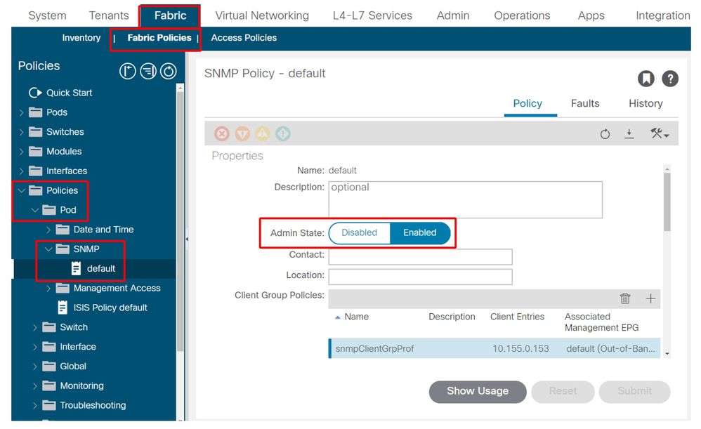
3. SNMP Pod Policy — Verify if the Admin State is set to 'Enabled'

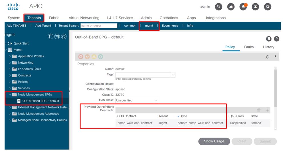
4. Management tenant — verify if the OOB EPG is providing an OOB Contract allowing UDP port 161
The OOB EPG governs connectivity into the APIC and switch OOB management ports. As such it affects all traffic flows ingressing into the OOB ports.
Make sure the contract which is provided here includes all necessary management services instead of just SNMP. For example: it also needs to include at least SSH (TCP port 22). Without this it is not possible to log into the switches using SSH. Please note this does not apply to APICs as they have a mechanism to allow SSH, HTTP, HTTPS to prevent users from being locked up completely.

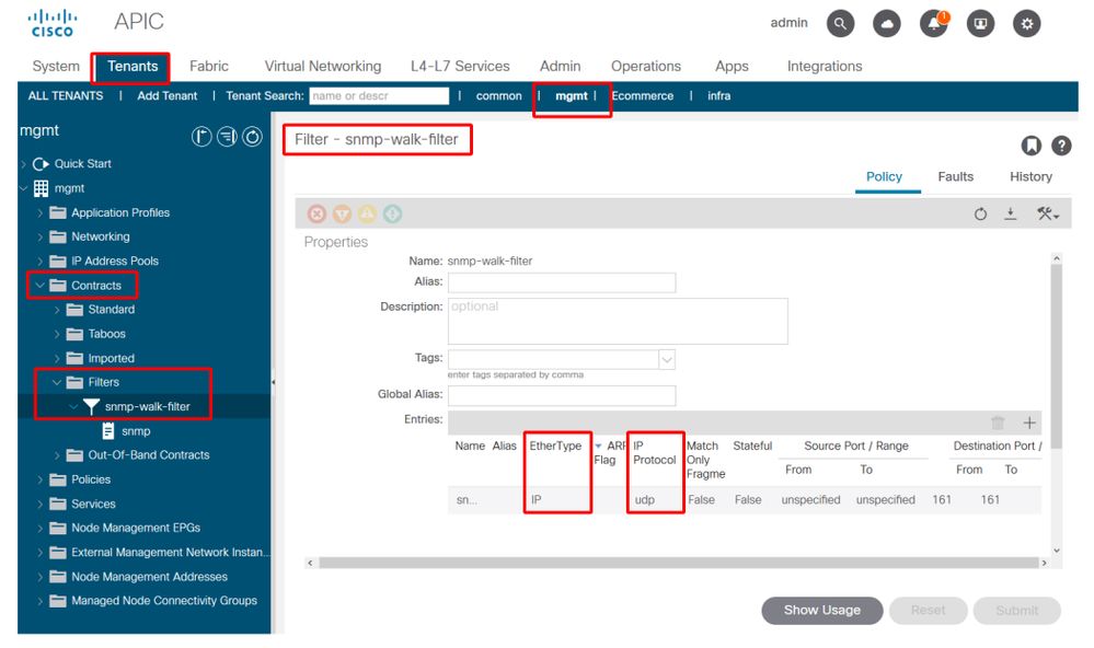
5. Management tenant — verify if the OOB Contract is present and has a filter allowing UDP port 161
Management tenant — OOB EPG — Provided OOB Contract

In the figure below, it is not mandatory to just allow UDP port 161. A contract that has a filter allowing UDP port 161 in any manner is correct. This can even be a contract subject with the default filter from the common tenant. In our example, for clarity purposes, a specific filter was configured just for UDP port 161.

6. Management tenant — verify if an External Management Network Instance Profile is present with a valid Subnet consuming the OOB Contract
The external management network instance profile (ExtMgmtNetInstP) represents external sources defined by the 'Subnets' in there that need to consume services reachable via the OOB EPG. So, the ExtMgmtNetInstP consumes the same OOB contract which is provided by the OOB EPG. This is the contract allowing UDP port 161. In addition, the ExtMgmtNetInstP also specifies the allowed subnet ranges that may consume the services provided by the OOB EPG.
Management tenant — ExtMgmtNetInstP with consumed OOB Contract and Subnet

As shown in the figure above, a CIDR-based subnet notation is required. The figure shows a specific /24 subnet. The requirement is that the subnet entries cover the SNMP Client Entries as configured in the SNMP Pod Policy (refer to Figure Pod Policies — SNMP Policy — Client Group Policies).
As mentioned earlier, please be careful to include all required external subnets to prevent other necessary management services from being locked out.
7. Log into a switch and perform a tcpdump to observe if SNMP Walk packets — UDP port 161 — are observed
If SNMP Walk packets are entering a switch through the OOB port, this means all necessary SNMP and OOB based policies/parameters have been properly configured. Hence, it's a proper verification method.
Tcpdump on the leaf nodes leverages their Linux shell and Linux netdevices. Hence, it's necessary to capture the packets on interface 'eth0' as per below example. In the example, an SNMP client is performing an SNMP Get request against OID .1.0.8802.1.1.2.1.1.1.0.
leaf1# ip addr show eth0
2: eth0: <BROADCAST,MULTICAST,UP,LOWER_UP> mtu 1500 qdisc mq state UP qlen 1000
    link/ether f4:cf:e2:28:fc:ac brd ff:ff:ff:ff:ff:ff
    inet 10.48.22.77/24 brd 10.48.22.255 scope global eth0
        valid_lft forever preferred_lft forever
    inet6 fe80::f6cf:e2ff:fe28:fcac/64 scope link
        valid_lft forever preferred_lft forever


leaf1# tcpdump -i eth0 udp port 161
tcpdump: verbose output suppressed, use -v or -vv for full protocol decode
listening on eth0, link-type EN10MB (Ethernet), capture size 65535 bytes
22:18:10.204011 IP 10.155.0.153.63392 > 10.48.22.77.snmp:  C=my-snmp-community GetNextRequest(28)  .iso.0.8802.1.1.2.1.1.1.0
22:18:10.204558 IP 10.48.22.77.snmp > 10.155.0.153.63392:  C=my-snmp-community GetResponse(29)  .iso.0.8802.1.1.2.1.1.2.0=4
Revision History
| Revision | Publish Date | Comments |
|---|---|---|
1.0 |
08-Aug-2022 |
Initial Release |
Contributed by Cisco Engineers
- ACI Escalation Engineers
- Technical Marketing
Contact Cisco
- Open a Support Case

- (Requires a Cisco Service Contract)
 Feedback