Troubleshoot ACI vPC
Available Languages
Download Options
Bias-Free Language
The documentation set for this product strives to use bias-free language. For the purposes of this documentation set, bias-free is defined as language that does not imply discrimination based on age, disability, gender, racial identity, ethnic identity, sexual orientation, socioeconomic status, and intersectionality. Exceptions may be present in the documentation due to language that is hardcoded in the user interfaces of the product software, language used based on RFP documentation, or language that is used by a referenced third-party product. Learn more about how Cisco is using Inclusive Language.
Contents
Introduction
This document describes the commands required to identify issues with Virtual Port-Channel (vPC) communication on ACI.
Prerequisites
Requirements
There are no specific requirements for this document.
Components Used
This document is not restricted to specific software and hardware versions.
The information in this document was created from the devices in a specific lab environment. All of the devices used in this document started with a cleared (default) configuration. If your network is live, ensure that you understand the potential impact of any command.
Background Information
The vPC between Application Centric Infrastructure (ACI) and the peer device must have been previously up and functional without configuration issues.
Configure
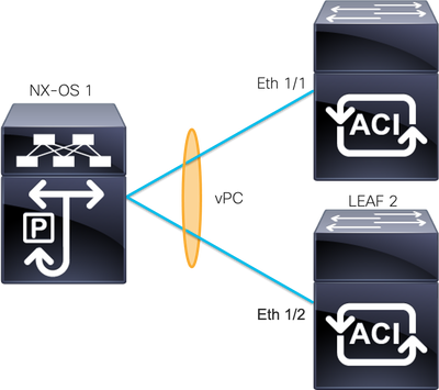
Topology Explanation
ACI LEAF 1: interface Ethernet 1/1, Port-Channel 5 and vPC 343.
ACI LEAF 2: interface Ethernet 1/2, Port-Channel 5 and vPC 343.
NX-OS 1: interfaces Ethernet 1/1 and Ethernet 1/2, Port-Channel 14 and vPC 45.
Connections:
LEAF 1 Eth1/1 <-> NX-OS 1 Eth1/1
LEAF 2 Eth1/2 <-> NX-OS 1 Eth1/2
Network Diagram

Verify
Use this section to confirm that your configuration works properly.
The Cisco CLI Analyzer (registered customers only) supports certain show commands. Use the Cisco CLI Analyzer in order to view an analysis of the show command output.
With the commandshow vpc brief vpc xyou can see the status of the vPC (Up/Down).
LEAF1#show vpc brief vpc 343
vPC status
----------------------------------------------------------------------
id   Port   Status Consistency Reason                 Active vlans
--   ----   ------ ----------- ------                 ------------
343  Po5    up     success     success                100
LEAF2#show vpc brief vpc 343
vPC status
----------------------------------------------------------------------
id   Port   Status Consistency Reason                 Active vlans
--   ----   ------ ----------- ------                 ------------
343  Po5    up     success     success                100
With the command show port-channel summary interface port-channel x you can see the status of the Port-Channel (Up/Down), the current flags, and the physical interface where it is configured.
LEAF1#show port-channel summary interface port-channel 5
Flags:  D - Down        P - Up in port-channel (members)
        I - Individual  H - Hot-standby (LACP only)
        s - Suspended   r - Module-removed
        S - Switched    R - Routed
        U - Up (port-channel)
        M - Not in use. Min-links not met
        F - Configuration failed
-------------------------------------------------------------------------------
Group Port-       Type     Protocol  Member Ports
      Channel
-------------------------------------------------------------------------------
5     Po5(SU)     Eth      LACP      Eth1/1(P)
LEAF2#show port-channel summary interface port-channel 5
Flags:  D - Down        P - Up in port-channel (members)
        I - Individual  H - Hot-standby (LACP only)
        s - Suspended   r - Module-removed
        S - Switched    R - Routed
        U - Up (port-channel)
        M - Not in use. Min-links not met
        F - Configuration failed
-------------------------------------------------------------------------------
Group Port-       Type     Protocol  Member Ports
      Channel
-------------------------------------------------------------------------------
5     Po5(SU)     Eth      LACP      Eth1/2(P)
Troubleshoot
This section provides the information you can use to troubleshoot your configuration.
Miscable Issues
On the APIC GUI, you must see this fault:
Fault F0518: A configuration is not consistent with peer node. Misconfigured due to vPC link in the 2 switches connected to different partners.

ACI LEAF 1: interface Ethernet 1/1, Port-Channel 5 and vPC 343.
ACI LEAF 2: interface Ethernet 1/2, Port-Channel 5 and vPC 343.
NXOS 1: interfaces Ethernet 1/1 and Ethernet 1/2, Port-Channel 14 and vPC 45.
Connections:
LEAF 1 Eth1/1 <-> NXOS 1 Eth1/1
LEAF 2 Eth1/2 <-> NXOS 1 Eth1/2
If you run into this issue the outputs look like the example:
LEAF1#show vpc brief vpc 343
vPC status
----------------------------------------------------------------------
id   Port   Status Consistency Reason                 Active vlans
--   ----   ------ ----------- ------                 ------------
343  Po5    up     failed      vpc port               100
                               channel
                               mis-config
                               due to vpc
                               links in the
                               2 switches
                               connected to
                               different
                               partners
LEAF2#show vpc brief vpc 343
vPC status
----------------------------------------------------------------------
id   Port   Status Consistency Reason                 Active vlans
--   ----   ------ ----------- ------                 ------------
343  Po5    up     failed      vpc port               100
                               channel
                               mis-config
                               due to vpc
                               links in the
                               2 switches
                               connected to
                               different
                               partners
LEAF1#show port-channel summary interface port-channel 5
Flags:  D - Down        P - Up in port-channel (members)
        I - Individual  H - Hot-standby (LACP only)
        s - Suspended   r - Module-removed
        S - Switched    R - Routed
        U - Up (port-channel)
        M - Not in use. Min-links not met
        F - Configuration failed
-------------------------------------------------------------------------------
Group Port-       Type     Protocol  Member Ports
      Channel
-------------------------------------------------------------------------------
5     Po5(SD)     Eth      LACP      Eth1/1(D)
LEAF2#show port-channel summary interface port-channel 5
Flags:  D - Down        P - Up in port-channel (members)
        I - Individual  H - Hot-standby (LACP only)
        s - Suspended   r - Module-removed
        S - Switched    R - Routed
        U - Up (port-channel)
        M - Not in use. Min-links not met
        F - Configuration failed
-------------------------------------------------------------------------------
Group Port-       Type     Protocol  Member Ports
      Channel
-------------------------------------------------------------------------------
5     Po5(SD)     Eth      LACP      Eth1/2(D)
LEAF1# show lacp interface ethernet 1/1 | grep Lag
Lag Id: [ [(7f9b, 0-11-1-aa-aa-aa, 8157, 8000, 10d), (8000, 0-22-2-bb-bb-bb, 65, 8000, 125)] ]
LEAF2# show lacp interface ethernet 1/2 | grep Lag
Lag Id: [ [(7f9b, 0-11-1-aa-aa-aa, 8157, 8000, 10d), (8000, 0-33-3-cc-cc-cc, 65, 8000, 125)] ]The connected device lag information (second vector on the output command) must be the same on both outputs. As well, vector one must be the same on both.
Next Step:
If you have this behavior, the physical connections must be reviewed to ensure that the connections have not been swapped on the ports.
Individual Port by Loop Detected
On the APIC GUI, you must see these faults:
Fault F2705: A vPC interface goes down while peer interface is up.

Fault F2533: A loop was detected by the MCP protocol on ACI.
This issue affects vPC topologies where STP protocol runs on the peer devices.

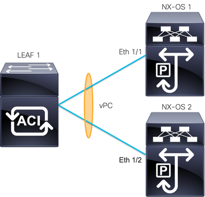
ACI LEAF 1: interface Ethernet 1/1 and Ethernet 1/2, Port-Channel 5 and vPC 343
NXOS 1: interfaces Ethernet 1/1, Port-Channel 14 and vPC 45
NXOS 2: interfaces Ethernet 1/2, Port-Channel 14 and vPC 45
Connections:
LEAF 1 Eth1/1 <-> NXOS 1 Eth1/1
LEAF 1 Eth1/2 <-> NXOS 2 Eth1/2
For this troubleshoot step, it is important to understand the concept of MisCabling Protocol (MCP).
MCP detects loops from external sources (misbehavior of servers, external network equipment that uses STP, and so on) and err-disable the interface on which ACI receives its own packet.
To learn more about MCP see: Using MCP for ACI.
If you have this issue, the outputs look like this:
LEAF2#show mcp internal info interface eth 1/2
------------------------------------------
Interface: Ethernet1/2
Native PI VLAN: 100
Native Encap VLAN: 1
BPDU Guard: disabled
BPDU Filter: disabled
Port State: down
Layer3 Port: false
Switching State: enabled
Mac Address: AA:AA:AA:AA:AA:01
Interface MCP enabled: true
------------------- STP STATS --------------------
MSTP Count: 0
RSTP Count: 4
MSTP TC Count: 0
RSTP TC Count: 4
PVRSTP TC Count: 4
TCN Count: 0
PVID Error BPDU Count: 5
Error Packet Count: 0
BPDU Guard Event Count: 0
--------------- LOOP-DETECTION STATS ---------------
MCP packets sent(Per-vlan): 1278
MCP packets received: 23
MCP invalid packets received: 19
MCP packets received with invalid digest: 0
MCP packets received when switching state is disabled: 0
Interface is a member of port-channel
Number of active VLANs: 1
Number of VLANS in MCP packets are sent: 1
MCP enabled vlans:
628
MCP loop detected at: Tue Jul 19 09:34:46 2022
MCP loop detected in VLAN: 100
-------------- MCP Remote Peer Info --------------
No remote peers exist
Note: The loop issue must be solved to avoid a disabled interface in order to continue with the vPC.
Once the loop issue is solved and if the physical interface is up, but the vPC interface continues with one on a down state and the other in an individual:
LEAF1#show port-channel summary interface port-channel 5
Flags:  D - Down        P - Up in port-channel (members)
        I - Individual  H - Hot-standby (LACP only)
        s - Suspended   r - Module-removed
        S - Switched    R - Routed
        U - Up (port-channel)
        M - Not in use. Min-links not met
        F - Configuration failed
-------------------------------------------------------------------------------
Group Port-       Type     Protocol  Member Ports
      Channel
-------------------------------------------------------------------------------
5     Po5(SD)     Eth      LACP      Eth1/1(I)
LEAF2#show port-channel summary interface port-channel 5
Flags:  D - Down        P - Up in port-channel (members)
        I - Individual  H - Hot-standby (LACP only)
        s - Suspended   r - Module-removed
        S - Switched    R - Routed
        U - Up (port-channel)
        M - Not in use. Min-links not met
        F - Configuration failed
-------------------------------------------------------------------------------
Group Port-       Type     Protocol  Member Ports
      Channel
-------------------------------------------------------------------------------
5     Po5(SD)     Eth      LACP      Eth1/2(D)
Next Step:
Ensure the port channel configuration is correct on both ends and the channel is bundled correctly.
If the configuration is correct on both ends and worked well before the loop, try this::
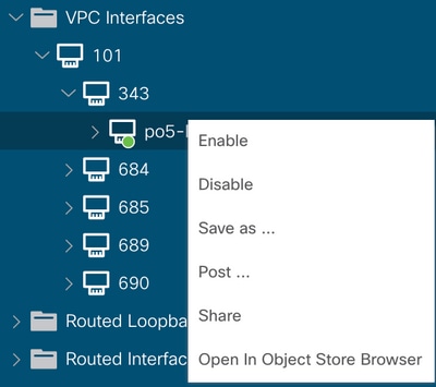
Navigate to:
Fabric -> Inventory -> Pod -> Leaf x -> Interfaces -> VPC interfaces -> vpc -> Port-channel interface where is included the physical port 1/x -> right-click and select Disable.
Then wait 10 seconds, right-click, and selectEnable.

These steps must be performed on the affected interface to force the port-channel synchronization with the peer device and after this process must work properly.
Interface Change to Operational Down
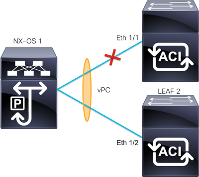
On the APIC GUI, you must see this fault:
Fault F1296: A vPC interface goes down while peer interface is also down.

This example illustrates how the information must be displayed by the interface:
Leaf1# show interface port-channel 5
port-channel5 is down (port-channel-members-down)
admin state is up
Hardware: Port-Channel, address: xxxx.xxxx.xx01 (bia xxxx.xxxx.xx01)
MTU 9000 bytes, BW 100000000 Kbit, DLY 1 usec
reliability 255/255, txload 1/255, rxload 1/255
Encapsulation ARPA, medium is broadcast
Port mode is trunk
full-duplex, 100 Gb/s
Input flow-control is off, output flow-control is off
Auto-mdix is turned on
EtherType is 0x8100
Members in this channel: eth1/1
You must review and discard these topics:
- Physical issues (transceivers and cables) must be the first step in order to review.
- Changes on the configuration for both ends.
- Link Aggregation Control Protocol (LACP) information was received on the Leaf interface.
LACP Logs
You can use the commandshow lacp internal event-history interface ethernet 1/xto obtain the events related to the LACP status like this example:
Leaf1#show lacp internal event-history interface ethernet 1/1

Output omitted
...

9) FSM:<Ethernet1/1> Transition at 2022-07-15T08:43:06.121732000+00:00
Previous state: [LACP_ST_DETACHED_LAG_NOT_DETERMINED]
Triggered event: [LACP_EV_RECEIVE_PARTNER_PDU_TIMED_OUT_II_INDIVIDUAL]
Next state: [LACP_ST_INDIVIDUAL_OR_DEFAULT]

Output omitted
...

18) FSM:<Ethernet1/1> Transition at 2022-07-15T08:46:24.298022000+00:00
Previous state: [LACP_ST_DETACHED_LAG_NOT_DETERMINED]
Triggered event: [LACP_EV_RECEIVE_PARTNER_PDU_TIMED_OUT]
Next state: [FSM_ST_NO_CHANGE]

Output omitted
...

23) FSM:<Ethernet1/1> Transition at 2022-07-15T08:46:27.299819000+00:00
Previous state: [LACP_ST_DETACHED_LAG_NOT_DETERMINED]
Triggered event: [LACP_EV_RECEIVE_PARTNER_PDU_TIMED_OUT_II_INDIVIDUAL]
Next state: [LACP_ST_INDIVIDUAL_OR_DEFAULT]

Output omitted
...

24) FSM:<Ethernet1/1> Transition at 2022-07-15T08:52:25.204611000+00:00
Previous state: [LACP_ST_INDIVIDUAL_OR_DEFAULT]
Triggered event: [LACP_EV_LACP_DOWN_OR_PORT_DOWN]
Next state: [LACP_ST_PORT_IS_DOWN_OR_LACP_IS_DISABLED]
The example logs show that ACI does not receive the proper reply from the peer device, in some cases the peer does not send the PDU/LACP before the keep-alive timer expires.
Next Step:
Now you need to verify the configuration and the status of the peer device.
The Cisco CLI Analyzer (registered customers only) supports certain show commands. Use the Cisco CLI Analyzer in order to view an analysis of the show command output.
Note: Refer to Important Information on Debug Commands before you use debug commands.
Related Information
Revision History
| Revision | Publish Date | Comments |
|---|---|---|
1.0 |
17-Oct-2022 |
Initial Release |
Contributed by Cisco Engineers
- Yosef GarciaTechnical Consulting Engineer
- TAC Engineers
Contact Cisco
- Open a Support Case

- (Requires a Cisco Service Contract)
 Feedback