Configure In-Band Management in ACI
Available Languages
Introduction
This document describes the configuration of In-Band (INB) management in Application Centric Infrastructure (ACI).
Prerequisites
Requirements
Cisco recommends that you have knowledge of these topics:
* Understanding of ACI Access Policies
* Understanding of ACI Contracts
* Understanding of L3out External Network Instance Profile (External EPG) Configuration
Fabric discovery needs to be completed before configuring INB in ACI.
Components Used
The information in this document is based on these software and hardware versions:
- Application Policy Infrastructure Controller (APIC)
- Browser
- ACI running 5.2 (8e)
The information in this document was created from the devices in a specific lab environment. All of the devices used in this document started with a cleared (default) configuration. If your network is live, ensure that you understand the potential impact of any command.
Configure
Configuration is divided into three major steps:
1. Configure the VLAN of INB on the port connecting Leaf and APIC
2. Associate INB EPG in management tenant and assign INB address to all devices.
3. Leak INB address via L3out or Tenant VRF.
Network Diagram
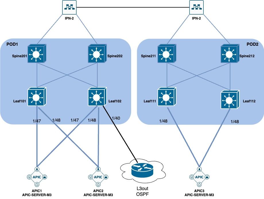
1. Configure the VLAN of INB in the Leaf Interface
1.1. Create a VLAN Pool
Navigate to the APIC web GUI path; Fabric > Access Policies > Pools > VLAN.
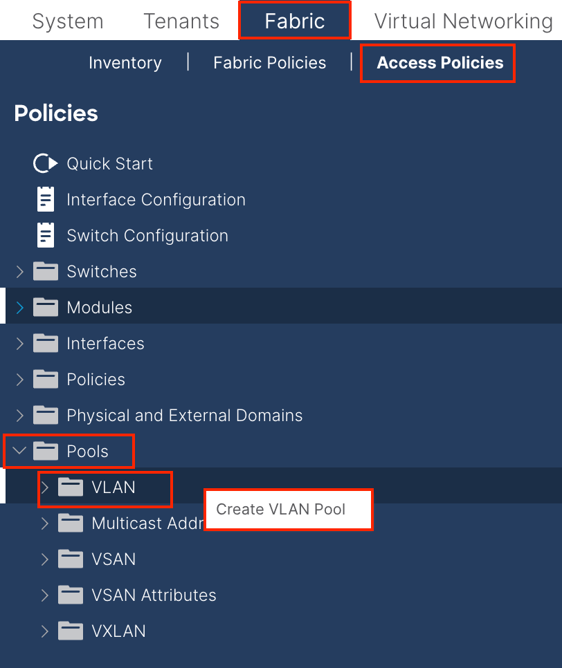
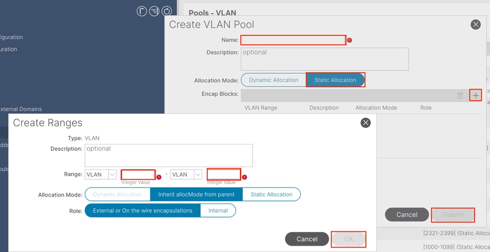
Name - The name of the VLAN Pool. This name can be between 1 and 64 alphanumeric characters.
Description - The description of the VLAN pool. The description can be 0 to 128 alphanumeric characters.
Allocation Mode - The allocation method of this VLAN Pool must be static for INB.
Encap Blocks - The range of assigned VLANs Pool.
Range - The start VLAN ID and the end VLAN ID of the VLAN Pool. The start ID must be less than or equal to the end ID.
1.2. Create Physical Domain
Navigate to the APIC web GUI path; Fabric > Access Policies > Physical and External Domains > Physical Domains.
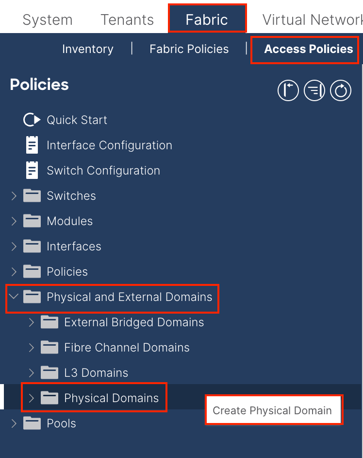
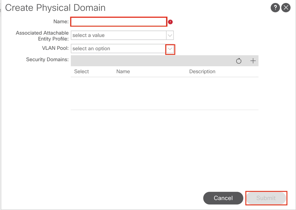
Name - The name of the Physical Domain. This name can be between 1 and 64 alphanumeric characters.
VLAN Pool - Choose the VLAN Pool created in Step 1.1.
1.3. Create Attachable Access Entity Profiles
Navigate to the APIC web GUI path; Fabric > Access Policies > Policies > Global > Attachable Access Entity Profile.
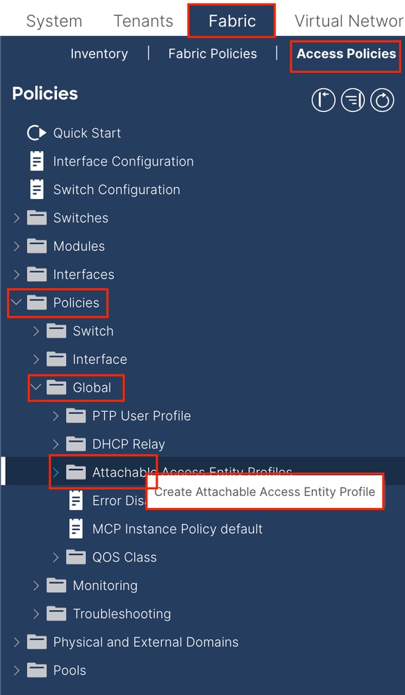

Name - The name of the Attachable Access Entify Profile. This name can be between 1 and 64 alphanumeric characters.
Association to Interfaces - Uncheck. In the final step, manually assign to the interface of Leaf in Step 1.6.
Domains (VMM, Physical or External) to be Associated to Interfaces - Choose the Physical Domain created in Step 1.2.
1.4. Create Leaf Access Port Policy Group
Navigate to the APIC web GUI path; Fabric > Access Policies > Interfaces > Leaf Interfaces > Policy Groups > Leaf Access Port Policy Group.
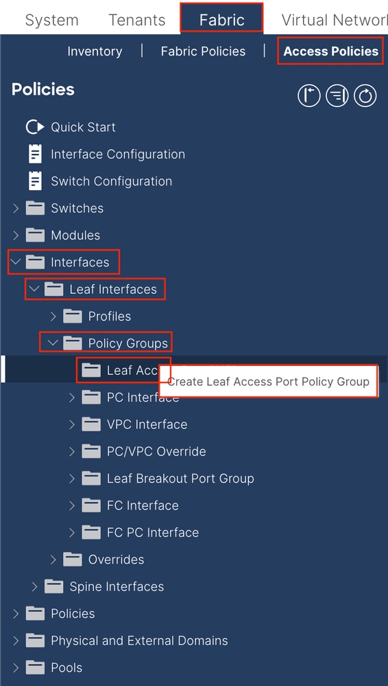
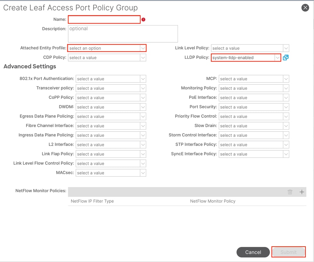
Name - The name of the Leaf Access Port Policy Group. This name can be between 1 and 64 alphanumeric characters.
Attached Entity Profile - Choose the Attached Entity Profile created in Step 1.3.
Link Layer Discovery Protocol (LLDP) Policy - You must choose Enable Policy.
1.5. Create Leaf Access Port Policy Group
Navigate to the APIC web GUI path; Fabric > Access Policies > Interfaces > Leaf Interfaces > Profiles.
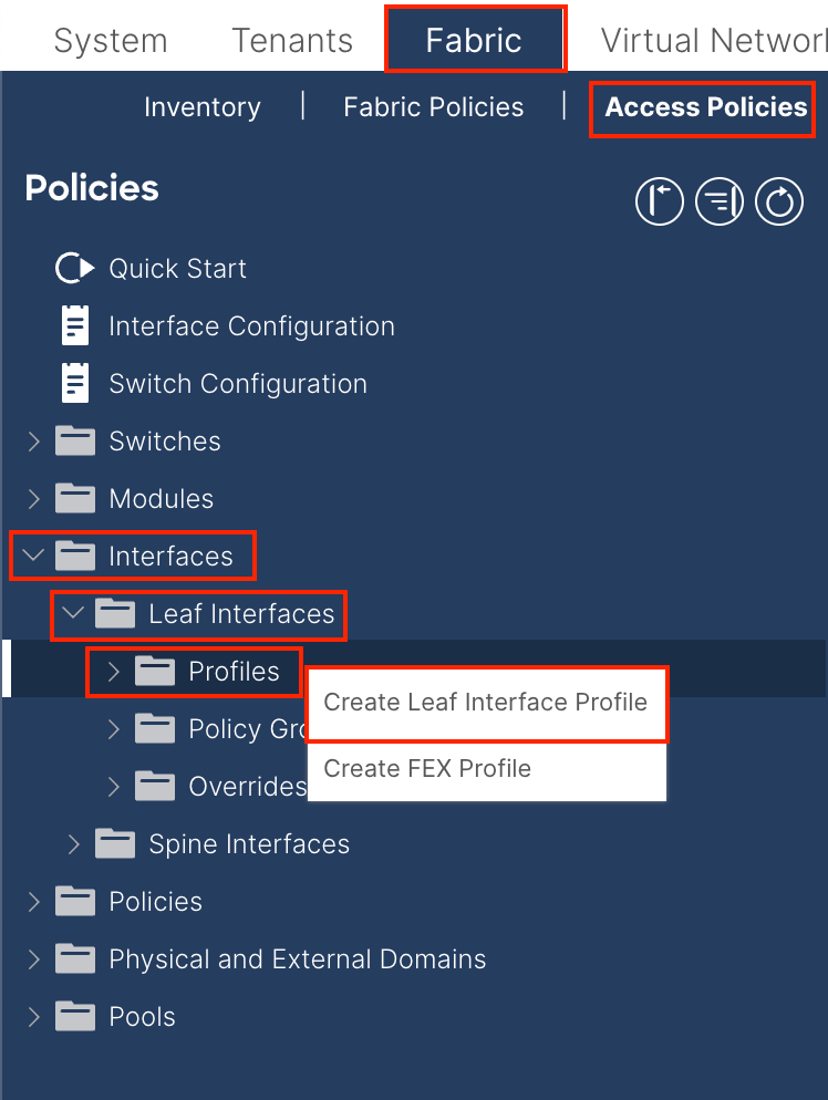
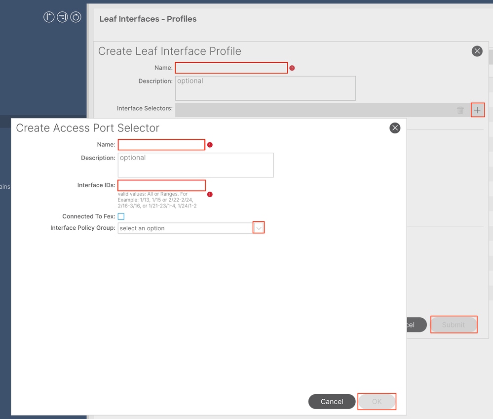
Name - The name of the Leaf Interface Profile. This name can be between 1 and 64 alphanumeric characters.
Interface Selectors - Create a corresponding relationship between interfaces and interface policy.
Name - The name of the Access Port Selector. This name can be between 1 and 64 alphanumeric characters.
Interface IDs - The interface ID is interconnected with APIC. In the document topology, this interface ID is 1/47 or 1/48.
Interface Policy Group - Choose the Attached Entity Profile created in Step 1.4.

Note: In the topology of this document, the interfaces connecting the three APICs to the Leaf are not the same.
Since APIC 3 is not connected to the Eth1/47 interface, the interface IDs of 1/47-1/48 cannot be created.
It is necessary to create separate interface profiles for Eth1/47 and Eth1/48.
1.6. Apply Interface Profile to the Leaf
Navigate to the APIC web GUI path; Fabric > Access Policies > Switches > Leaf Switches > Profiles.
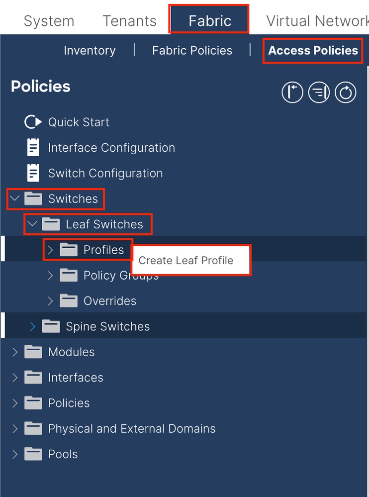
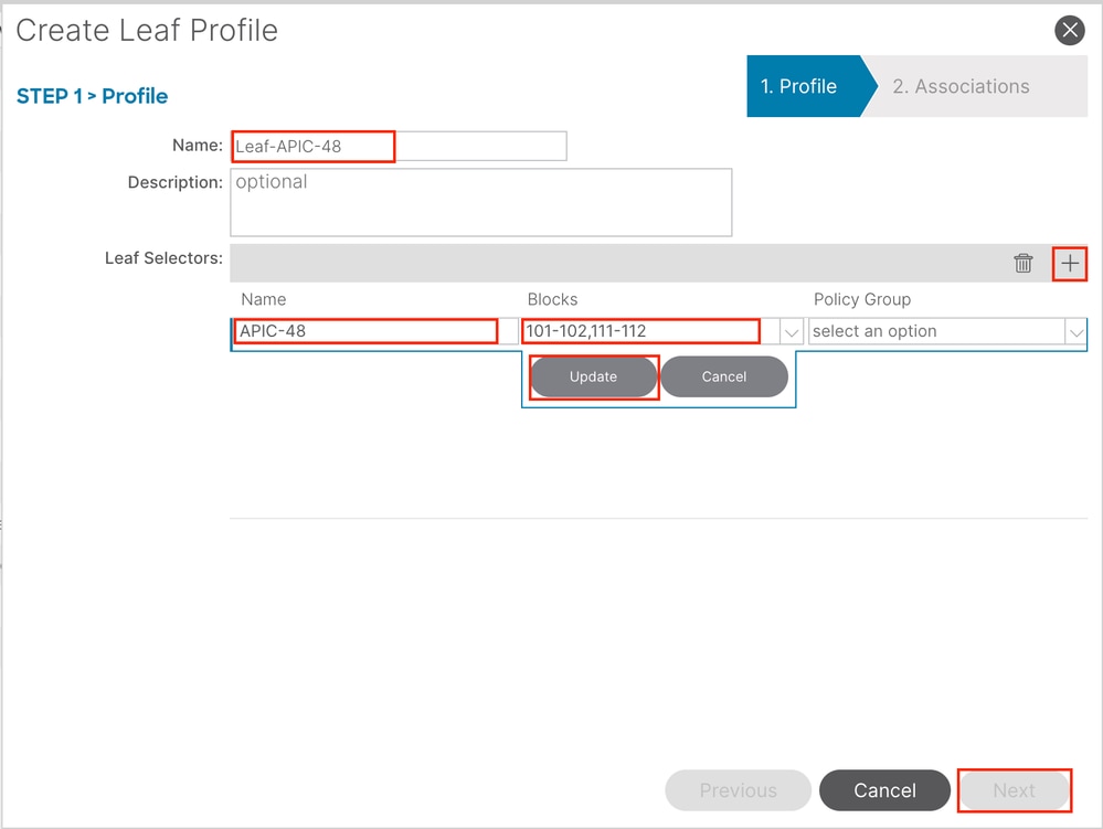
Name - The name of the Leaf Profile. This name can be between 1 and 64 alphanumeric characters.
Leaf Selectors - Choose the Leaf ID to which the interface configuration is pushed.
Name - The name of the Leaf group.
Blocks - Choose the switch node ID.
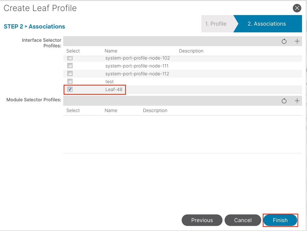
Interface Selector Profiles - Choose the Attached Entity Profile created in Step 1.5.

Note: In this document example, two switch profiles must be configured.
The first one is to choose Leaf 101-102, Leaf 111-112, and assign the interface profile to Eth1/48.
The second is to choose Leaf 111-112 and assign the interface profile to Eth1/47.
For more troubleshooting details about Access Policy, refer to Troubleshoot ACI Access Policies.
2. Assign INB Address in mgmt Tenant
2.1. Create Bridge Domain (BD) INB Subnet
Navigate to the APIC web GUI path; Tenants > mgmt > Networking > Bridge Domains > inb.

Note: This document uses the default BD and default VRF.
You can also create a new VRF and BD in order to perform similar configurations.
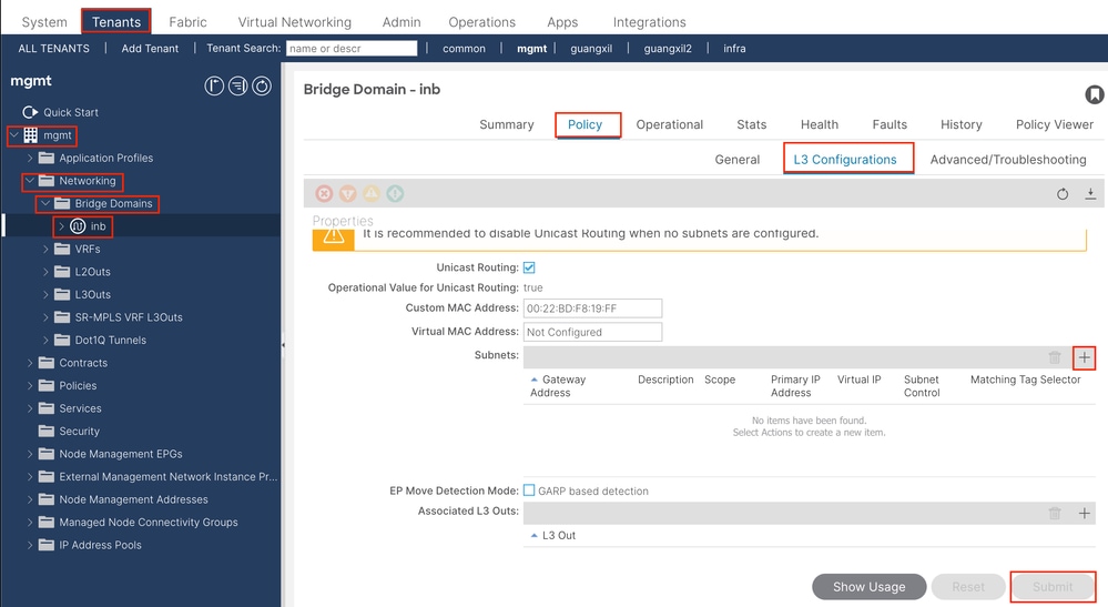
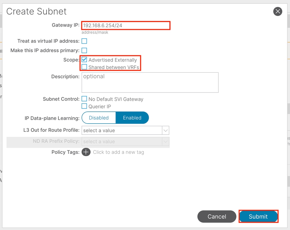
Gateway IP - The INB subnet gateway.
Scope - Choose according to the route leakage method you use. Here choose to use L3out, and then click Advertised Externally.
2.2. Create INB EPG
Navigate to the APIC web GUI path; Tenants > mgmt > Node Management EPGs.
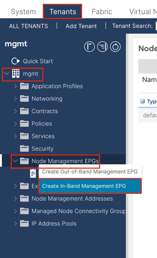
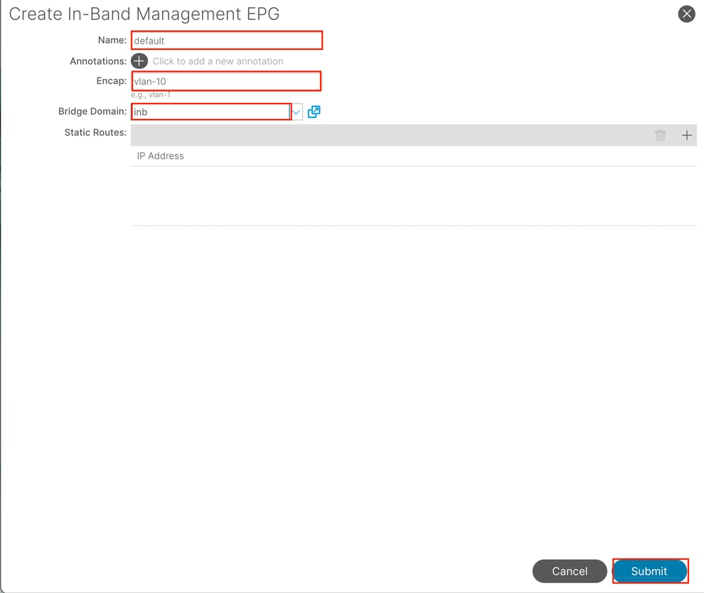
Name - The name of the INB EPG.
Encap - Choose VLAN in the VLAN Pool as you create in Step 1.1.
Bridge Domain - Choose the BD created in Step 2.1.
2.3. Assign Static INB IP Address to the Device
Navigate to the APIC web GUI path; Tenants > mgmt > Node Management Addresses > Static Node Management Addresses.
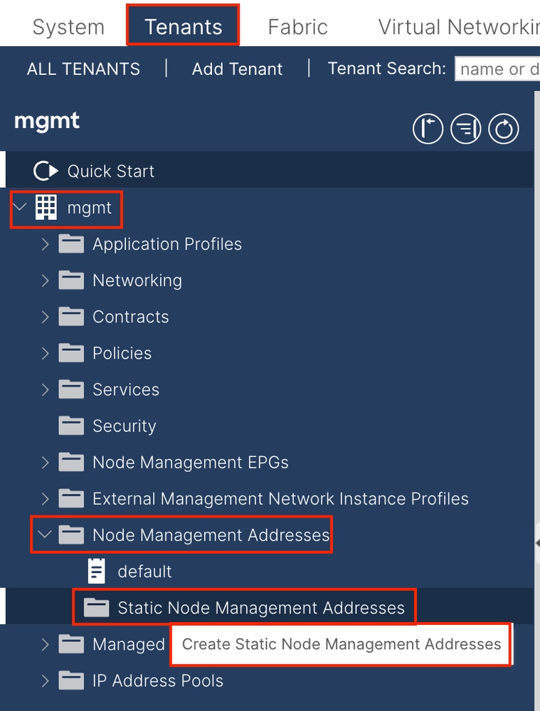
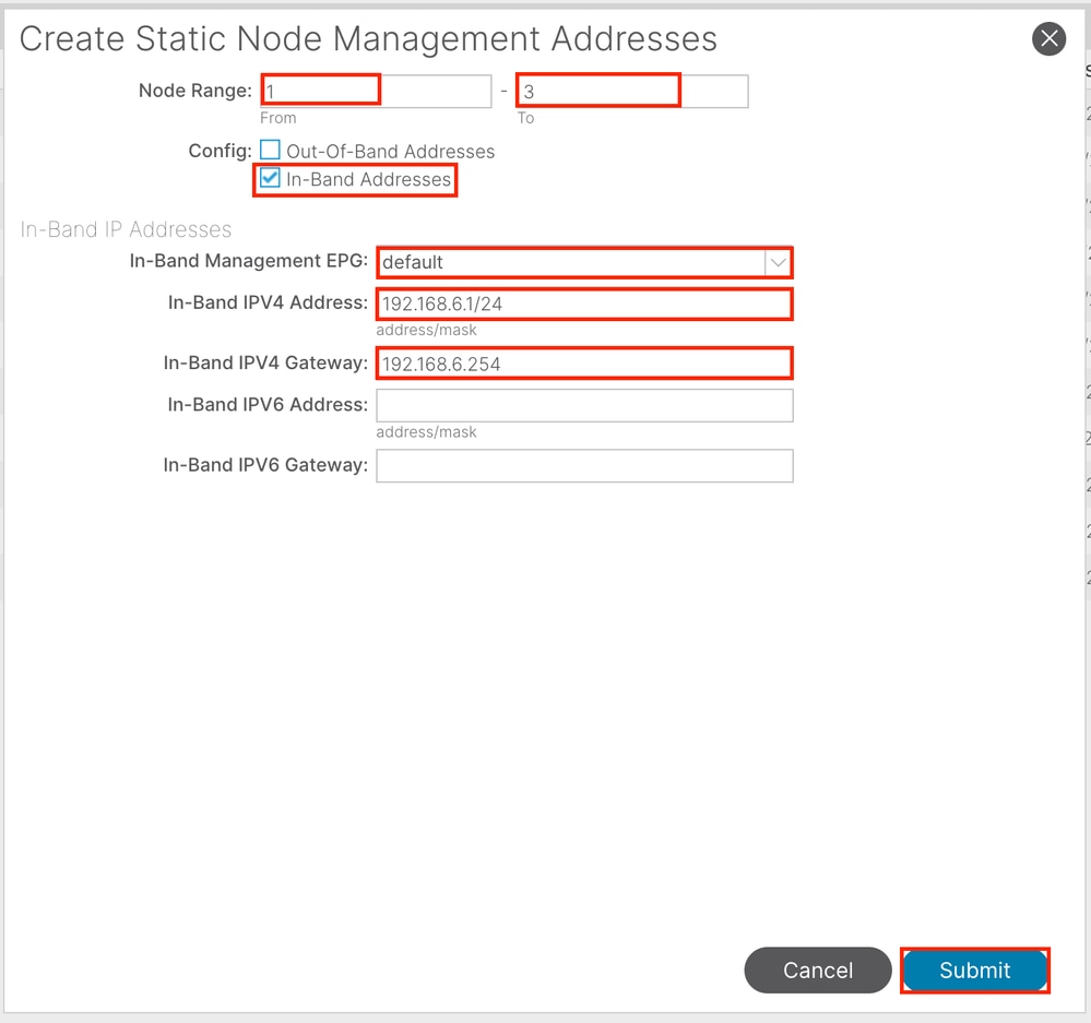
Node Range - The Node ID to be assigned to the INB address. The assigned INB address increases sequentially with the Node ID.
Configuration - Choose In-Band Addresses.
In-Band Management EPG - Choose the EPG created in Step 2.2.
In-Band IPV4 Address - The first assigned INB address.
In-Band IPV4 Gateway - Configure it as the address of the subnet added in Step 2.1.
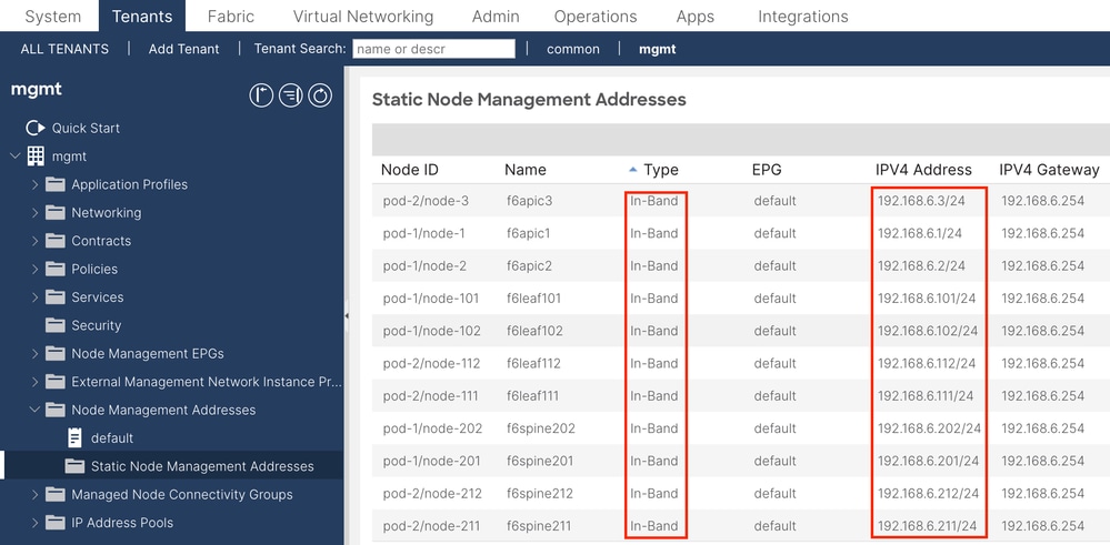

Note: After completing the configuration in Step 2.3., all Leaf and APIC can communicate through INB.
3. Leak INB Address
You can share the INB subnet to other networks through any route leakage method. INB EPG can be regarded as a special EPG. There is no difference with normal EPG when configuring route leakage.
This document only configures L3out as an example.
3.1. Create L3out in mgmt Tenant
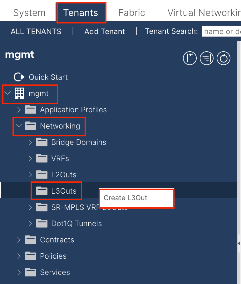
In this example, a physical interface is used with a router running the simple Open Shortest Path First (OSPF) protocol.

Note: If you want to know more details about L3out, refer to the L3out white paper; ACI Fabric L3Out White Paper.
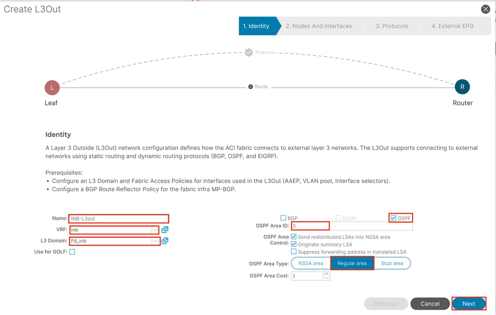
Name - The name of the INB L3out.
VRF - Choose the VRF where the L3out route is located. In this document, the simplest configuration is used, and the VRF INB in the mgmt tenant is selected.
L3 Domain - Create and choose according to the actual situation. For detailed information about L3 Domain, refer to the L3out white paper.
OSPF - In this example, L3out runs the OSPF protocol. Choose a dynamic routing protocol or use static routing according to the actual situation.
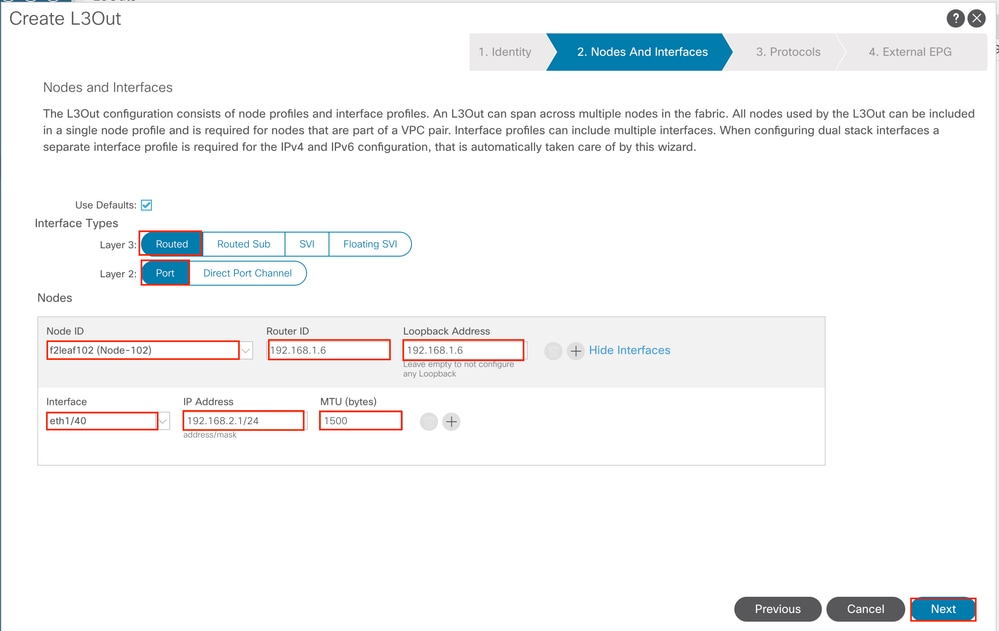
Configure the interface according to your network plan.
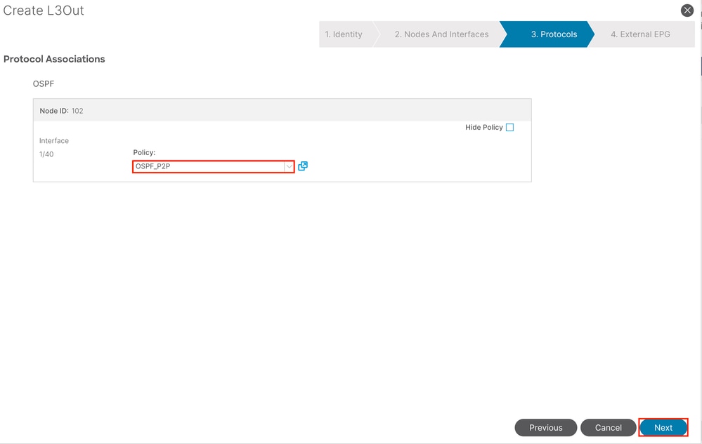
For OSPF, the default network type is broadcast. This example changes the network type to point-to-point.
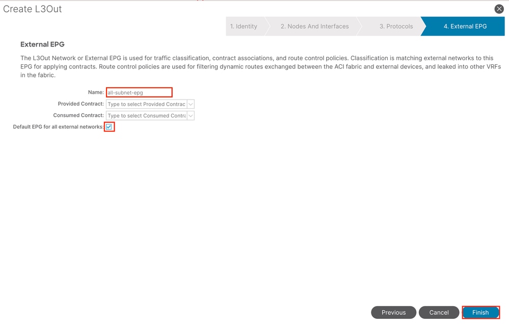
In this example, there is only one L3out and only EPG, and the default Default EPG for all external networks option can be used.

Note: If you have multiple L3out EPGs in the same VRF, configure this option carefully. For more information, refer to the L3out white paper.
After configuring the router, the OSPF neighbor status can change to FULL.
admin-Infra# show lldp neighbors
Capability codes:
  (R) Router, (B) Bridge, (T) Telephone, (C) DOCSIS Cable Device
  (W) WLAN Access Point, (P) Repeater, (S) Station, (O) Other
Device ID            Local Intf      Hold-time  Capability  Port ID
f6leaf102.aci.pub    Eth4/37         120        BR           Eth1/40
admin-Infra# show run

version 8.2(6)

feature ospf
interface loopback66
  vrf member aci-inb
  ip address 192.168.1.7/32
  ip router ospf aci-inb area 0.0.0.0
interface Ethernet4/37
  vrf member aci-inb
  ip address 192.168.2.2/24
  ip ospf network point-to-point
  ip router ospf aci-inb area 0.0.0.0
  no shutdown
vrf context aci-inb
  address-family ipv4 unicast
router ospf aci-inb
  vrf aci-inb
    router-id 192.168.1.7

admin-Infra# show ip ospf neighbors vrf aci-inb
 OSPF Process ID aci-inb VRF aci-inb
 Total number of neighbors: 1
 Neighbor ID     Pri State            Up Time  Address         Interface
 192.168.1.6       1 FULL/ -          00:04:01 192.168.2.1     Eth4/37
admin-Infra#

f6leaf102# show ip int bri vrf mgmt:inb
IP Interface Status for VRF "mgmt:inb"(27)
Interface            Address              Interface Status
eth1/40              192.168.2.1/24       protocol-up/link-up/admin-up
vlan7                192.168.6.254/24     protocol-up/link-up/admin-up
lo37                 192.168.1.6/32       protocol-up/link-up/admin-up
f6leaf102# show ip ospf neighbors vrf mgmt:inb
 OSPF Process ID default VRF mgmt:inb
 Total number of neighbors: 1
 Neighbor ID     Pri State            Up Time  Address         Interface
 192.168.1.7       1 FULL/ -          00:05:08 192.168.2.2     Eth1/40
f6leaf102#
If you need troubleshooting in L3out, refer to Troubleshoot ACI External Forwarding.
3.2. Associated BD to L3out
Navigate to the APIC web GUI path; Tenants > mgmt > Networking > Bridge Domains > inb.
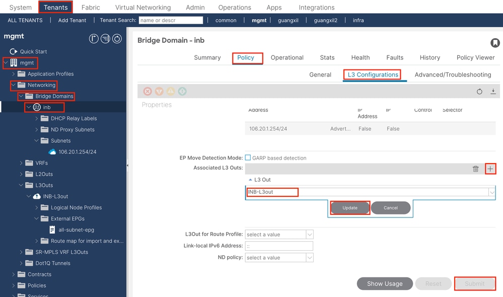
Associated L3outs - Choose the name of the mgmt L3out created in Step 3.1.
3.3. Create Contracts
Navigate to the APIC web GUI path; Tenants > mgmt > Contracts > Standard.
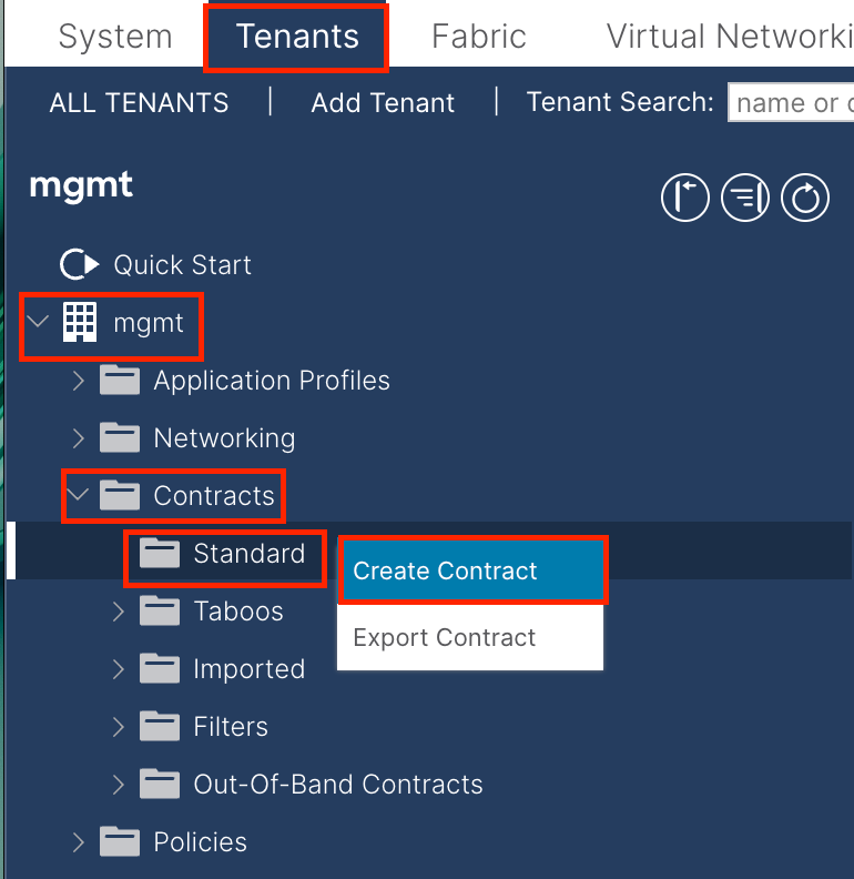
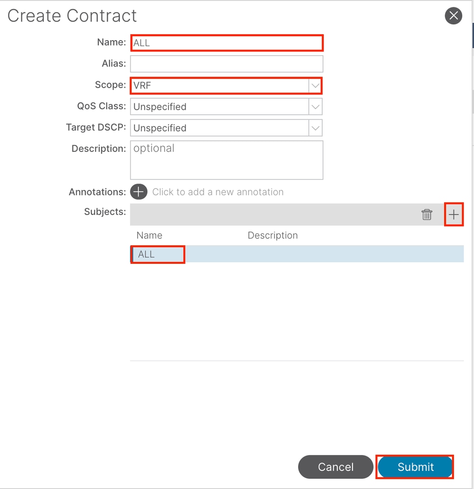

In this example, the contract allows all traffic. If you need more details about the contract, refer to the contract white paper; Cisco ACI Contract Guide White Paper.
3.4. Apply Contract to INB EPG
Navigate to the APIC web GUI path; Tenants > mgmt > Node Management EPGs > In-Band EPG - default.
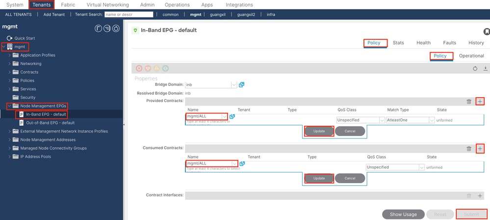
Provided Contracts - Choose the contract created in Step 3.3.
Consumed Contracts - Choose the contract created in Step 3.3.
3.5. Apply Contract to L3out EPG
Navigate to the APIC web GUI path; Tenants > mgmt > Networking > L3Outs > INB-L3out > External EPGs > all-subnet-epg.
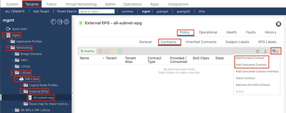
Add Provided Contracts - The contract created in Step 3.3.
Add Consumed Contracts - The contract created in Step 3.3.
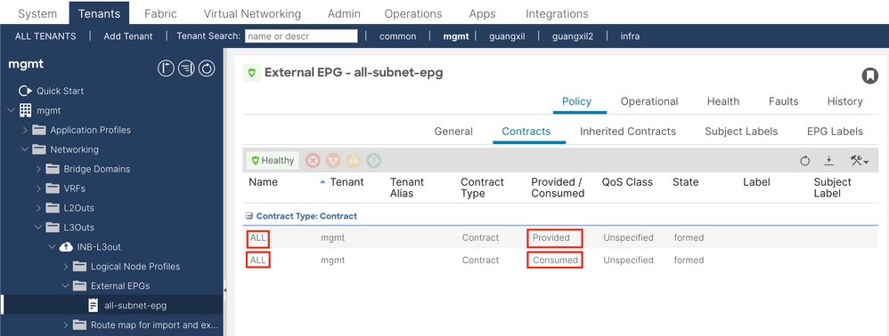
After apply it, you can see the contract in Provided and Consumed.
Verify
You can see the INB route in the External Router.
admin-Infra# show ip route vrf aci-inb
IP Route Table for VRF "aci-inb"
'*' denotes best ucast next-hop
'**' denotes best mcast next-hop
'[x/y]' denotes [preference/metric]
'%<string>' in via output denotes VRF <string>

192.168.1.6/32, ubest/mbest: 1/0
    *via 192.168.2.1, Eth4/37, [110/5], 00:37:40, ospf-aci-inb, intra
192.168.1.7/32, ubest/mbest: 2/0, attached
    *via 192.168.1.7, Lo66, [0/0], 00:04:06, local
    *via 192.168.1.7, Lo66, [0/0], 00:04:06, direct
192.168.2.0/24, ubest/mbest: 1/0, attached
    *via 192.168.2.2, Eth4/37, [0/0], 00:37:51, direct
192.168.2.2/32, ubest/mbest: 1/0, attached
    *via 192.168.2.2, Eth4/37, [0/0], 00:37:51, local
192.168.6.0/24, ubest/mbest: 1/0
    *via 192.168.2.1, Eth4/37, [110/20], 00:24:38, ospf-aci-inb, type-2
admin-Infra#
admin-Infra# ping 192.168.6.1 vrf aci-inb
PING 192.168.6.1 (192.168.6.1): 56 data bytes
64 bytes from 192.168.6.1: icmp_seq=0 ttl=62 time=0.608 ms
64 bytes from 192.168.6.1: icmp_seq=1 ttl=62 time=0.55 ms
64 bytes from 192.168.6.1: icmp_seq=2 ttl=62 time=0.452 ms
64 bytes from 192.168.6.1: icmp_seq=3 ttl=62 time=0.495 ms
64 bytes from 192.168.6.1: icmp_seq=4 ttl=62 time=0.468 ms

--- 192.168.6.1 ping statistics ---
5 packets transmitted, 5 packets received, 0.00% packet loss
round-trip min/avg/max = 0.452/0.514/0.608 ms
admin-Infra# ping 192.168.6.3 vrf aci-inb
PING 192.168.6.3 (192.168.6.3): 56 data bytes
64 bytes from 192.168.6.3: icmp_seq=0 ttl=61 time=0.731 ms
64 bytes from 192.168.6.3: icmp_seq=1 ttl=61 time=0.5 ms
64 bytes from 192.168.6.3: icmp_seq=2 ttl=61 time=0.489 ms
64 bytes from 192.168.6.3: icmp_seq=3 ttl=61 time=0.508 ms
64 bytes from 192.168.6.3: icmp_seq=4 ttl=61 time=0.485 ms

--- 192.168.6.3 ping statistics ---
5 packets transmitted, 5 packets received, 0.00% packet loss
round-trip min/avg/max = 0.485/0.542/0.731 ms
admin-Infra# ping 192.168.6.201 vrf aci-inb
PING 192.168.6.201 (192.168.6.201): 56 data bytes
64 bytes from 192.168.6.201: icmp_seq=0 ttl=63 time=0.765 ms
64 bytes from 192.168.6.201: icmp_seq=1 ttl=63 time=0.507 ms
64 bytes from 192.168.6.201: icmp_seq=2 ttl=63 time=0.458 ms
64 bytes from 192.168.6.201: icmp_seq=3 ttl=63 time=0.457 ms
64 bytes from 192.168.6.201: icmp_seq=4 ttl=63 time=0.469 ms

--- 192.168.6.201 ping statistics ---
5 packets transmitted, 5 packets received, 0.00% packet loss
round-trip min/avg/max = 0.457/0.531/0.765 ms
admin-Infra# ping 192.168.6.211 vrf aci-inb
PING 192.168.6.211 (192.168.6.211): 56 data bytes
64 bytes from 192.168.6.211: icmp_seq=0 ttl=63 time=0.814 ms
64 bytes from 192.168.6.211: icmp_seq=1 ttl=63 time=0.525 ms
64 bytes from 192.168.6.211: icmp_seq=2 ttl=63 time=0.533 ms
64 bytes from 192.168.6.211: icmp_seq=3 ttl=63 time=0.502 ms
64 bytes from 192.168.6.211: icmp_seq=4 ttl=63 time=0.492 ms

--- 192.168.6.211 ping statistics ---
5 packets transmitted, 5 packets received, 0.00% packet loss
round-trip min/avg/max = 0.492/0.573/0.814 ms
admin-Infra# 
Note: If your ACI version was old, the spine nodes do not respond to ping on the in-band as they use loopback interfaces for connectivity which do not respond to Address Resolution Protocol (ARP).
When in-band management is set up, the Cisco APIC always prefers in-band for any traffic that is sourced from the Cisco APIC (like TACACS).
OOB is still accessible for hosts that are sending requests to the OOB address specifically.
Troubleshoot
First, you must check if there are any faults with INB.
On Switch:
f6leaf102# show vrf mgmt:inb
 VRF-Name                           VRF-ID State    Reason
 mgmt:inb                               27 Up       --
f6leaf102#
f6leaf102# show ip int bri vrf mgmt:inb
IP Interface Status for VRF "mgmt:inb"(27)
Interface            Address              Interface Status
eth1/40              192.168.2.1/24       protocol-up/link-up/admin-up
vlan7                192.168.6.254/24     protocol-up/link-up/admin-up
lo37                 192.168.1.6/32       protocol-up/link-up/admin-up

f6leaf102#
f6leaf102# show ip route vrf mgmt:inb
IP Route Table for VRF "mgmt:inb"
'*' denotes best ucast next-hop
'**' denotes best mcast next-hop
'[x/y]' denotes [preference/metric]
'%<string>' in via output denotes VRF <string>

192.168.1.6/32, ubest/mbest: 2/0, attached, direct
    *via 192.168.1.6, lo37, [0/0], 02:12:38, local, local
    *via 192.168.1.6, lo37, [0/0], 02:12:38, direct
192.168.1.7/32, ubest/mbest: 1/0
    *via 192.168.2.2, eth1/40, [110/5], 00:03:09, ospf-default, intra
192.168.2.0/24, ubest/mbest: 1/0, attached, direct
    *via 192.168.2.1, eth1/40, [0/0], 00:37:13, direct
192.168.2.1/32, ubest/mbest: 1/0, attached
    *via 192.168.2.1, eth1/40, [0/0], 00:37:13, local, local
192.168.6.0/24, ubest/mbest: 1/0, attached, direct, pervasive
    *via 192.168.224.64%overlay-1, [1/0], 00:24:06, static
192.168.6.102/32, ubest/mbest: 1/0, attached
    *via 192.168.6.102, vlan7, [0/0], 00:21:38, local, local
192.168.6.254/32, ubest/mbest: 1/0, attached, pervasive
    *via 192.168.6.254, vlan7, [0/0], 00:21:38, local, local
f6leaf102#
On APIC:
f6apic1# ifconfig
bond0.10: flags=4163<UP,BROADCAST,RUNNING,MULTICAST>  mtu 1496
        inet 192.168.6.1  netmask 255.255.255.0  broadcast 192.168.6.255
        inet6 fe80::2ef8:9bff:fee8:8a10  prefixlen 64  scopeid 0x20<link>
        ether 2c:f8:9b:e8:8a:10  txqueuelen 1000  (Ethernet)
        RX packets 37  bytes 1892 (1.8 KiB)
        RX errors 0  dropped 0  overruns 0  frame 0
        TX packets 889  bytes 57990 (56.6 KiB)
        TX errors 0  dropped 0 overruns 0  carrier 0  collisions 0

f6apic1# show inband-mgmt
Table1 : INB-Mgmt Node Details


 Type          Node ID     IP Address            Gateway               Inband EPG            Oper State
 ------------  ----------  --------------------  --------------------  --------------------  --------------------
 f6apic1       1           192.168.6.1/24        192.168.6.254         default               up
 f6apic2       2           192.168.6.2/24        192.168.6.254         default               up
 f6apic3       3           192.168.6.3/24        192.168.6.254         default               up
 f6leaf101     101         192.168.6.101/24      192.168.6.254         default               up
 f6leaf102     102         192.168.6.102/24      192.168.6.254         default               up
 f6leaf111     111         192.168.6.111/24      192.168.6.254         default               up
 f6leaf112     112         192.168.6.112/24      192.168.6.254         default               up
 f6spine201    201         192.168.6.201/24      192.168.6.254         default               up
 f6spine202    202         192.168.6.202/24      192.168.6.254         default               up
 f6spine211    211         192.168.6.211/24      192.168.6.254         default               up
 f6spine212    212         192.168.6.212/24      192.168.6.254         default               up

Table2 : InB-Mgmt EPG Details


 Name             Qos              Tag              Nodes       Vlan        Oper State
 ---------------  ---------------  ---------------  ----------  ----------  ----------
 default          unspecified      32778            1           vlan-10     up
 default          unspecified      32778            2           vlan-10     up
 default          unspecified      32778            3           vlan-10     up
 default          unspecified      32778            101         vlan-10     up
 default          unspecified      32778            102         vlan-10     up
 default          unspecified      32778            111         vlan-10     up
 default          unspecified      32778            112         vlan-10     up
 default          unspecified      32778            201         vlan-10     up
 default          unspecified      32778            202         vlan-10     up
 default          unspecified      32778            211         vlan-10     up
 default          unspecified      32778            212         vlan-10     up

Table3 : INB-Mgmt EPG Contract Details


 INBAND-MGMT-EPG  Contracts        App Epg                    L3 External Epg            Oper State
 ---------------  ---------------  -------------------------  -------------------------  ----------
 default(P)       ALL              default                    all-subnet-epg             up
 default(C)       ALL              default                    all-subnet-epg             up

f6apic1#
f6apic1# bash
admin@f6apic1:~> ip route show
default via 192.168.6.254 dev bond0.10 metric 32
192.168.6.0/24 dev bond0.10 proto kernel scope link src 192.168.6.1
192.168.6.254 dev bond0.10 scope link src 192.168.6.1
admin@f6apic1:~> route -n
Kernel IP routing table
0.0.0.0         192.168.6.254   0.0.0.0         UG    32     0        0 bond0.10
192.168.6.0     0.0.0.0         255.255.255.0   U     0      0        0 bond0.10
192.168.6.254   0.0.0.0         255.255.255.255 UH    0      0        0 bond0.10

admin@f6apic1:~> 
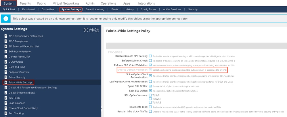
Note: This Enforce Domain Validation function checks the VLAN/Domain and interface configuration used by EPG. If it is not enabled, Leaf ignores the Domain check when pushing the configuration.
Once this feature is enabled, it cannot be disabled. It is recommended to turn this option on in order to avoid incomplete configuration.
Related Information
- Cisco ACI In-Band Management Configuration for Hardware Flow Telemetry Export
- Troubleshoot ACI External Forwarding
- Troubleshoot ACI L3Out - Subnet 0.0.0.0/0 and System PcTag 15
- Troubleshooting Unexpected Route Leaking in ACI
- Troubleshoot ACI Access Policies
- ACI Fabric L3Out White Paper
- Cisco ACI Contract Guide White Paper
- Cisco Technical Support & Downloads
Revision History
| Revision | Publish Date | Comments |
|---|---|---|
1.0 |
08-May-2024 |
Initial Release |
Contact Cisco
- Open a Support Case

- (Requires a Cisco Service Contract)
 Feedback