CSR1000v HA Redundancy Deployment Guide on Amazon AWS
Available Languages
Download Options
Bias-Free Language
The documentation set for this product strives to use bias-free language. For the purposes of this documentation set, bias-free is defined as language that does not imply discrimination based on age, disability, gender, racial identity, ethnic identity, sexual orientation, socioeconomic status, and intersectionality. Exceptions may be present in the documentation due to language that is hardcoded in the user interfaces of the product software, language used based on RFP documentation, or language that is used by a referenced third-party product. Learn more about how Cisco is using Inclusive Language.
Contents
Introduction
This document describes the configuration guide on how to deploy CSR1000v routers for High Availability on Amazon AWS cloud. It is aimed to give users practical knowledge of HA and the ability to deploy a fully functional testbed.
For more in depth background about AWS and HA, refer to the section.
Prerequisites
Requirements
Cisco recommends that you have knowledge of these topics:
- An Amazon AWS account
- 2 CSR1000v and 1 Linux/Windows AMIs in the same region
- HA version 1 is supported on Cisco IOS-XE® versions 16.5 to 16.9. From 16.11 and on, use HA version 3.
Components Used
The information in this document is based on Cisco IOS-XE® Denali 16.7.1.
The information in this document was created from the devices in a specific lab environment. All of the devices used in this document started with a cleared (default) configuration. If your network is live, ensure that you understand the potential impact of any command.
Goal
In a multiple Availability Zone environment, simulate continuous traffic from the private datacenter (VM) to the internet. Simulate an HA failover and observe that HA succeeds as the routing table switches traffic from CSRHA to CSRHA1's private interface is confirmed.
Topology
Before the configuration starts, it is important to understand the topology and design completely. This helps to troubleshoot any potential issues later on.
There are various scenarios of HA deployment based on the network requirements. For this example, HA redundancy is configured with these settings:
- 1x - Region
- 1x - VPC
- 3x - Availability Zones
- 6x - Network Interfaces/Subnets (3x Public Facing/3x Private Facing)
- 2x - Route Tables ( Public & Private )
- 2x - CSR1000v routers (Cisco IOS-XE® Denali 16.3.1a or later)
- 1x - VM (Linux/Windows)
There are 2x CSR1000v routers in an HA pair, in two different availability zones. Think of each availability zone as a separate datacenter for additional hardware resiliency.
The third zone is a VM, which simulates a device in a private datacenter. For now, internet access is enabled through the public interface on so that you can access and configure the VM. Generally, all normal traffic should flow through the private route table.
Ping the VM's private interface → private route table → CSRHA → 8.8.8.8 for Traffic simulation. In a failover scenario, observe the private route table has switched the route to point to CSRHA1's private interface.
Network Diagram

Terminology
RTB - The route table ID.
CIDR - Destination address for the route to be updated in the route table.
ENI - The network interface ID of the CSR 1000v gigabit interface to which traffic is routed.
For Example, if CSRHA fails then CSRHA1 takes over and updates the route in the AWS route table to point to its own ENI.
REGION - The AWS region of CSR 1000v.
Restrictions
- For private subnets, do not use the IP address 10.0.3.0/24—this is used internally on the Cisco CSR 1000v for High Availability. The Cisco CSR 1000v needs to have public internet accessibility to make REST API calls that change the AWS route table.
- Do not put the CSR1000v's gig1 interface inside a VRF. HA does not work otherwise.
Configuration
The general flow of configuration is to start at the top most encompassing feature (Region/VPC) and move your way down to the most specific (Interface/subnet). However, there is no specific order of configuration. Before you start, it is important to understand the topology first .
Tip: Give names to all your settings (VPC, Interface, Subnet, Route Tables, etc).
Step 1. Choose a Region.
This example uses US West (Oregon).

Step 2. Create a VPC.
- On the AWS Console, navigate to VPC > VPC Dashboard > Start VPC Wizard.

- Choose VPC with a Single Public Subnet.
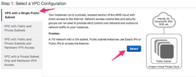
- When you create a VPC, you are assigned a /16 network to use as you please.
- You are also assigned a /24 public subnet. Public subnet instances use Elastic IPs or Public IPs for your devices to access the Internet.

- vpc-b98d8ec0 is created.

Step 3. Create a Security Group for the VPC.
Security Groups are like ACLs to permit or deny traffic.
- Under Security, click on Security Groups and Create your Security Group associated with the above created VPC named HA.

- Under Inbound Rules, define what traffic do you wish to allow for sg-1cf47d6d. For this example, you allow All Traffic.

Step 4. Create an IAM role with a Policy and associate it to the VPC.
IAM grants your CSR access to Amazon APIs.
The CSR1000v is used as a proxy to call AWS API commands to modify the route table. By default, AMI's are not allowed access to APIs. This procedure creates an IAM role and this role is used during the launch of a CSR instance. IAM provides the access credentials for CSRs to use and modify AWS APIs.
- Create IAM role. Browse to the IAM dashboard, and navigate to Roles > Create Role, as shown in the image.

- As shown in the image, allow EC2 instance to call AWS on your behalf.

- Create a Role and click on Next: Review, as shown in the image.

- Give it a Role Name. For this Example, as shown in the image, the Role Name is routetablechange.

- Next, you need to create a policy and attach it to the role you created above. IAM dashboard, and navigate to Policies > Create Policy.

{
"Version": "2012-10-17",
"Statement": [
{
"Effect": "Allow",
"Action": [
"ec2:AssociateRouteTable",
"ec2:CreateRoute",
"ec2:CreateRouteTable",
"ec2:DeleteRoute",
"ec2:DeleteRouteTable",
"ec2:DescribeRouteTables",
"ec2:DescribeVpcs",
"ec2:ReplaceRoute",
"ec2:DisassociateRouteTable",
"ec2:ReplaceRouteTableAssociation"
],
"Resource": "*"
}
]
}
- Give it a policy name and attach it to the Role you created. For this example, the policy name is called CSRHA with Administrator Access, as shown in the image.

- As shown in the image, attach the policy to the role you created called routetablechange.
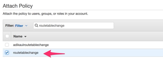
- Summary.

Step 5. Launch the CSR1000v's with the AMI role you Created and Associate the Public/Private Subnets.
Each CSR1000v router has 2 interfaces (1 public, 1 private) and is in its own Availability Zone. You can think of each CSR as being in separate datacenters.
- On AWS console, select EC2 and then click on Launch Instance.

- Select AWS Marketplace.

- Enter CSR1000v and for this example you use Cisco Cloud Services Router (CSR) 1000V - BYOL for Maximum Performance.

- Choose an Instance Type. For this example, the type selected is t2.medium.

- While the Instance is configured, you need to make sure to select the VPC you created above along with the IAM role above. Additionally, create a Private Subnet which you associate to the private facing interface.
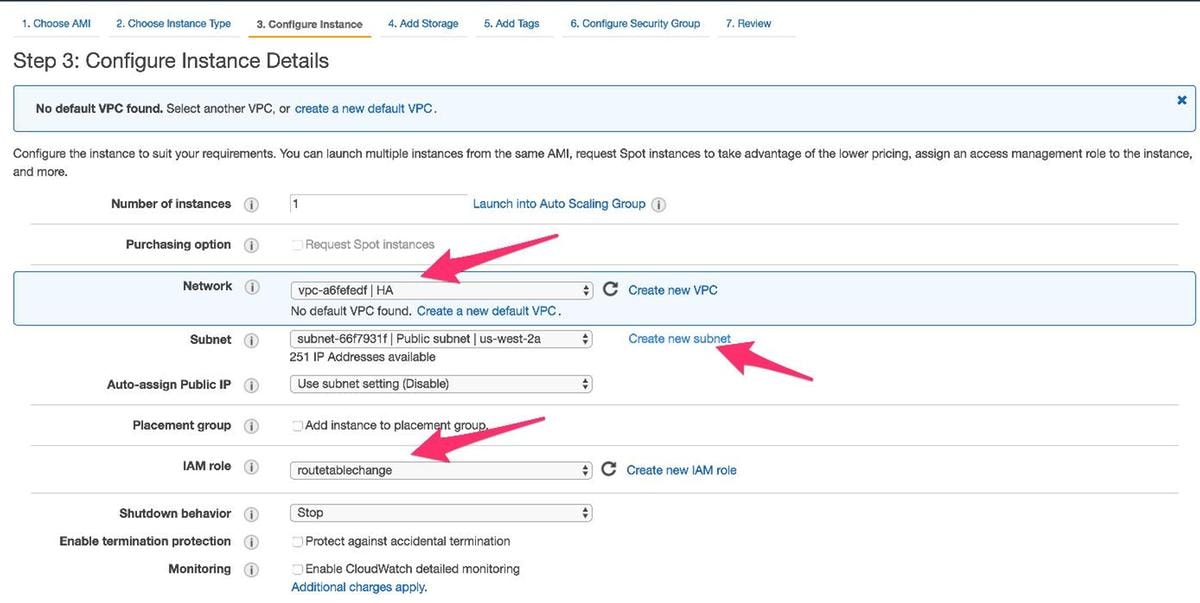
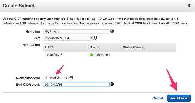
- Click on Create new Subnet for Private Subnet. For this example, the Name tag is HA Private. Ensure that it is in the same Availability Zone as the Public Subnet.
- Scroll down and under Configure Instance Details, click on Add Device, as shown in the image.


- After the secondary interface is added, associate the private subnet you created called HA Private. Eth0 is the public facing and Eth1 is the private facing interface.
Note: The subnet created in the previous step may not appear in this drop down. You may need to refresh or cancel the page and start again for the subnet to appear.

- Select the Security Group you created under VPC and ensure that the rules are properly defined.

- Create a new key pair and ensure to download your private key. You can reuse one key for every device.
Note: If you lose your private key, you cannot login to your CSR's again. There is no method to recover keys.


- Associate the Elastic IP with the ENI of Public Interface for the instance you created and navigate to AWS console > EC2 Management > Network Security > Elastic IP's.
Note: Public/private terminology may confuse you here. For the purposes of this example, definition of a public interface is Eth0 which is the internet facing interface. From the point of view of AWS, our public interface is their private ip.


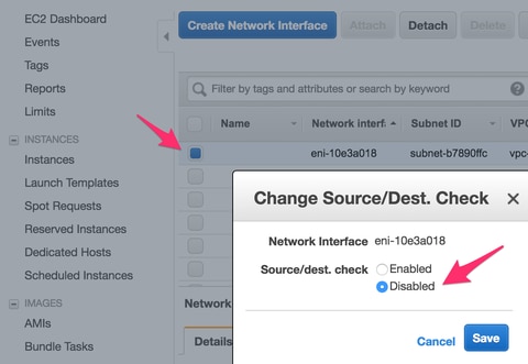
- Disable Source/Dest Check as you navigate to EC2 > Network Interfaces. Verify each ENI for Source/Dest check.
By default, all ENIs come with this Source/Dest check enabled. An anti-spoofing feature meant to avoid letting an ENI get overrun with traffic that is not really intended for it by verifying that the ENI is the destination of the traffic before forwarding it. The router is rarely the actual destination of a packet. This feature must be disabled on all CSR transit ENIs or it cannot forward packets.
- Connect to your CSR1000v.
Note: The username provided by AWS to SSH into the CSR1000v may be incorrectly listed as root. Change this to ec2-user if necessary.
Note: You must be able to ping the DNS address to SSH in. Here it is ec2-54-208-234-64.compute-1.amazonaws.com. Check that the router's public subnet/eni is associated with the Public Route Table. Briefly go to Step 8 on how to associate the subnet to the Route Table.

Step 6. Repeat Step 5 and Create the Second CSR1000v Instance for HA.
Public Subnet: 10.16.1.0/24
Private Subnet: 10.16.5.0/24
If you are unable to ping the elastic ip address of this new AMI, briefly go to Step 8 and ensure that the public subnet is associated with the public route table.
Step 7. Repeat Step 5 and Create a VM(Linux/Windows) from the AMI Marketplace.
For this example, use Ubuntu Server 14.04 LTS on the marketplace.
Public Subnet: 10.16.2.0/24
Private Subnet: 10.16.6.0/24
If you are unable to ping the elastic ip address of this new AMI, briefly go to Step 8 and ensure that the public subnet is associated with the public route table.
- Eth0 is created by default for the public interface. Create a second interface called eth1 for the private subnet.

- The IP address you configure in Ubuntu is the eth1 private interface assigned by AWS.
ubuntu@ip-10-16-2-139:~$ cd /etc/network/interfaces.d/

ubuntu@ip-10-16-2-139:/etc/network/interfaces.d$ sudo vi eth1.cfg

auto eth1
iface eth1 inet static
  address 10.16.6.131
  netmask 255.255.255.0
  network 10.16.6.0
  up route add -host 8.8.8.8 gw 10.16.6.1 dev eth1
- Flap the interface or reboot the VM.
ubuntu@ip-10-16-2-139:/etc/network/interfaces.d$ sudo ifdown eth1 && sudo ifup eth1
ubuntu@ip-10-16-2-139:/etc/network/interfaces.d$ sudo reboot
- Ping 8.8.8.8 for the test. Ensure that the 8.8.8.8 route has been added per step 7.
ubuntu@ip-10-16-2-139:~$ route -n
Kernel IP routing table
Destination Gateway Genmask Flags Metric Ref Use Iface
0.0.0.0 10.16.2.1 0.0.0.0 UG 0 0 0 eth0
8.8.8.8 10.16.6.1 255.255.255.255 UGH 0 0 0 eth1     <--------------
10.16.3.0 0.0.0.0 255.255.255.0 U 0 0 0 eth0
10.16.6.0 0.0.0.0 255.255.255.0 U 0 0 0 eth1
If 8.8.8.8 is not listed in the table, add it manually:
ubuntu@ip-10-16-2-139:~$ sudo route add -host 8.8.8.8 gw 10.16.6.1 dev eth1
Step 8. Configure the Private and Public Route Tables.
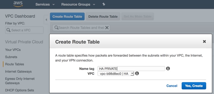
- When a VPC through the wizard in Step 2 is created, two route tables are automatically created. If there is only one Route Table, create another one for your private subnets, as shown in the image.

- Here is a view of the two Route Tables. The PUBLIC Route Table has the Internet Gateway (igw-95377973) automatically attached. Label these two tables accordingly. The PRIVATE table should NOT have this route.

- Associate all 6 subnets to the proper Route Table
3 Public interfaces are associated with the Public Route Table:
Public Subnets: 10.16.0.0/24, 10.16.1.0/24, 10.16.2.0/24
3 Private interfaces are associated with the Private Route Table:
Private Subnets: 10.16.4.0/24, 10.16.5.0/24, 10.16.6.0/24

Step 9. Configure Network Address Transaltion (NAT) and GRE Tunnel with BFD, and any Routing Protocol.
Configure the Generic Routing Encapsulation (GRE) tunnel through the Elastic IPs of the CSR 1000v's (recommended to avoid DHCP lease renewal issues, which detect false failures.) The Biderection Forwarding Detection (BFD) values can be configured to be more aggressive than those shown in this example, if faster convergence is required. However, this can lead to BFD peer down events during intermittent connectivity. The values in this example detects peer failure within 1.5 seconds. There is a variable delay of about a few seconds between the time when the AWS API command is executed and when the VPC routing table changes go into effect.
- Configuration on CSRHA
GRE and BFD - Used to observe conditions for HA failover
interface Tunnel1
  ip address 192.168.1.1 255.255.255.0
  bfd interval 500 min_rx 500 multiplier 3
  tunnel source GigabitEthernet1
  tunnel destination 52.10.183.185 /* Elastic IP of the peer CSR */
!
router eigrp 1
  bfd interface Tunnel1
  network 192.168.1.0
  passive-interface GigabitEthernet1
NAT and Routing - Used for VM internet reachability through the private interface
interface GigabitEthernet1
  ip address dhcp
  ip nat outside
  no shutdown
!
interface GigabitEthernet2
  ip address dhcp
  ip nat inside
  no shutdown
!
ip nat inside source list 10 interface GigabitEthernet1 overload
!
access-list 10 permit 10.16.6.0 0.0.0.255
!
ip route 10.16.6.0 255.255.255.0 GigabitEthernet2 10.16.4.1
- Configuration on CSRHA1
GRE and BFD - Used to observe conditions for HA failover
interface Tunnel1
  ip address 192.168.1.2 255.255.255.0
  bfd interval 500 min_rx 500 multiplier 3
  tunnel source GigabitEthernet1
  tunnel destination 50.112.227.77 /* Elastic IP of the peer CSR */
!
router eigrp 1
  bfd interface Tunnel1
  network 192.168.1.0
  passive-interface GigabitEthernet1
NAT and Routing - Used for VM internet reachability through the private interface
interface GigabitEthernet1
  ip address dhcp
  ip nat outside
  no shutdown
!
interface GigabitEthernet2
  ip address dhcp
  ip nat inside
  no shutdown
!
ip nat inside source list 10 interface GigabitEthernet1 overload
!
access-list 10 permit 10.16.6.0 0.0.0.255
!
ip route 10.16.6.0 255.255.255.0 GigabitEthernet2 10.16.5.1
Step 10. Configure High Availability (Cisco IOS XE Denali 16.3.1a or later).
Monitor BFD peer down events by configuring each CSR 1000v using the cloud provider aws command specified below. Use this command to define the routing changes to (VPC) Route-table-id, Network-interface-id and CIDR after an AWS HA error such as BFD peer down, is detected.
CSR(config)# redundancy
CSR(config-red)# cloud provider [aws | azure] node-id
# bfd peer ipaddr
# route-table table-name
# cidr ip ipaddr/prefix
# eni elastic-network-intf-name
# region region-name
- The #bfd peer ipaddr is the peer Tunnel ip address.
CSRHA#show bfd neighbors

IPv4 Sessions
NeighAddr LD/RD RH/RS State Int
192.168.1.2 4097/4097 Up Up Tu1
- The #route-table table-name is found under AWS console, navigate to VPC > Route Tables. This action alters the Private Route Table.

- The #cidr ip ipaddr/prefix is the destination address for the route to be updated in the route table. Under AWS console, navigate to VPC > Route Tables. Scroll down, click Edit and then on Add another route. Add our test destination address of 8.8.8.8 and CSRHA's private ENI.


- The #eni elastic-network-intf-name is found in your EC2 instance. Click on your Private facing interface eth1 for each of the corresponding CSR's and use the Interface ID.

- The #region name is the code name found in the AWS document. This list may change or grow. To find the latest updates, visit Amazon's Region and Availability Zones document.

Redundancy Configuration Example on CSRHA
redundancy
cloud provider aws 1
  bfd peer 192.168.1.2
  route-table rtb-ec081d94
  cidr ip 8.8.8.8/32
  eni eni-90b500a8
  region us-west-2
Redundancy Configuration Example on CSRHA1
redundancy
cloud provider aws 1
  bfd peer 192.168.1.1
  route-table rtb-ec081d94
  cidr ip 8.8.8.8/32
  eni eni-10e3a018
  region us-west-2
Verify High Availability
- Check BFD and cloud configurations.
CSRHA#show bfd nei

IPv4 Sessions
NeighAddr LD/RD RH/RS State Int
192.168.1.2 4097/4097 Up Up Tu1


CSRHA#show ip eigrp neighbors
EIGRP-IPv4 Neighbors for AS(1)
H Address Interface Hold Uptime SRTT RTO Q Seq
(sec) (ms) Cnt Num
0 192.168.1.2 Tu1 12 00:11:57 1 1470 0 2
CSRHA#show redundancy cloud provider aws 1

Cloud HA: work_in_progress=FALSE
Provider : AWS node 1
State : idle
BFD peer     = 192.168.1.2
BFD intf     = Tunnel1
route-table  = rtb-ec081d94
cidr         = 8.8.8.8/32
eni          = eni-90b500a8
region       = us-west-2
- Run a continuous ping from the VM to the destination. Ensure the ping is through the private eth1 interface.
ubuntu@ip-10-16-3-139:~$ ping -I eth1 8.8.8.8
PING 8.8.8.8 (8.8.8.8) from 10.16.6.131 eth1: 56(84) bytes of data.
64 bytes from 8.8.8.8: icmp_seq=1 ttl=50 time=1.60 ms
64 bytes from 8.8.8.8: icmp_seq=2 ttl=50 time=1.62 ms
64 bytes from 8.8.8.8: icmp_seq=3 ttl=50 time=1.57 ms
- Check the Private Route Table. The eni is currently the private interface of CSRHA where this is the traffic.

- Shut down Tunnel1 of CSRHA to simulate an HA Failover.
CSRHA(config)#int Tun1
CSRHA(config-if)#shut
- Observe that the Route Table points to the new ENI which is the private interface of CSRHA1.

Troubleshoot
- Ensure resources are associated. When creating VPC, Subnets, Interfaces, Route Tables, etc, many of these are not associated with each other automatically. They have no knowledge of each other.
- Ensure that the Elastic IP and any Private IP is associated with the correct Interfaces, with the right subnets, added to the correct Route Table, connected to the correct router and the correct VPC and Zone, linked with the IAM Role and security groups.
- Disable Source/Dest check per ENI.
- For Cisco IOS XE 16.3.1a or later, this is the additional verification commands available.
show redundancy cloud provider [aws | azure] node-id
debug redundancy cloud [all | trace | detail | error]
debug ip http all
- Here are common failures seen in debugs:
Problem: httpc_send_request failed
Resolution: Http is used to send the API call from the CSR to AWS. Ensure DNS can resolve the DNS name listed in your instance. Ensure http traffic is not blocked.
*May 30 20:08:06.922: %VXE_CLOUD_HA-3-FAILED: VXE Cloud HA BFD state transitioned, AWS node 1 event httpc_send_request failed
*May 30 20:08:06.922: CLOUD-HA : AWS node 1 httpc_send_request failed (0x12)
URL=http://ec2.us-east-2b.amazonaws.com
Problem: route table rtb-9c0000f4 and interface eni-32791318 belong to different networks
Resolution: Region name and ENI are incorrectly configured in different networks. Region and ENI should be in the same zone as the router.
*May 30 23:38:09.141: CLOUD-HA : res content iov_len=284 iov_base=<?xml version="1.0" encoding="UTF-8"?>
<Response><Errors><Error><Code>InvalidParameterValue</Code><Message>route table rtb-9c0000f4 and interface eni-32791318 belong to different networks</Message></Error></Errors><RequestID>af3f228c-d5d8-4b23-b22c-f6ad999e70bd</RequestID></Response>
Problem: You are not authorized to perform this operation. Encoded authorization failure message.
Resolution: IAM JSON role/policy created incorrectly or not applied to the CSR. IAM role authorizes the CSR to make API calls.
*May 30 22:22:46.437: CLOUD-HA : res content iov_len=895 iov_base=<?xml version="1.0" encoding="UTF-8"?>
<Response><Errors><Error><Code>UnauthorizedOperation</Code><Message>You are not authorized to perform this operation. Encoded
authorization failure message: qYvEB4MUdOB8m2itSteRgnOuslAaxhAbDph5qGRJkjJbrESajbmF5HWUR-MmHYeRAlpKZ3Jg_y-_tMlYel5l_ws8Jd9q2W8YDXBl3uXQqfW_cjjrgy9jhnGY0nOaNu65aLpfqui8kS_4RPOpm5grRFfo99-8uv_N3mYaBqKFPn3vUcSYKBmxFIIkJKcjY9esOeLIOWDcnYGGu6AGGMoMxWDtk0K8nwk4IjLDcnd2cDXeENS45w1PqzKGPsHv3wD28TS5xRjIrPXYrT18UpV6lLA_09Oh4737VncQKfzbz4tPpnAkoW0mJLQ1vDpPmNvHUpEng8KrGWYNfbfemoDtWqIdABfaLLLmh4saNtnQ_OMBoTi4toBLEb2BNdMkl1UVBIxqTqdFUVRS**MSG 00041 TRUNCATED**
**MSG 00041 CONTINUATION #01**qLosAb5Yx0DrOsLSQwzS95VGvQM_n87LBHYbAWWhqWj3UfP_zmiak7dlm9P41mFCucEB3Cs4FRsFtb-9q44VtyQJaS2sU2nhGe3x4uGEsl7F1pNv5vhVeYOZB3tbOfbV1_Y4trZwYPFgLKgBShZp-WNmUKUJsKc1-6KGqmp7519imvh66JgwgmU9DT_qAZ-jEjkqWjBrxg6krw</Message></Error></Errors><RequestID>4cf31249-2a6e-4414-ae8d-6fb825b0f398</RequestID></Response>
Related Information
-
Cisco CSR 1000v Series Cloud Services Router Deployment Guide for Amazon Web Services
- Instance types breakdown
- EC2 and VPCs
- Elastic Network Interfaces, from EC2 User Guide, includes # of ENIs per instance type
- Enhanced Networking on Linux how-to, useful background info
- Dedicated Instances/tenancy Explanation and How-to
- General EC2 Documentation
- General VPC Documentation
- Regions and Availability Zones
- CSR1000v High Availability version 3
Contributed by Cisco Engineers
- David W ChenCisco TAC Engineer
- Aditya KaulCisco TAC Engineer
Contact Cisco
- Open a Support Case

- (Requires a Cisco Service Contract)
 Feedback