Configure Recorder in CMS/Acano Call Bridge
Available Languages
Download Options
Bias-Free Language
The documentation set for this product strives to use bias-free language. For the purposes of this documentation set, bias-free is defined as language that does not imply discrimination based on age, disability, gender, racial identity, ethnic identity, sexual orientation, socioeconomic status, and intersectionality. Exceptions may be present in the documentation due to language that is hardcoded in the user interfaces of the product software, language used based on RFP documentation, or language that is used by a referenced third-party product. Learn more about how Cisco is using Inclusive Language.
Contents
Introduction
This document describes the configuration steps needed to setup the Recorder on the Call Bridge (CB) component of a Cisco Meeting Server (CMS).
Prerequisites
Requirements
There are no specific requirements for this document.
Components Used
The information in this document is based on these software and hardware versions:
- CMS 1.9 or higher
- Postman from Google Chrome
- CMS Application Program Interface (API)
The information in this document was created from the devices in a specific lab environment. All of the devices used in this document started with a cleared (default) configuration. If your network is live, ensure that you understand the potential impact of any command.
Background Information
The CMS Recorder is available from release 1.9 of the CMS (former Acano) server. The Recorder provides the capability to record meetings and save the recordings on a Network File System (NFS) document storage.
The Recorder behaves like an Extensible Messaging and Presence Protocol (XMPP) client, so the XMPP server must be enabled on the server that hosts the Call Bridge.
Recorder license is needed and must be applied on the CallBridge component, and not on the Recorder server.
Network File System (NFS) directory is needed, and it can be setup on Windows Server or Linux.
- For Windows server, follow the steps to Deploy Network File system on Windows
- For Linux, follow the steps to Deploy Network File system on Linux
Note: For NFS that runs on Windows Server 2008 R2 there is a hotfix for Permission issue.
Deployments
Supported Deployments
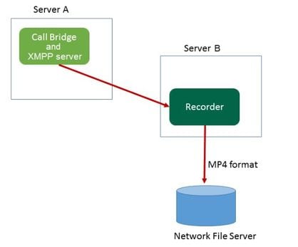
1. The Recorder must be hosted on an CMS/Acano server which is remote to the server that hosts the CB, as shown on this image
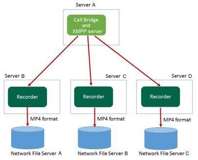
2. Redundant deployment of the Recorder is also supported. If redundancy is setup, the recordings are load balanced between all recording devices (servers). This means that every CB uses every Recorder available, as shown on this image
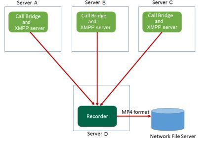
3. The same applies in the opposite, when there are multiple CBs. All the CB nodes use the Recorder available to them, as shown on this image
Other Setup
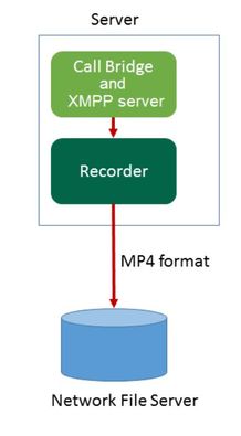
The Recorder can also be hosted on the same server as the CB, but this must only be used for testing or very small deployments, see the next image for reference. The drawback here is that only 1-2 simultaneous recordings are possible:
Configure
Step 1. Configure an NFS Share Folder on a Windows Server
a. Using Windows Explorer, create a new folder for your NFS share. In this example, a folder named Single Split Recordings has been created on my local disk
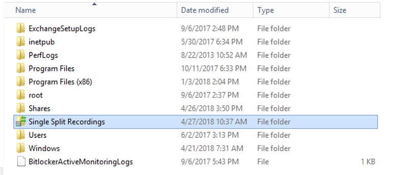
b. Right-click the folder, and select Properties
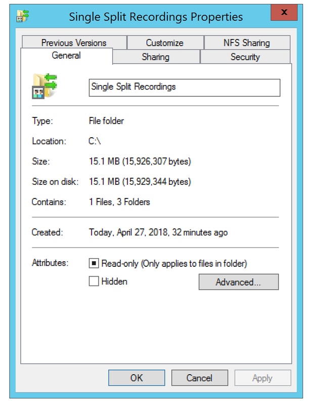
c. Select the NFS Sharing tab at the top-right. It shows the folder as Not shared. In this example, The folder has been previously shared, otherwise you must see a blank network path and the folder is displayed as Not Shared
d. Select Manage NFS Sharing
e. Mark the checkbox next to Share this folder
f. Enter your folder share name in Share name with no space(s)
Note: This is used by the NFS clients and the CMS recorder to find this folder.
Note: Ensure that there is no space(s) in your folder share name. If there are, you would not be able to save your changes and this error Window appears:
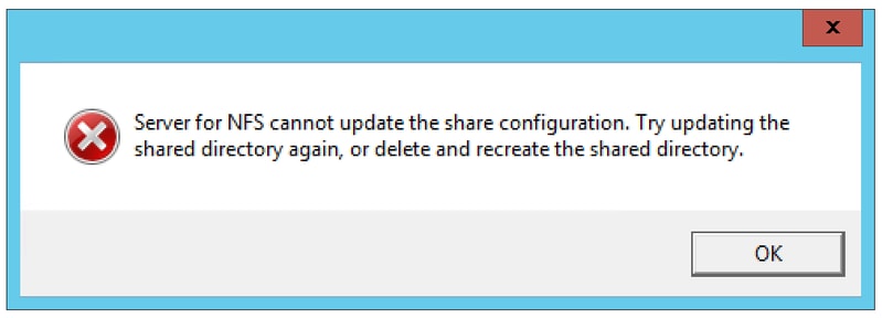
g. Leave the encoding at its default ANSI value
h. By default, all of the authentication checkboxes are marked. Uncheck all of the Kerberos authentication options leaving only the No server authentication [Auth_SYS]
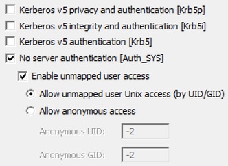
i. Select Allow unmapped user Unix access (by UID/GID)
j. At the bottom, select Permissions to set permissions on the network share
Note: The default is Read-Only for all machines. The recorder must have Read-Write access, so you can change the default for ALL MACHINES, or add specific rules for your recorder. The best practice would be to disable access to ALL MACHINES by changing it to No Access and adding new permission for the IP of the servers that need access to the share.
k. To add permission for your recorder, select Add
l. In Add Names, enter the IP address of your Recorder server. In this example, my recorder server is 10.48.54.75
m. Select Read-Write access
n. Leave Encoding as ANSI
o. Leave Allow root access disabled
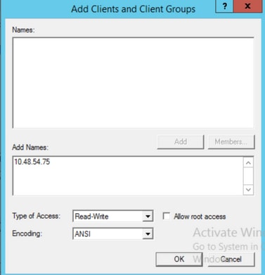
p. Select OK to close the permissions dialog
q. Select ALL MACHINES
r. Change Type of access to No Access
s. Select OK to close the permissions window
t. Select OK again to return to the Folder Properties Window
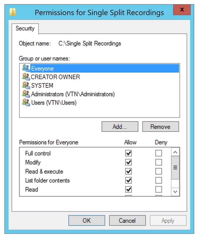
u. Select Security
Note: The Everyone group must have full access to the folder. If it is not listed, select Edit to open the Permissions editor. Select Add to add a user, and in the names field enter Everyone the select OK. Select Everyone on the list, and mark the checkbox for Full control and select OK. Select OK again to close the properties. If configured correctly, it resembles the next image:
Step 2. Configure and enable recorder on the Recorder server
a. Configure the Recorder to listen on the interface(s) of your choice with this command:
recorder listen <interface[:port] whitelist>
b. If the recorder is on the local CB, the interface must be the set to “loopback”, so use this command:
recorder listen lo:8443
c. If it’s to listen on a specific interface, let’s say “a”, then use this:
recorder listen a:8443
Note: If you configure the recorder on a node of clustered CB, the interface must be the local listening interface of the node on which the recorder is being configured.
d. Set the certificate file to be used by the recorder. You can use a certificate that already exists and private key file used by the CB, for example.
recorder certs <keyfile> <certificate file>
e. Add the CB certificate to the Recorder trust store using the command:
recorder trust <crt-bundle>
The crt-bundle must contain the certificate used by the CB, if different. If in a cluster, this must contain the certificates of every CB in the cluster.
f. Specify the hostname or IP address of the NFS, and the directory on the NFS to Store the recordings:
recorder nfs <hostname/IP>:<directory>
Note: The Recorder does not authenticate to the NFS but it’s important that the Recorder Server has read/write access to the NFS directory.
g. Enable the Recorder, with the use of the command:
recorder enable
Step 3. Create an API user on the CB
Create an API user on the CB, this is required for further configurations using the API function:
Create the user with these steps:
a. Connect via Secure Shell (SSH) or console to the CB with the use of the admin credentials.
b. User add <username> api, then press the Return key and enter the password followed by the Return Key.
Step 4. Add the Recorder onto the CB using the API
1. Download and Install Postman from here
2. Enter the API access URL in the address bar, for example: https://<Callbridge_IP>:445/api/v1/<entity>. Then, set in authentication, the username and password from Step 3, under Authorization with Basic Auth as type
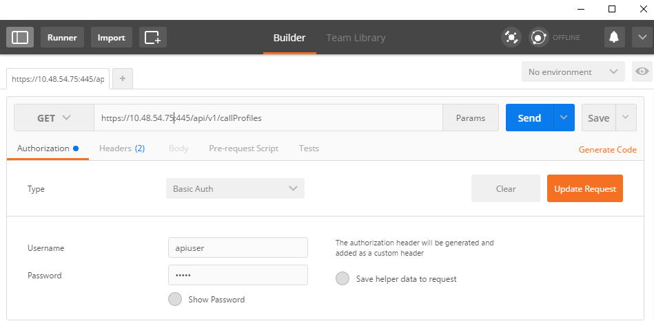
Note: This assumes that there's currently no recorder or callProfile configured on the CB. Otherwise you can modify a recorder that exists and/or callProfile with the use of the PUT method.
3. Add the recorder to the CB with the API
a. Send an empty POST with https://<Callbridge_IP>:445/api/v1/recorders
b. Send a GET with the same URL in (a), copy the recorder ID, without the quotes to Notepad
c. Set the URL of the recorder by sending a PUT with https://<Callbridge_IP>:445/api/v1/recorders/<recorderid> and add this in BODY before you execute the PUT:
url=https://127.0.0.1:8443 (if the recorder is on the local CB)
or
url=https://<IP Address of recorder>:8443 (if the recorder is not on the local CB)
For example:

Note: dtmfProfile, callProfile and callLegProfile are particularly important for SIP endpoints that join a cospace conference. They allow the Endpoint to be able to start/stop the recording of a call to/from the cospace.
As from CMA 1.9.3 and CMS 2.0.1, the DTMF tones are not required now there is the  button that's added to the client when the recorder is present on or known to the callbridge to which the client is connected. The record button has been added to WebRTC from CMS 2.3 as well.
4. Create a callProfile
a. Send an empty POST with https://<Callbridge_IP>:445/api/v1/callProfiles
b. Send a GET with the same URL in (a), copy the callProfile ID, without the quotes to Notepad
c. Set the recordingMode on the callProfile by sending a PUT with https://<Callbridge_IP>:445/api/v1/callProfiles/<call profile ID> and add the in BODY before you execute the PUT.
recordingMode=Manual (if you want callers to start recording using DTMF entries)
or
recordingMode=Automatic (if recording is to be started automatically when calls are launched)
For example:
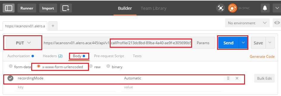
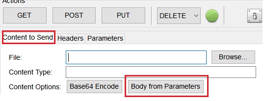
Note: If you use POSTER from firefox, you have to select Content to Send then select Body from Parameters before sending the PUT/POST, this way it's compiled in the code(s) that the CB can understand. As in the next image:
5. Add call Profile to the System Profiles
The callProfile defines whether calls can be recordings and if they can be done with or without user intervention.
Send a PUT with https://<Callbridge_IP>:445/api/v1/system/profiles after you add the callProfile in BODY
callProfile=<call profile ID>
For example:

If the recordingMode is set to Manual, you must set a DTMF profile to define how the users can start and stop recordings using DTMF tones.
6. Create the DTMF profile
a. Send a Post with https://<Callbridge_IP>:445/api/v1/dtmfProfiles after you’ve set the startRecording=**7 and stopRecording=**8 (for example) in BODY as startRecording=**7&stopRecording=**8.
For Example:
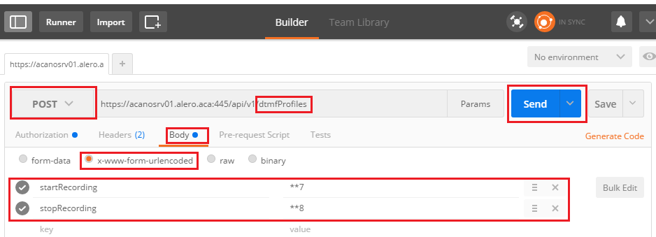
b. Send a GET to see the new DTMF profile, then copy the ID without the quotes to notepad.
7. Create CallLeg Profile
CallLegProfiles determines the in-call behavior. In this case it determines if a calls can be recorded.
Create a call leg profile as follows:
a. Send a Post with https://<Callbridge_IP>:445/api/v1/CallLegProfiles after you've added recordingControlAllowed=true in the BODY:
For example:

b. Apply the CallLegProfile, by sending a PUT with https://<Callbridge_IP>:445/api/v1/system/profiles and adding callLegProfile=<callLegProfile_ID> in the BODY:
For Example:

8. Apply the DTMF profile:
Send a PUT with https://<Callbridge_IP>:445/api/v1/system/profiles after you add the dtmfProfile in BODY dtmfProfile=<dfmt Profile ID>
For example:

Verify
Use this section in order to confirm that your configuration works properly
1. Once configured, check its status with these commands, you can get an output similar to that on the next image
recorder
Local standalone CB:
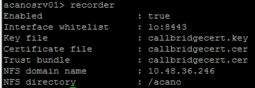
Or if clustered CB:

2. Send a GET to view the system profile, you must see the callProfile, CallLegProfile and dtmfProfile (assuming all these have been configured) in the result with
https://<Callbridge_IP>:445/api/v1/system/profiles
For example:

3. To check what's been configured on the CallProfile, use this on the API
https://<Callbridge_IP>:445/api/v1/callProfiles/<callProfile_ID>
This shows recording methods has been set, either Automatic or Manual, as shown:

4. To check what's configured on the CallLegProfile, use this API
https://<Callbridge_IP>:445/api/v1/callLegProfiles/<callLegProfile_ID>
Example output:

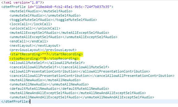
5. To check what's been configured on the DTMF Profile, use this on the API
https://<Callbridge_IP>:445/api/v1/dtmfProfiles/<dtmfProfile_ID>
This shows that recording methods has been set, either Automatic or Manual, as shown:
Note: DTMF profiles don’t work in point to point calls, so you can only use manual recording in a space.
Troubleshoot
This section provides information you can use in order to troubleshoot your configuration.
To display what's being logged with respect to the recorder, run the command:
syslog follow
The output displayed is similar to this:
Jun 20 20:38:49 kern.info acanosrv05 recorder-proxy[1]:  2016/06/20 20:38:49 Connection from 10.48.54.75:39439: Authentication succeeded
Jun 20 20:38:49 kern.info acanosrv05 recorder-proxy[1]:  2016/06/20 20:38:49 Connection from 10.48.54.75:39439: Connection terminated
Jun 20 20:38:53 kern.info acanosrv05 recorder-proxy[1]:  2016/06/20 20:38:53 Connection from 10.48.54.76:35141: Authentication succeeded
Jun 20 20:38:53 kern.info acanosrv05 recorder-proxy[1]:  2016/06/20 20:38:53 Connection from 10.48.54.76:35141: Connection terminated
In this example acanosrv05 is the server hosting the recorder and the other CB nodes connecting to it are 10.48.54.75 and 10.48.54.76.
This show that the remote CB are correctly connecting and authenticating with the Recorder.
If the recorder is local to the CB, then the connection would come from the loopback IP:
Jun 20 20:40:52 kern.info acanosrv01 recorder-proxy[1]:  2016/06/20 20:40:52 Connection from 127.0.0.1:45380: Authentication succeeded
Jun 20 20:40:52 kern.info acanosrv01 recorder-proxy[1]:  2016/06/20 20:40:52 Connection from 127.0.0.1:45380: Connection terminated
Note: Most logs related to the recorder processes are shown in the syslog as recorder-proxy, these give an indication where the recorder might be failing.
Other syslogs are shown as follows for the recorder:
In this case a recording device is found and the recording starts automatically:
Jun 20 21:16:19 user.info acanosrv02 host:server: INFO : recording device 1: available (1 recordings)
If the recording fails then check if a recording device is found:
Jun 20 21:16:19 user.info acanosrv02 host:server: INFO : No recording device found
If you see such warning, check the certificate in the recorder trust to ensure it's the correct one used to configure the CB.
Check the syslog to see whether the NFS storage is mounted:
- If the NFS storage is not mounted, "Failed to mount NFS storage" is displayed
- Check and ensure that the NFS folder set on the recorder server:/Folder-name is the same as what's configured on the NFS storage
Run the API to check alarms that relate to the recorder:
- https://<callBridge_IP>api/v1/system/alarms
- If there's low disk space "recorderLowDiskSpace" is displayed
- Then check that the NFS storage referenced by the recorder has enough diskspace
Related Information
Contributed by Cisco Engineers
- Joshua AleroCisco TAC Engineer
Contact Cisco
- Open a Support Case

- (Requires a Cisco Service Contract)
 Feedback