Integrate Multiple ISE Clusters with Secure Web Appliance for TrustSec Based Policies
Available Languages
Download Options
Bias-Free Language
The documentation set for this product strives to use bias-free language. For the purposes of this documentation set, bias-free is defined as language that does not imply discrimination based on age, disability, gender, racial identity, ethnic identity, sexual orientation, socioeconomic status, and intersectionality. Exceptions may be present in the documentation due to language that is hardcoded in the user interfaces of the product software, language used based on RFP documentation, or language that is used by a referenced third-party product. Learn more about how Cisco is using Inclusive Language.
Contents
Introduction
This document describes the procedure to send Security Group Tag (SGT) information from multiple ISE Deployments to a single Cisco Secure Web Appliance (Formally Web Security Appliance WSA) through pxGrid in order to take advantage of SGT-Based Web Access Policies in a TrustSec deployment.
Prior to version 14.5, Secure Web Appliance can only integrate with a single ISE cluster for identity policies based on SGT. With the introduction of this new version, Secure Web Appliance can now interoperate with information from multiple ISE clusters with a separate ISE node that aggregates between them. This brings great benefit and enables us to export user data from different ISE clusters and the liberty to control the exit point a user can use without the need for a 1:1 integration.
Prerequisites
Requirements
Cisco recommends that you have knowledge of these topics:
- Identity Services Engine (ISE)
- Secure Web Appliance
- RADIUS protocol
- TrustSec
- pxGrid
Components Used
The information in this document is based on these software and hardware versions:
- Secure Web Appliance 14.5
- ISE version 3.1 P3
The information in this document was created from the devices in a specific lab environment. All of the devices used in this document started with a cleared (default) configuration. If your network is live, ensure that you understand the potential impact of any command.
Limitations
- All ISE Cluster need to maintain uniform mappings for SGTs.
- ISE Aggregation Node must have the SGTs name/number of the rest of the ISE clusters.
- Secure Web Appliance can only identify policy (Access/Decryption/Routing) based on SGT Tag and not group nor username.
- Reporting and Tracking is SGT based.
- Existing ISE/Secure Web Appliance sizing parameters continue to apply for this feature.
Network Diagram
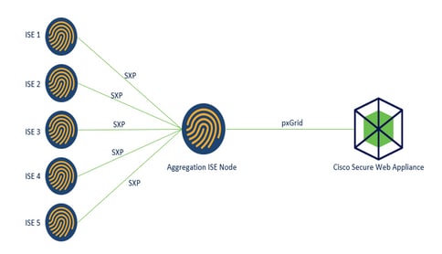
Process:
1. When the end user connects to the network, they receive an SGT based on Authorization policies in ISE.
2. The different ISE clusters then send this SGT information in form of SGT-IP mappings to ISE Aggregation Node through SXP.
3. ISE Aggregation Node receive this information and share with the single Secure Web Appliance through pxGrid.
4. Secure Web Appliance uses the SGT information it has learnt to provide access to users based on Web Access Policies.
Configure
ISE Configuration
Enable SXP
Step 1. Select the three lines icon  located in the upper left corner and select on Administration > System > Deployment.
Step 2. Select the node you want to configure and click Edit.

Step 3. To enable SXP, tick the box Enable SXP Service
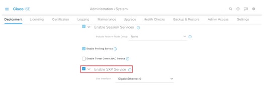
Step 4. Scroll down to the bottom and click Save
Note: Repeat all the steps for the rest of the ISE nodes in each cluster, the aggregation node included.
Configure SXP on the cluster nodes
Step 1. Select the three lines icon located in the upper left corner and select on Work Center > TrustSec > SXP.
Step 2. Click +Add to configure the ISE aggregation node as an SXP peer.

Step 3. Define the Name and IP address of the ISE aggregation node, select peer role as LISTENER. Select required PSNs under Connected PSNs, required SXP Domains, select Enabled under status, then select Password Type and required Version.
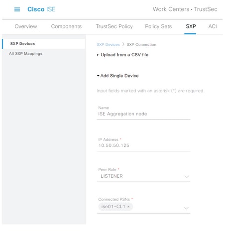
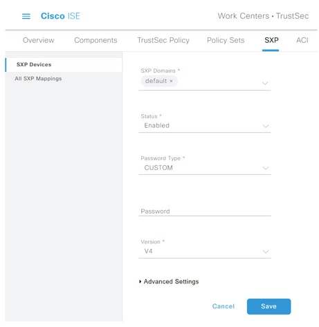
Step 4. Click Save
Note: Repeat all the steps for the rest of the ISE nodes in each cluster to build an SXP connection to the aggregation node. Repeat the same process on the aggregation node and select SPEAKER as peer role.
Configure SXP on the aggregation node
Step 1. Select the three lines icon located in the upper left corner and select on Work Center > TrustSec > Settings
Step 2. Click the tab SXP Settings
Step 3. To propagate the IP-SGT mappings, tick the Publish SXP bindings on pxGrid check box.
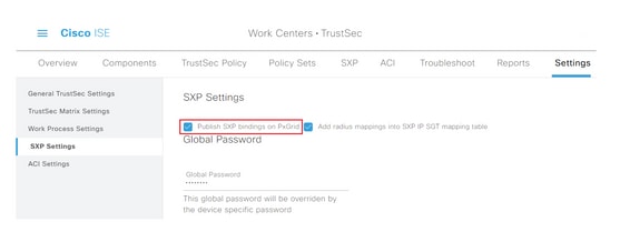
Step 4 (Optional). Define a default password for SXP settings under Global Password
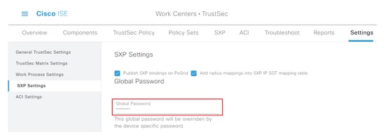
Step 5. Scroll down and click Save.
Enable pxGrid on the aggregation node
Step 1. Select the three lines icon located in the upper left corner and select on Administration > System > Deployment.
Step 2. Select the node you want to configure and click Edit.

Step 3. To enable pxGrid, click the button next to pxGrid.
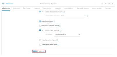
Step 4. Scroll down to the bottom and click Save.
pxGrid Auto Approval
Step 1. Navigate to three lines icon located in the upper left corner and select Administration > pxGrid Services > Settings.
Step 2. By default, ISE does not automatically approve pxGrid the connection requests from new pxGrid clients, therefore you must enable that setting by select the checkbox Automatically approve new certificate-based accounts.
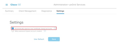
Step 3. Click Save
Network devices TrustSec settings
For Cisco ISE to process requests from TrustSec-enabled devices, you must define these TrustSec-enabled devices in Cisco ISE.
Step 1. Navigate to the three lines iconlocated in the upper left corner and select on Administration > Network Resources > Network Devices.
Step 2. Click +Add.

Step 3. Enter the required information in the Network Devices section and in RADIUS Authentication Settings.
Step 4. Check the Advanced TrustSec Settings check box to configure a TrustSec-enabled device.

Step 5. Click the Use Device ID for TrustSec Identification check box to automatically populate the Device Name listed in the Network Devices section. Enter a password in the Password field.
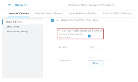
Note: The ID and password must match the “cts credentials id <ID> password <PW>” command that is later configured on the switch.
Step 6. Check the Send configuration changes to device check box so that ISE can send TrustSec CoA notifications to the device.
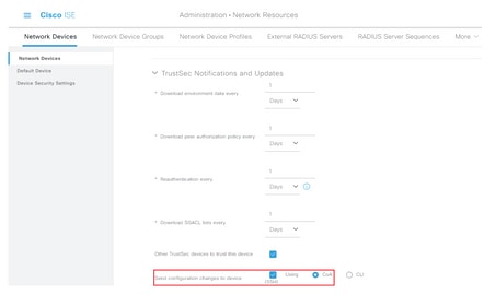
Step 7. Check the Include this device when deploying Security Group Tag Mapping Updates check box.
Step 8. In order to let ISE edit the configuration of the network device, enter the user credentials in the EXEC Mode Username and EXEC Mode Password fields. Optionally, provide enable password in the Enable Mode Password field.
Note: Repeat the steps for all other NADs that are intended to be a part of the TrustSec domain.
Network Device Authorization
Step 1. Select the three lines icon located in the upper left corner and select on Work Centers > TrustSec > TrustSec Policy.
Step 2. In the left pane, click Network Device Authorization.

Step 3. On the right, use the drop-down next to Edit and Insert new row above to create a new NDA rule.

Step 4. Define a Rule Name, Conditions and select the appropriate SGT from the drop-down list under Security Groups.
Step 5. Click Done to the far right.

Step 6. Scroll down and click Save.
SGT
Step 1. Select the three lines icon located in the upper left corner and select on Work Centers > TrustSec > Components.
Step 2. In the left pane, expand Security Groups.
Step 3. Click +Add to create a new SGT.

Step 4. Enter the name and choose an icon in the appropriate fields.
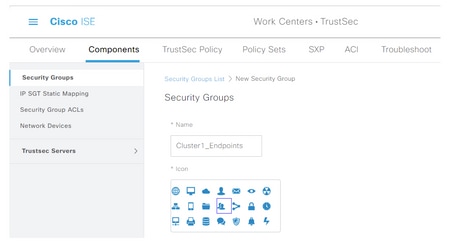
Step 5. Optionally, give it a description and enter a Tag Value.
Note: In order to be able to manually enter a Tag Value, navigate to Work Centers > TrustSec > Settings > General TrustSec Settings and select the option User Must Enter SGT Number Manually under Security Group Tag Numbering.
Step 6. Scroll down and click Submit
Note: Repeat these steps for all required SGTs.
Authorization Policy
Step 1. Select the three lines icon located in the upper left corner and select on Policy > Policy Sets.
Step 2. Select the appropriate policy set.
Step 3. Within the policy set, expand the Authorization Policy.
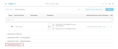
Step 4. Click the  button to create an Authorization Policy.

Step 5. Define the required Rule Name, Condition/s, and Profiles and select the appropriate SGT from the drop-down list under Security Groups.

Step 6. Click Save.
Enabling ERS on ISE Aggregation Node (Optional)
The External RESTful API Service (ERS) is an API that can be queried by the WSA for group information. The ERS service is disabled by default on ISE. Once it is enabled, clients can query the API if they authenticate as members of the ERS Admin group on the ISE node. To enable the service on ISE and add an account to the correct group, follow these steps:
Step 1. Select the three lines icon located in the upper left corner and select on Administration > System > Settings.
Step 2. In the left pane, click ERS Settings.
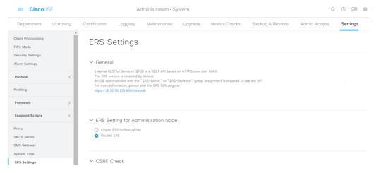
Step 3. Select the option Enable ERS for Read/Write.
Step 4. Click Save and confirm with OK.
Add user to ESR Admin group (Optional)
Step 1. Select the three lines icon located in the upper left corner and select Administration > System > Admin Access
Step 2. In the left pane, expand Administrators and click Admin Users.
Step 3. Click +Add and select Admin User from the drop-down.

Step 4. Enter a username and password in the appropriate fields.
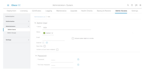
Step 5. In the Admin Groups field, use the drop-down to select ERS Admin.
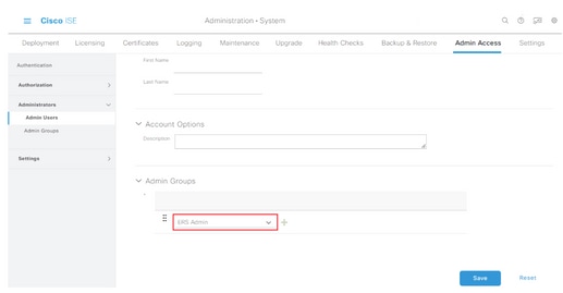
Step 6. Click Save.
Secure Web Appliance Configuration
Root certificate
If the integration design uses an internal certificate authority as the root of trust for the connection between the WSA and ISE, then this root certificate must be installed on both appliances.
Step 1. Navigate to Network > Certificate Management and click on Manage Trusted Root Certificates to add a CA certificate.
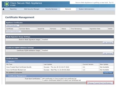
Step 2. Click on Import.

Step 3. Click on Choose File to locate the generated Root CA and click Submit.
Step 4. Click Submit again.
Step 5. At the upper right corner, click Commit Changes.

Step 6. Click Commit Changes again.
pxGrid Certificate
In the WSA, the creation of the key pair and certificate for use by pxGrid is completed as part of the ISE services configuration.
Step 1. Navigate to Network > Identity Service Engine.
Step 2. Click on Enable and Edit Settings.
Step 3. Click on Choose File to locate the generated Root CA and click Upload File.

Note: A common misconfiguration is to upload the ISE pxGrid certificate in this section. The root CA certificate must be uploaded to the ISE pxGrid Node Certificate field.
Step 4. In the Web Appliance Client Certificate section, select Use Generated Certificate and Key.

Step 5. Click the Generate New Certificate and Key button and complete the required certificate fields.
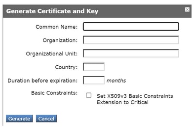
Step 6. Click on Download Certificate Signing Request.
Note: It is recommend to select the Submit button to commit the changes to the ISE configuration. If the session is left to timeout before the changes are submitted, the keys and certificate that were generated can be lost, even if the CSR was downloaded.
Step 7. After you have signed the CSR with your CA, click on Choose File to locate the certificate.
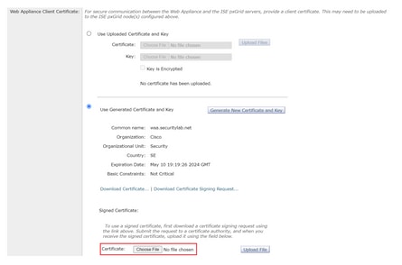
Step 8. Click Upload File.
Step 9. Submit and Commit.
Enable SXP and ERS on Secure Web Appliance
Step 1. Click the Enable buttons for both SXP and ERS.

Step 2. In the ERS Administrator Credentials field, enter the user information that was configured on ISE.
Step 3. Check the box for Server name same as ISE pxGrid Node to inherit the earlier configured information. Otherwise, enter the required information there.

Step 4. Submit and Commit.
Identification Profile
In order to use security group tags or ISE group information in the WSA policies, an identification profile must first be created that utilizes ISE as a means to transparently identify users.
Step 1. Navigate to Web Security Manager > Authentication > Identification Profiles.
Step 2. Click on Add Identification Profile.
Step 3. Enter a name and optionally a description.
Step 4. In the Identification and Authentication section, use the drop-down to choose Transparently identify users with ISE.
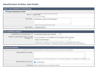
Step 5. Submit and Commit.
SGT Based Decryption Policy
Step 1. Navigate to Web Security Manager > Web Policies > Decryption Policies.
Step 2. Click Add Policy.
Step 3. Enter a name and optionally a description.
Step 4. In the Identification Profiles and Users section, use the drop-down to choose Select One or More Identification Profiles.
Step 5. In the Identification Profiles section, use the drop-down to choose the name of the ISE identification profile.
Step 6. In the Authorized Users and Groups section, select Selected Groups and Users.
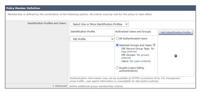
Step 7. Click the hyperlink next to ISE Secure Group Tags.
Step 8. In the Secure Group Tag Search section, check the box to the right of the desired SGT and click Add.
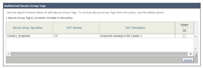
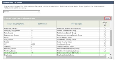
Step 9. Click Done to return.
Step 10. Submit and Commit.
Switch Configuration
AAA
aaa new-model

aaa group server radius ISE
 server name ise01-cl1
 server name ise02-cl1
 ip radius source-interface Vlan50

aaa authentication dot1x default group ISE
aaa authorization network ISE group ISE
aaa accounting update newinfo periodic 2440
aaa accounting dot1x default start-stop group ISE

aaa server radius dynamic-author
 client 10.50.50.120 server-key Cisco123
 client 10.50.50.121 server-key Cisco123
 auth-type any

radius server ise01-cl1
 address ipv4 10.50.50.121 auth-port 1812 acct-port 1813
 pac key Cisco123
radius server ise02-cl1
 address ipv4 10.50.50.120 auth-port 1812 acct-port 1813
pac key Cisco123
TrustSec
cts credentials id SW1 password Cisco123 (This is configured in Privileged EXEC Mode)
cts role-based enforcement

aaa authorization network cts-list group ISE
cts authorization list cts-list
Verify
SGT assignment from ISE to endpoint.
Here you can see an endpoint from ISE Cluster 1 assigned an SGT after successful authentication and authorization:

Here you can see an endpoint from ISE Cluster 2 assigned an SGT after successful authentication and authorization:

SXP Mappings
Since SXP communication is enabled between the cluster ISE nodes and ISE aggregation node, these SGT-IP mappings are learned by ISE aggregation through SXP:
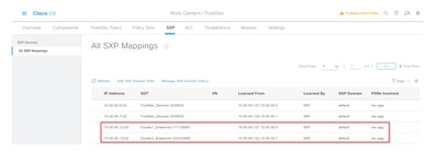
These SXP mappings, from different ISE clusters, are then sent to WSA over pxGrid through the ISE aggregation node:

SGT based policy enforcment
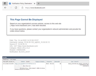
Here you can see the different endpoints match its respective policies and traffic are blocked based on their SGT:
Endpoint that belongs to ISE Cluster 1
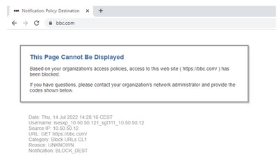

Endpoint that belongs to ISE Cluster 2
Related Information
Revision History
| Revision | Publish Date | Comments |
|---|---|---|
1.0 |
22-Jul-2022 |
Initial Release |
Contributed by
- Emmanuel CanoCisco Security Consulting Engineer
- Deniz YildirimCisco Security Consulting Engineer
- Berenice GuerraCisco Technical Consulting Engineer
Contact Cisco
- Open a Support Case

- (Requires a Cisco Service Contract)
 Feedback