Attaching a US Robotics Modem to the Console Port of a Cisco Router
Available Languages
Contents
Introduction
This document explains how to attach a US Robotics modem to the Console port of Cisco routers that have RJ-45 console ports. This procedure can be used for other modem brands as well, however you must consult your modem documentation for the equivalent initialization string.
 Warning: Unprotected modems should not be connected to the console port. The console ports do not log users off when the carrier detect is lost, which can leave a security hole. To avoid this, use a secure modem, or connect via the AUX port. For more information on the advantages and disadvantages of connecting a modem to the Console port, refer to the Modem-Router Connection Guide.
Note: This document does not cover the procedure to configure a modem to the AUX port of a router. For more information on connecting a modem to the AUX port refer to Configuring a Modem on the AUX Port for EXEC Dialin Connectivity.
Prerequisites
Requirements
There are no specific requirements for this document.
Components Used
This document is not restricted to specific software and hardware versions.
The information presented in this document was created from devices in a specific lab environment. All of the devices used in this document started with a cleared (default) configuration. If you are working in a live network, ensure that you understand the potential impact of any command before using it.
Conventions
Refer to Cisco Technical Tips Conventions for more information on document conventions.
Tasks Performed
-
Configure the modem for console connectivity. Since the the console port lacks reverse telnet capability, the modem initialization string (init string) must be set prior to connecting the modem to the console port of the router.
-
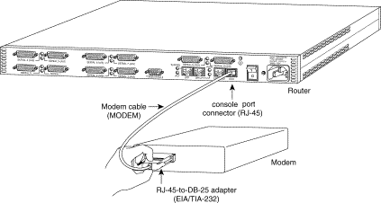
Connect the modem to the console port of the router.
-
Configure the router to accept incoming calls.
These tasks are explained in the Step-by-Step section shown below.
Step-By-Step
Follow the steps below to attach a US Robotics modem to the console port of a Cisco router:
-
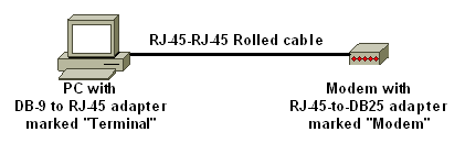
Connect the modem to a PC. This step is necessary to access the modem to set the init string.
Attach an RJ-45-to-DB-9 adapter marked "Terminal" to the COM port of the PC. From the RJ-45 end of the adapter, connect a flat-satin Rolled RJ-45--RJ-45 cable (part number CAB-500RJ= ), which is provided with every Cisco router for console connections. You also need a RJ-45 to DB-25 adapter marked "MODEM" (part number CAB-25AS-MMOD) to connect the rolled cable to the DB-25 port on the modem.

-
On the modem, restore the factory defaults by turning off the modem, setting DIP switch seven down and turning on the modem. After this, turn the modem off again. Reference the Miscellaneous section of this document for information about DIP switch settings
-
Set DIP switches one, three and eight down and all others up. Turn the modem back on. Reference the Miscellaneous section of this document for information about DIP switch settings
-
Reverse Telnet from the PC to the Modem
Use a terminal emulation program on the PC, such as Hyperterminal, and access the PCs modem through the COM port you connected to in step 1. Once you have connected to the PC's modem through the COM port, you will need to apply the initialization string as described below. For an example, refer to the Example HyperTerminal Session of the Configuring Client Modems to Work with Cisco Access Servers document.
-
Type the following initialization string which will write the desired init string settings to NVRAM:
at&f0qle0s0=1&b0&n6&u6&m4&k0&w
Note: The 0s in the string above are zeroes. Reference the Miscellaneous section of this document for information about init strings.
Note: You should receive an OK response from the modem. If the modem does not respond, verify that the modem hardware and cabling are functioning correctly.
-
Turn off the modem.
-
Unplug the rolled RJ-45 cable from the PCs RJ-45-to-DB-9 adapter and attach it to the Console port of the router

For routers with a DB-25 CONSOLE port (for example, Cisco 4500, 7200 and 7500) you need a DB-25-to-DB-25 Null Modem cable. This cable can be purchased from most retail electronic outlet stores.
Note: A rolled RJ-45-to-RJ-45 flat satin cable with RJ-45-to-DB-25 adapters (part number CAB-25AS-MMOD) on both ends CANNOT be used due to incorrect signal pairs.
-
Set DIP switches one, four, six and eight down and all others up. Reference the Miscellaneous section of this document for information about DIP switch settings
-
Turn the modem on.
-
Configure the router
maui-rtr-10(config)#line con 0
maui-rtr-10(config-line)#login

!-- Authenticate incoming connections using the password configured on the line. !-- This password is configured below:

maui-rtr-10(config-line)#password cisco

!-- The router will use this password (cisco) to authenticate incoming calls. !-- For security purposes, replace "cisco" with a password that is not well known.

maui-rtr-10(config-line)#exec-time 5 0

!-- Set the exec timeout to be 5 minutes and 0 seconds !-- This exec timeout clears the EXEC session after 5 minutes of inactivity !-- For information refer to the Modem-Router Connection Guide

maui-rtr-10(config-line)#speed 9600

!--- console line speed that should be used to communicate with the modem !--- This speed matches the DTE speed configured in the init string (&u6) !--- Refer to the section Miscellaneous for more information
Optional Configuration: If the router does not have an enable secret password, incoming connections will not be able to enter the enable mode. To allow incoming calls to enter enable mode, use the command enable secret password to setup the enable password.
-
Use an analog phone to verify that the phone line is active and functioning. Then, connect the analog phone line to the modem.
-
Test the modem connection by initiating an EXEC modem call to the router from another device (for example, a PC).
Use a terminal emulation program on the PC, such as Hyperterminal, and access the PCs modem through one of the COM ports. Once you have connected to the PC's modem through the COM port, initiate the dial to the router. For an example, refer to Example HyperTerminal Session.
Note: The Console port line is not running Point-to-Point Protocol (PPP), hence you cannot dial using Microsoft Windows Dialup Networking (DUN) for this connection.
-
Once the connection is established, press <Return> to obtain the router prompt . The dialin client will then be prompted for a password. Enter the correct password.
Note: This password must match the one configured on the CON port line.
Miscellaneous
Dip Switches
The following table contains a listing of the functions of the DIP switches on a US Robotics Modem:
ON = Down, OFF = Up.
| Dip Switch | Description |
|---|---|
| 1 | DTR Override |
| 2 | Verbal/Numeric Result Codes |
| 3 | Result Code Display |
| 4 | Command Mode Local Echo Suppression |
| 5 | Auto Answer Suppression |
| 6 | CD Override |
| 7 | Power-on and ATZ Reset Software Defaults |
| 8 | AT Command Set Recognition |
Initialization String
The init string entered for this configuration had the following characteristics:
at&f0qle0s0=1&b0&n6&u6&m4&k0&w
| AT command | Description |
|---|---|
| &f0 | Set to Factory Defaults (no Flow Control) |
| q1 | Eliminates result codes |
| e0 | Disable echoing commands |
| s0=1 | Auto Answer on first ring |
| &b0 | Floating DTE Speed |
| &n6 | Highest Link Speed (DCE rate) is 9600bps |
| &u6 | DTE speed maximum is 9600 (DTE follows DCE speed) |
| &m4 | ARQ/Normal Mode |
| &k0 | Disable Data Compression |
| &w | Store configuration to nvram |
Related Information
Revision History
| Revision | Publish Date | Comments |
|---|---|---|
1.0 |
04-Feb-2010 |
Initial Release |
Contact Cisco
- Open a Support Case

- (Requires a Cisco Service Contract)


 Feedback