Field Notice: FN - 63132 - MDS9000 - Potential DIMM Memory issue in small number of DS-X9530-SF2-K9 supervisor cards manufactured between September 2007 and February 2008. - Replace on Failure
Available Languages
Notice
THIS FIELD NOTICE IS PROVIDED ON AN "AS IS" BASIS AND DOES NOT IMPLY ANY KIND OF GUARANTEE OR WARRANTY, INCLUDING THE WARRANTY OF MERCHANTABILITY. YOUR USE OF THE INFORMATION ON THE FIELD NOTICE OR MATERIALS LINKED FROM THE FIELD NOTICE IS AT YOUR OWN RISK. CISCO RESERVES THE RIGHT TO CHANGE OR UPDATE THIS FIELD NOTICE AT ANY TIME.
Revision History
| Revision | Publish Date | Comments |
|---|---|---|
1.0 |
14-Jul-10 |
Initial Release |
10.0 |
29-Nov-17 |
Migration to new field notice system |
10.1 |
18-Jan-19 |
Fixed Broken Image Links |
10.2 |
22-Jan-19 |
Updated the Product Hierachy Metatags |
Products Affected
| Affected Product ID | Comments |
|---|---|
DS-X9530-SF2-K9 |
|
DS-X9530-SF2AK9= |
Part Alternate |
Defect Information
| Defect ID | Headline |
|---|---|
| CSCvf34445 | There were no defects filed with this field notice at the time of publication. |
Problem Description
Cisco has been made aware of a limited number of Supervisor-2 modules (DS-X9530-SF2-K9), manufactured between September 2007 to February 2008, that may intermittently experience a Device-4 error caused by an ECC Memory error (Error Correcting Code). This error will cause the Supervisor module to randomly switchover.
Some Supervisor-2 modules (DS-X9530-SF2-K9) with Serial Numbers within the range JAE1136xxxx to JAE1209xxxx may be affected.
Background
Cisco has determined the root cause to be infrequent DIMM errors caused by the printed circuit board design of a particular DIMM vendor. The printed circuit board design from this particular DIMM vendor may introduce a marginal memory timing condition whereby an infrequent read timing violation would occur under certain DIMM activity conditions. This violation would result in an ECC memory error (a Device 4 Error). Based upon this determination, the risk profile to customers who have Supervisor 2 modules with affected DIMMs, and in the interest of preventing further failures, Cisco is recommending that affected DIMMs are replaced.
Cisco builds with multiple DIMM vendors; only one of these secondary vendors has this condition accounting for a small percentage of affected Supervisor 2 modules manufactured between September 2007 to February 2008.
Problem Symptom
On Supervisor 2 modules with the affected DIMM, the Supervisor may randomly fail due to a Device 4 Error.
If the following message is displayed when you issue the show system reset-reason CLI command, the Supervisor 2 module will need the DIMM to be replaced by contacting the Cisco TAC and requesting a replacement DIMM per this Field Notice.
switch# show system reset-reason

----- reset reason for Supervisor-module 5 (from supervisor in slot 5)---

1) No time

Reason: Unknown

Service:

Version: 3.2(2c)

2) At 69022 usecs after Fri Jun 6 12:57:39 2008

Reason: Supervisor Device Error

Service: SUP Device-4 err

Version: 3.2(2c)
Workaround/Solution
Cisco recommends the replacement of all affected DIMMs in the field. To do this, Cisco will provide the m9500-sup2dimm-gplug-mz.3.4.1.bin utility to electronically verify the affected DIMM on Supervisor 2 modules.
To replace the DIMMs, do the following:
A. Identify affected DIMM
B. Request replacement for affected DIMM
C. Replace the original DIMM
Follow the detailed steps in the following sections to complete these procedures.
A - Identify Affected DIMM
Affected DIMMs can be identified by the following methods:
- Identifying Affected DIMMs Using Fabric Manager Release 3.4(1z)
- Running the m9500-sup2dimm-gplug-mz.3.4.1.bin Utility
- Inspecting the DIMMs
Identifying Affected DIMMs Using Fabric Manager Release 3.4(1z)
Fabric Manager Release 3.4(1z) is a special release distributed only to identify affected DIMMs in Supervisor 2 modules across your fabric. The utility discovers affected DIMMs in all Supervisor 2 modules in your fabric and generates a report indicating all affected DIMMs.
Note - Users installing Fabric Manager must have full administrator privileges to create user accounts and start services. Users should also have access to all ports. These are the ports used by Fabric Manager Server and the PostgreSQL database: 1098, 1099, 4444, 4445, 8009, 8083, 8090, 8092, 8093, 514, 5432.
Fabric Manager Release 3.4(1z) is included in the m9500-sup2dimm-gplug-mz.3.4.1.bin.zip file. To obtain Release 3.4(1z), go to the following URL: http://www.cisco.com/cgi-bin/tablebuild.pl/mds-utilities
A CCO account is required to download the file. Click on m9500-sup2dimm-gplug-mz.3.4.1.bin.zip to download the zip file to your computer and unzip the file. The DIMM Utility folder is created. The folder contains 3 items: the MDS9000-FM-CD-3.4.1z folder, the m9500-sup2dimm-gplug-mz.3.4.1.bin standalone utility, and the DIMMutility.pdf.
Installation Pre-Requisites
Browser Requirement
Installation requires Windows Internet Explorer 6.x and 7.0. Internet Explorer 7.0 is not supported on Windows 2000 SP4.
Java Requirement
When you connect to the server for the first time, Fabric Manager checks to see if you have the correct Sun Java Virtual Machine version installed on your workstation. Fabric Manager looks for version 1.5(x) during installation. If required, install the Sun Java Virtual Machine software.
Note - You can run CiscoWorks on the same PC as Fabric Manager, even though the Java requirements are different. When installing the later Java version for Fabric Manager, make sure it does not overwrite the earlier Java version required for CiscoWorks. Both versions of Java can coexist on your PC.
PostgreSQL Requirement
On Windows, remote Fabric Manager Installations or upgrades should be done through the console using VNC or through the Remote Desktop Client (RDC) in console mode (ensuring RDC is used with the /Console option). This is vitally important if the default PostgreSQL is used with Fabric Manager, as this database requires the local console for all installations and upgrades.
Installing Fabric Manger Release 3.4(1z)
You can create an installation CD or you can run the installation from the MDS9000-FM-CD-3.4.1z folder.
To run the installation on Windows from the MDS9000-FM-CD-3.4.1z folder, do the following:
Step 1 - Double-click install_windows.htm.
Step 2 - Click the Install Management Software link.
Step 3 - Choose Management Software > Cisco Fabric Manager in the left navigation pane. You may need to allow blocked content in order to install Fabric Manager.
Step 4 - Click the Installing Fabric Manager link.
Step 5 - Click the FM Installer link. Click OK. It may take a couple of minutes for the Fabric Manager installation window to open.
You see the welcome to the management software setup wizard message in the Cisco Fabric Manager Installer window shown in Figure 1-1.
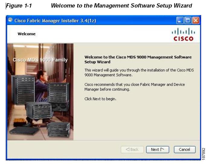
Step 6 - Click Next to begin the installation.
Step 7 - Check the I accept the terms of the License Agreement check box and click Next.
You see the Install Options dialog box shown in Figure 1-2.
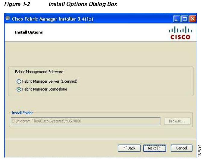
Step 8 - Click the radio button for either:
a. Fabric Manager Server (Licensed) to install the server components for Fabric Manager Server.
b. Fabric Manager Standalone to install the standalone version of Fabric Manager. (Recommended installation)
Note - You should verify that the Fabric Manager Server hostname entry exists on the DNS server, unless the Fabric Manager Server is configured to bind to a specific interface during installation.
Note - Fabric Manager Standalone is a single application containing Fabric Manager Client and a local version of Fabric Manager Server bundled together. Fabric Manager Standalone allows you to discover and monitor the immediate fabric.
Step 9 - (For Fabric Manager server installation) Select an installation folder on your workstation for Fabric Manager. On Windows, the default location is C:\Program Files\Cisco Systems\MDS 9000. On a UNIX (Solaris or Linux) machine, the installation path name is /usr/local/cisco_mds9000 or $HOME/cisco_mds9000, depending on the permissions of the user doing the installation.
Step 10 - Click Next. You see the Database Options dialog box shown in Figure 1-3.
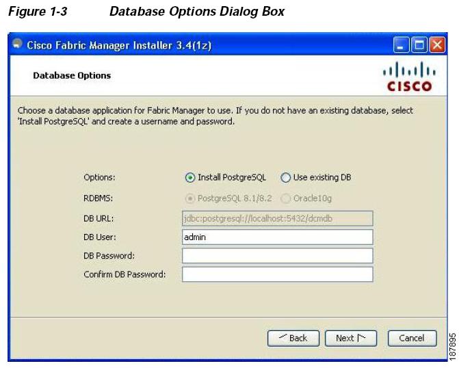
Step 11 - Click the radio button for either Install PostgreSQL or Use existing DB to specify which database you want to use.
If you choose Install PostgreSQL, accept the defaults and enter a password. The PostgreSQL database will be installed.
Note - If you choose to install PostgreSQL, you must disable any security software you are running, as PostgreSQL may not install certain folders or users. Note - Before you install PostgreSQL, remove the cygwin/bin from your environment variable path if Cygwin is running on your system.
Step 12 - If you select Use existing DB, click the radio button for either PostgreSQL 8.1/8.2 or Oracle10g.
Step 13 - Click Next in the Database Options dialog box.
You see the User Options dialog box shown in Figure 1-4.
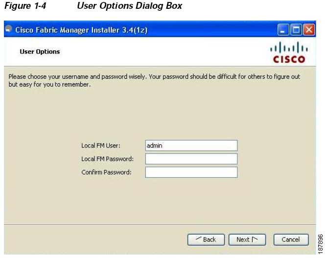
Step 14 - Enter a user name and password and click Next.
You see the Authentication Options dialog box shown in Figure 1-5.
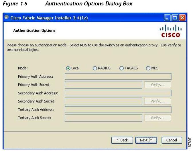
Step 15 - Choose an authentication mode (Local, RADIUS, TACACS or MDS) and click Next.
Note - When the MDS radio button is selected, the FM authentication uses the user database in the switch for authentication.
Step 16 - Click Verify to test your login if you choose RADIUS or TACACS.
You see the Configuration Options dialog box for Fabric Manager Standalone shown in Figure 1-6.
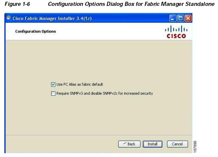
Step 17 - Check the FC Alias and SNMPv3 check boxes as desired and click Install if you are installing Fabric Manager Standalone.
You see the Configuration Options dialog box for Fabric Manager Server shown in Figure 1-7.
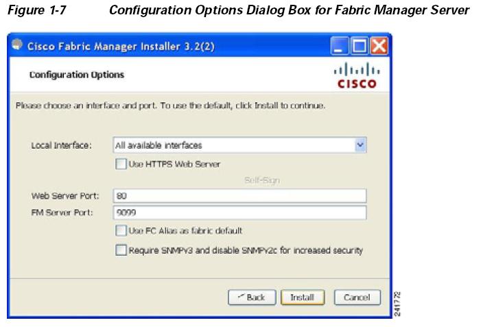
Step 18 - Select the local interface, web server port or fm server port and check the FC Alias and SNMPv3 check boxes as desired and click Install if you are installing Fabric Manager Server.
Note - You can change the FM Server Port number, to a port that is not used by any other application.
Note - You should verify that the Fabric Manager Server hostname entry exists on the DNS server, unless the Fabric Manager Server is configured to bind to a specific interface during installation.
Note - If you check the Use HTTPS Web Server check box, the Web Server Port field is grayed out and the default port is 443.
Note - If you select a specific IP address during installation and change the server host IP address, you must modify the following two files which are all located in the $INSTALL/conf directory. Change server.bindaddrs to the new IP address in the server.properties file and change wrapper.app.parameter.4 to the new IP address in the FMServer.conf file.
Step 19 - You see the installation progress in the Cisco Fabric Manager Installer window.
Once the installation is finished, you see an installation completed message in the Cisco Fabric Manager Installer window shown in Figure 1-8.
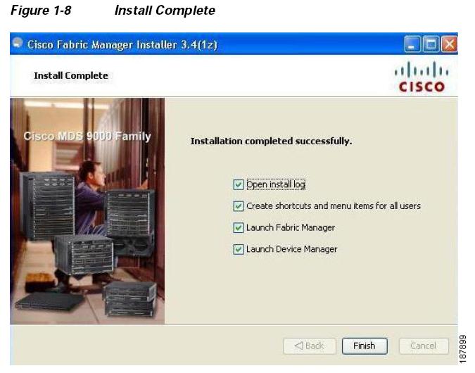
Note - If you installed Fabric Manager Standalone, you can choose to launch Fabric Manager or Device Manager by checking the Launch Fabric Manager or Launch Device Manager check boxes.
Step 20 - Create a desktop shortcut & Launch Fabric Manager now.
Step 21 - Enter the Fabric Manager Server Username and Fabric Manager server password that you assigned. Click Login
Step 22 - Enter the seed switch IP address, username, and password. Insure that SNMPv3 is checked and select the appropriate Auth-Privacy authentication shown in Figure 1-9.
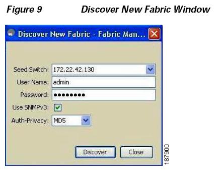
Step 23 - Click Discover. A verification of the discovered fabric is displayed. Click OK. The Control Panel window is displayed shown in Figure 1-10.

Step 24 - Select the device and click Open. The Fabric Manager window displays the fabric.
Step 25 - Select Tools > DIMM Report.... to run the DIMM utility report shown in Figure 1-11.
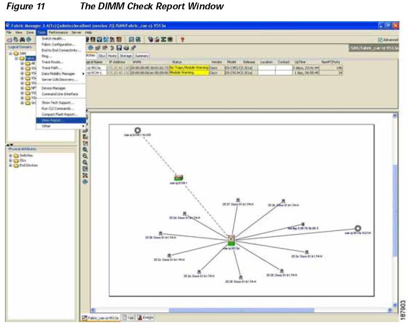
The DIMM Check Report window is displayed shown in Figure 1-12.
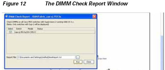
Step 26 - Select the Cisco MDS switches in your fabric.
Step 27 - Enter the directory where the report will be saved. Click Run shown in Figure 1-13.
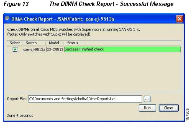
Step 28 - Click Close shown in Figure 1-14.
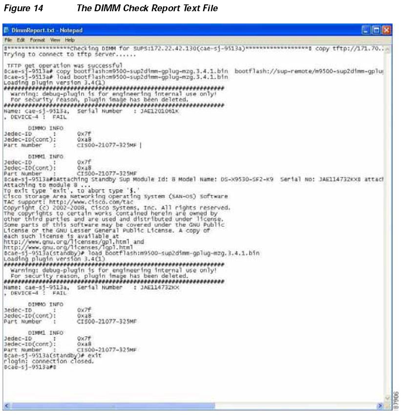
Running the m9500-sup2dimm-gplug-mz.3.4.1.bin Utility
The m9500-sup2dimm-gplug-mz.3.4.1.bin utility will run on SAN-OS Release 3.x running on Supervisor 2 modules. Pictures of the affected DIMM are in the "How to Visually Inspect DIMMs" section of this Field Notice. The visual inspection method is recommended for Supervisors that are offline.
To download and run the m9500-sup2dimm-gplug-mz.3.4.1.bin utility using the CLI, do the following:
Step 1 - Go to the following URL MDS Utilities (http://www.cisco.com/cgi-bin/tablebuild.pl/mds-utilities) Click m9500-sup2dimm-gplug-mz.3.4.1.bin.zip to download the utility to your computer.
Step 2 - Unzip the file and save to your local computer.
Step 3 - Copy the utility to a tftp server.
Step 4 - Copy the utility from the tftp server to the Cisco MDS 9000 Family switch.
An example of the CLI command used to copy the utility from the tftp server to the active Supervisor 2 module is:
switch#copy tftp://192.68.55.22/m9500-sup2dimm-gplug-mz.3.4.1.bin

bootflash:m9500-sup2dimm-gplug-mz.3.4.1.bin

Trying to connect to tftp server......|

TFTP get operation was successful

switch#
Step 5 - Copy the m9500-sup2dimm-gplug-mz.3.4.1.bin utility to the standby Supervisor 2 module.
switch#copy bootflash:m9500-sup2dimm-gplug-mz.3.4.1.bin
bootflash://sup-standby/m9500-sup2dimm-gplug-mz.3.4.1.bin
Step 6 - Run the utility on the active Supervisor 2 module by issuing the following commands. The utility will be removed from the active Supervisor 2 module during the process of running the load command.
Be sure to type the command correctly. You can not use the Tab key to auto-expand the command.
switch#load bootflash:m9500-sup2dimm-gplug-mz.3.4.1.bin

Loading plugin version 3.4(1)

###############################################################

Warning: debug-plugin is for engineering internal use only!

For security reason, plugin image has been deleted.

###############################################################

Name: switch, Serial Number : JAE11528POD

, DEVICE-4 : FAIL

DIMMO INFO

Jedec-ID : 0x7f

Jedec-ID(cont): 0xa8

Part Number : CIS00-21077-325MF

DIMM1 INFO

Jedec-ID : 0x7f

Jedec-ID(cont): 0xa8

Part Number : CIS00-21077-325MF
The utility output will indicate a "PASS" or "FAIL" status for the DIMM on the Supervisor 2 module. If you see a FAIL status, follow the procedure to order the DIMM replacement using the form at the end of this document.
Step 7 - Run the utility on the standby Supervisor by issuing the following commands. Use the "show module" command first to identify the standby Supervisor module
switch# show module

Mod Ports Module-Type Model Status

--- ----- -------------------------------- ------------------------------

1 32 1/2 Gbps FC Module DS-X9032 ok

2 16 1/2 Gbps FC Module DS-X9016 ok

4 8 IP Storage Services Module DS-X9308-SMIP ok

5 0 Supervisor/Fabric-2 DS-X9530-SF2-K9 active *

6 0 Supervisor/Fabric-2 DS-X9530-SF2-K9 ha-standby

9 8 IP Storage Services Module DS-X9308-SMIP ok

Mod Sw Hw World-Wide-Name(s) (WWN)

--- -------------- ------ --------------------------------------------------

1 3.2(2c) 1.0 20:01:00:05:30:00:63:9e to 20:20:00:05:30:00:63:9e

2 3.2(2c) 1.0 20:41:00:05:30:00:63:9e to 20:50:00:05:30:00:63:9e

4 3.2(2c) 2.0 --

5 3.2(2c) 1.6 --

6 3.2(2c) 1.4 --

9 3.2(2c) 5.1 --

Mod MAC-Address(es) Serial-Num

--- -------------------------------------- ----------

1 00-0c-30-0c-91-d0 to 00-0c-30-0c-91-d4 JAB0652050V

2 00-0c-30-0c-96-30 to 00-0c-30-0c-96-34 JAB0716054W

4 00-0c-30-da-24-74 to 00-0c-30-da-24-80 JAB075005QN

5 00-1a-e2-03-92-98 to 00-1a-e2-03-92-9c JAE11528POD

6 00-1a-e2-03-85-3c to 00-1a-e2-03-85-40 JAE120782Z8

9 00-0d-ec-0e-d5-12 to 00-0d-ec-0e-d5-1e JAB09080069
Step 8 - Attach to the standby Supervisor module.
switch#attach module 6 http://www.cisco.com/tac  Copyright (c) 2002-2007, Cisco Systems, Inc. All rights reserved.

The copyrights to certain works contained herein are owned by other third parties and are used and distributed under license.

Some parts of this software may be covered under the GNU Public License or the GNU Lesser General Public License. A copy of each such license is available at http://www.gnu.org/licenses/gpl.html and http://www.gnu.org/licenses/lgpl.html
Step 9 - Run the utility on the standby Supervisor module. The utility will be removed from the Supervisor module during the process of running the load command.
Be sure to type the command correctly. You can not use the Tab key to auto-expand the command.
switch(standby)#load bootflash:m9500-sup2dimm-gplug-mz.3.4.1.bin

Loading plugin version 3.4(1)

###############################################################

Warning: debug-plugin is for engineering internal use only!

For security reason, plugin image has been deleted.

###############################################################

Name: fcb11c04, Serial Number : JAE120782Z8

, DEVICE-4 : PASS

DIMMO INFO

Jedec-ID : 0x7f

Jedec-ID(cont): 0x94

Part Number : SG5726485D8D0CLSD2

DIMM1 INFO

Jedec-ID : 0x7f

Jedec-ID(cont): 0x94

Part Number : SG5726485D8D0CLSD2
Output Showing Affected and Unaffected Supervisor 2 Modules
This section shows the output of affected and unaffected Supervisor 2 modules.
Affected Supervisor 2 Module
The following is an example showing an affected module. This module needs to be replaced.
switch# load bootflash:m9500-sup2dimm-gplug-mz.3.4.1.bin

Loading plugin version 3.4(1)

###############################################################

Warning: debug-plugin is for engineering internal use only!

For security reason, plugin image has been deleted.

###############################################################

Name: switch, Serial Number : JAE11528POD

, DEVICE-4 : FAIL

DIMMO INFO

Jedec-ID : 0x7f

Jedec-ID(cont): 0xa8

Part Number : CIS00-21077-325MF

DIMM1 INFO

Jedec-ID : 0x7f

Jedec-ID(cont): 0xa8

Part Number : CIS00-21077-325MF
Unaffected Supervisor 2 Module
The following is an example showing an unaffected DIMM. This DIMM does not need to be replaced.
switch(standby)# load bootflash:m9500-sup2dimm-gplug-mz.3.4.1.bin

Loading plugin version 3.4(1)

###############################################################

Warning: debug-plugin is for engineering internal use only!

For security reason, plugin image has been deleted.

###############################################################

Name: fcb11c04, Serial Number : JAE120782Z8

, DEVICE-4 : PASS

DIMMO INFO

Jedec-ID : 0x7f

Jedec-ID(cont): 0x94

Part Number : SG5726485D8D0CLSD2

DIMM1 INFO

Jedec-ID : 0x7f

Jedec-ID(cont): 0x94

Part Number : SG5726485D8D0CLSD2
How to Visually Inspect the DIMMs
How to Identify Affected DIMMs
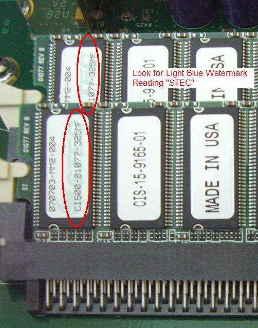
The images below show examples of the two different DIMM labels used by the vendor. These two labels identify the affected DIMMs that need to be replaced.
Figure 1 shows the first of two watermarks on the affected DIMMs.
Figure 2 shows the second watermark of the affected DIMMs.
Figure 3 shows the close-up of the watermark label identifying affected DIMMs.
Figure 1 - Affected DIMMs and 1st Watermark type
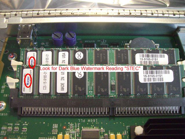
Figure 2 - Affected DIMMs and 2nd Watermark type
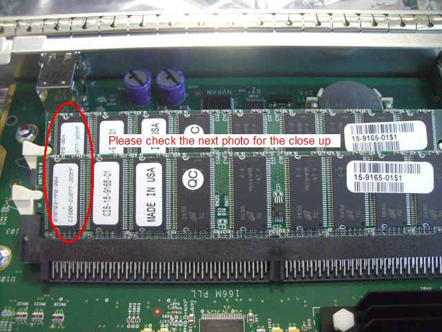
Figure 3 - DIMMs Close-up Image of Figure 2 Showing the Watermark Beneath the Serial Number
B. Request Replacement DIMMs
If you are a Reseller supported customer, contact your Reseller to obtain DIMM replacements (Product ID: DS-DIMM1=). If you are not a Reseller supported customer, please contact the Cisco TAC and reference this FN to order your replacement DIMMs.
Each replacement DIMM order contains 2 DIMMS (which is sufficient for 1 Supervisor). Please place your replacement order based on the quantity of the Supervisors affected.
Note - Please use the SN of the Supervisor when requesting replacement DIMMs.
C. Replacing DIMMs
After receiving the replacement DIMMs, follow the instructions in this section to remove the Supervisor 2 module from the chassis and replace the DIMMs. Ensure the module you are removing is the Standby Supervisor. If both Supervisors are affected, please replace the DIMM on the Standby first. If the active Supervisor is affected, please follow the instruction below.
How to place your active supervisor in Standby mode
Identify the Supervisor-2 module that needs the DIMM's replaced and ensure it is the standby supervisor via the show module command. If the supervisor is the active supervisor you will need to perform the system switchover command to make the current active Supervisor come up in Standby mode. Make sure the Standby Supervisor is in "ha-standby" by repeating the show module command before starting the replacement steps.
Example of systems switchover command shown below:
switch# system switchover
Note - Prior to replacing DIMM's in Cisco MDS 9509 and 9506 Directors, shut down the crossbar switching fabric functionality in the Supervisor module by using the ?out-of-service module slot? command (where slot refers to the slot number for the Standby Supervisor-2 module where the integrated crossbar is located).
Example of out-of-service module slot command shown below:
switch# out-of-service module x

where x = the standby supervisor slot
Caution - When handling switch components, wear an ESD strap and handle modules by the carrier edges only. An ESD socket is provided on the chassis. For the ESD socket to be effective, the chassis must be grounded either through the power cable, the chassis ground, or metal-to-metal contact with a grounded rack.
Click here for demonstration video of the steps listed below.
Step 1 - Make sure the Supervisor is in standby mode
Step 2 - Attach a grounding strap
Step 3 - Disconnect any network interface cables (for example, the Console cable and the Ethernet cable) attached to the module.
Step 4 - Loosen the two captive screws on the left and right side of the module.
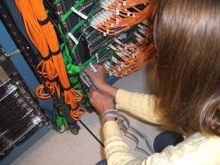
Step 5 - Remove the standby supervisor from the chassis as follows:
5a. Place your thumbs on the left and right ejector levers and simultaneously rotate the levers outward to unseat the module from the backplane connector.
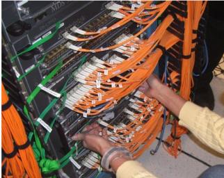
5b. Grasp the front edge of the module and slide the module partially out of the slot. Place one hand under the module to support the weight of the module. Do not touch the module circuitry.
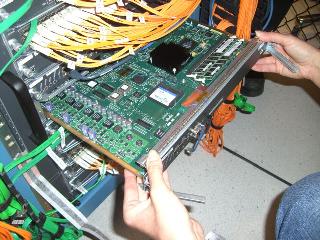
Step 6 - Place the module on an antistatic mat or antistatic foam.
Step 7 - Attach a grounding strap to the module.
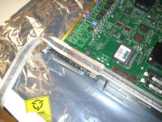
Step 8 - Identify the DIMM on the module. The position of the DIMM is in the front-right side of the module.
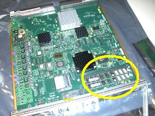
Step 9 - Remove the DIMM by pressing the left and right side levers outward. Always replace both DIMMs on the Supervisor.
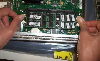
Step 10 - Install the new DIMM and then press inward until the left and right side levers snap into place.
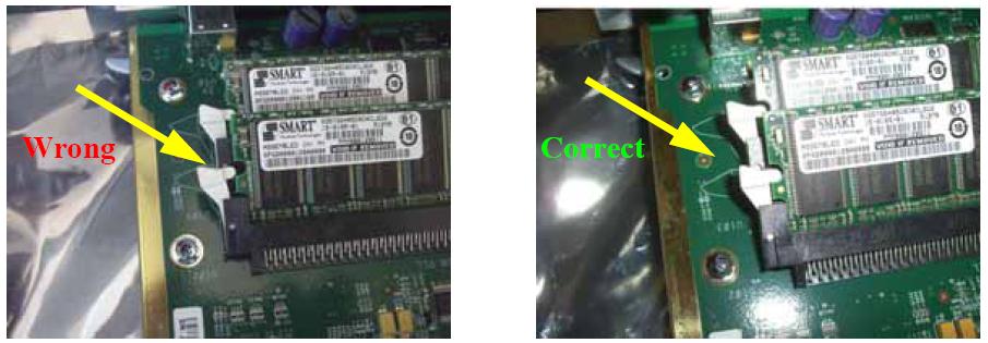
Step 11 - Insert the Supervisor 2 module back into the chassis.
Step 12 - Press the left and right-side ejector levers inward.
Step 13 - Tighten the two captive screws on the left and right side of the module.
Step 14 - Reconnect any interface cables that were disconnected in Step 2.
How To Identify Affected Products
How To Identify Affected DIMMs
The images below show examples of the two different DIMM labels used by the vendor. These two labels identify the affected DIMMs that need to be replaced.
Figure 1 shows affected DIMMs. Figure 2 shows a close-up of Figure 1 showing the watermark beneath the serial number on the affected DIMMs. Figure 3 shows the second type of label identifying affected DIMMs.
Figure 1 - Affected DIMMs

Figure 2 - Close-up Image of Figure 1 Showing the Watermark Beneath the Serial Number

Figure 3 - Affected DIMMs

For More Information
If you require further assistance, or if you have any further questions regarding this field notice, please contact the Cisco Systems Technical Assistance Center (TAC) by one of the following methods:
Receive Email Notification For New Field Notices
Cisco Notification Service—Set up a profile to receive email updates about reliability, safety, network security, and end-of-sale issues for the Cisco products you specify.
Unleash the Power of TAC's Virtual Assistance
 Feedback