Field Notice: FN - 64025 - Adhere to Hardware Installation Guide - WS-C3560CX and WS-C2960CX
Available Languages
NOTICE:
THIS FIELD NOTICE IS PROVIDED ON AN "AS IS" BASIS AND DOES NOT IMPLY ANY KIND OF GUARANTEE OR WARRANTY, INCLUDING THE WARRANTY OF MERCHANTABILITY. YOUR USE OF THE INFORMATION ON THE FIELD NOTICE OR MATERIALS LINKED FROM THE FIELD NOTICE IS AT YOUR OWN RISK. CISCO RESERVES THE RIGHT TO CHANGE OR UPDATE THIS FIELD NOTICE AT ANY TIME.
Revision History
| Revision | Date | Comment |
|---|---|---|
1.0 |
21-SEP-2015 |
Initial Public Release |
Products Affected
| Products Affected |
|---|
WS-C2960CX-8PC-L |
WS-C2960CX-8TC-L |
WS-C3560CX-12PC-S |
WS-C3560CX-12PD-S |
WS-C3560CX-12TC-S |
WS-C3560CX-8PC-S |
WS-C3560CX-8TC-S |
Problem Description
The screws might not be installed to the correct depth as described in the Hardware Installation Guide for WS-C3560CX and WS-C2960CX switches that are mounted to a desk, shelf, or wall with mounting screws (without a mounting tray). This installation error, coupled with appreciable force in order to mount the switch, might cause the insulator to be punctured which exposes a voltage circuit. When the screw and voltage circuit touch, a short circuit between the voltage part and the chassis ground occurs. This might result in an electrical shock for a very short time period before the unit fails.
Background
Potentially impacted customers: Only customers who will mount or remount the switch to a desk, shelf, or wall with mounting screws (without a mounting tray).
Customers not impacted: Customers who have mounted the switch with a mounting tray, mounted the switch in a rack, or already mounted the switch to a desk, shelf, or wall with mounting screws (and the switch currently works).
Problem Symptoms
If the switch is mounted to a desk, shelf, or wall with mounting screws (without a mounting tray), this could occur when:
- The installer did not follow the mounting instructions, as described in the Hardware Installation Guide, which state the required screw depth per the provided screw template.
- The installer might have energized the product prior to mounting.
- Dependent upon on the screw depth, when the installer uses an appreciable force (30 lbs. or more) in order to mount the switch the insulator might be punctured which exposes a voltage circuit. When the screw and voltage circuit touch, a short circuit between the voltage part and the chassis ground occurs. This might result in an electrical shock for a very short time period before the unit fails.
If mounting instructions are not followed, a low risk of a potential electric shock exists.
Workaround/Solution
The wall-mounting instructions can be found in the Hardware Installation Guide.
The desk- or shelf-mounting instructions are very similar and can also be found in the Hardware Installation Guide.


Cisco strongly recommends to use the mounting tray for safety reasons.
For customers who want to install the switch with the mounting tray (CMPCT-MGNT-TRAY), contact the Technical Assistance Center (TAC) for assistance.
How To Identify Affected Products
Customers who have mounted the switch with a mounting tray, mounted the switch in a rack, or already mounted the switch to a desk, shelf, or wall with mounting screws (and the switch currently works) are not impacted.
Customers who intend to mount/remount the switch MUST follow the mounting instructions as described in the Hardware Installation Guide and use the screw template provided with the product (or a mounting tray (CMPCT-MGNT-TRAY) if purchased).
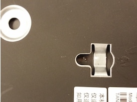
Failure to follow the mounting instructions could result in insulation damage (as shown in Figures A and B) due to excessive force while mounting.

Figure A. The power supply through-hole pins
are exposed.

Figure B. The test pin touches the through-hole pins.
For More Information
If you require further assistance, or if you have any further questions regarding this field notice, please contact the Cisco Systems Technical Assistance Center (TAC) by one of the following methods:
Receive Email Notification For New Field Notices
Cisco Notification Service—Set up a profile to receive email updates about reliability, safety, network security, and end-of-sale issues for the Cisco products you specify.
Contact Cisco
- Open a Support Case

- (Requires a Cisco Service Contract)
This Document Applies to These Products
Unleash the Power of TAC's Virtual Assistance
 Feedback