Introduction
A Hyperflex stretched cluster is a single cluster with geographically distributed nodes. Both sides of the cluster act as primary for certain user VMs. The data for these VMs is replicated synchronously on the other site. Stretched clusters enable you to access the entire cluster even if one of the sites were to completely go down. Typically these sites are connected with a low latency, dedicated, high-speed link between them.
HyperFlex Stretched Cluster enables you to deploy an Active-Active disaster avoidance solution for mission critical workloads requiring high uptime (near zero Recovery Time Objective) and no data loss (zero Recovery Point Objective).
Prerequisites
Requirements
- All the nodes in the cluster should be of the same M5 models (All HX220 M5) or (HX 240 M5)
- Only M5 node are supported in sctretch Clusters
- Stretch clusters is only supported on ESXi HX platforms
- Each site should have a minimum of 2 nodes
- ALL the VLANs used on both clusters have to be SAME
- Stretch cluster configuration requires a Witness VM
- Stretch Clustres require the same number of IP addresses that is needed for a six node cluster
- Only one instance of vCenter is used for a stretch cluster
- vCenter with DRS and HA is required for the stretch cluster to work properly
Components Used
- HX Installer
- Cisco HX M5 servers
- VMWare vCenter
- Cisco UCSM
- VMWare ESXi
Other Requirements
Configure
Network Diagram

Configurations
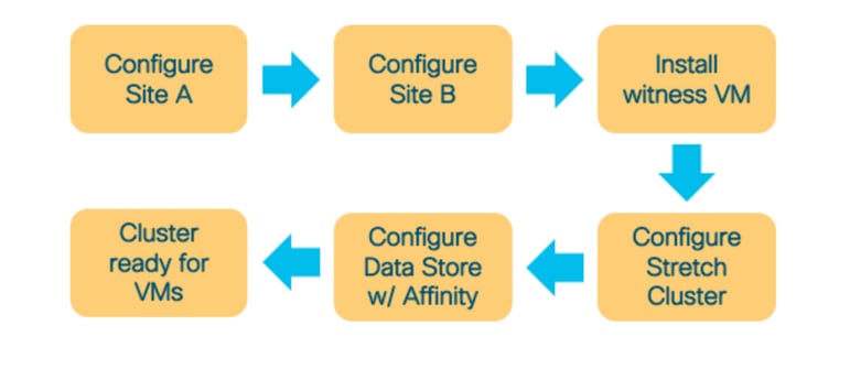
All the configuration for a stretch cluster will be done from a single HX installer. The workflow for stretch cluster install steps is as shown below:
Configure Site A
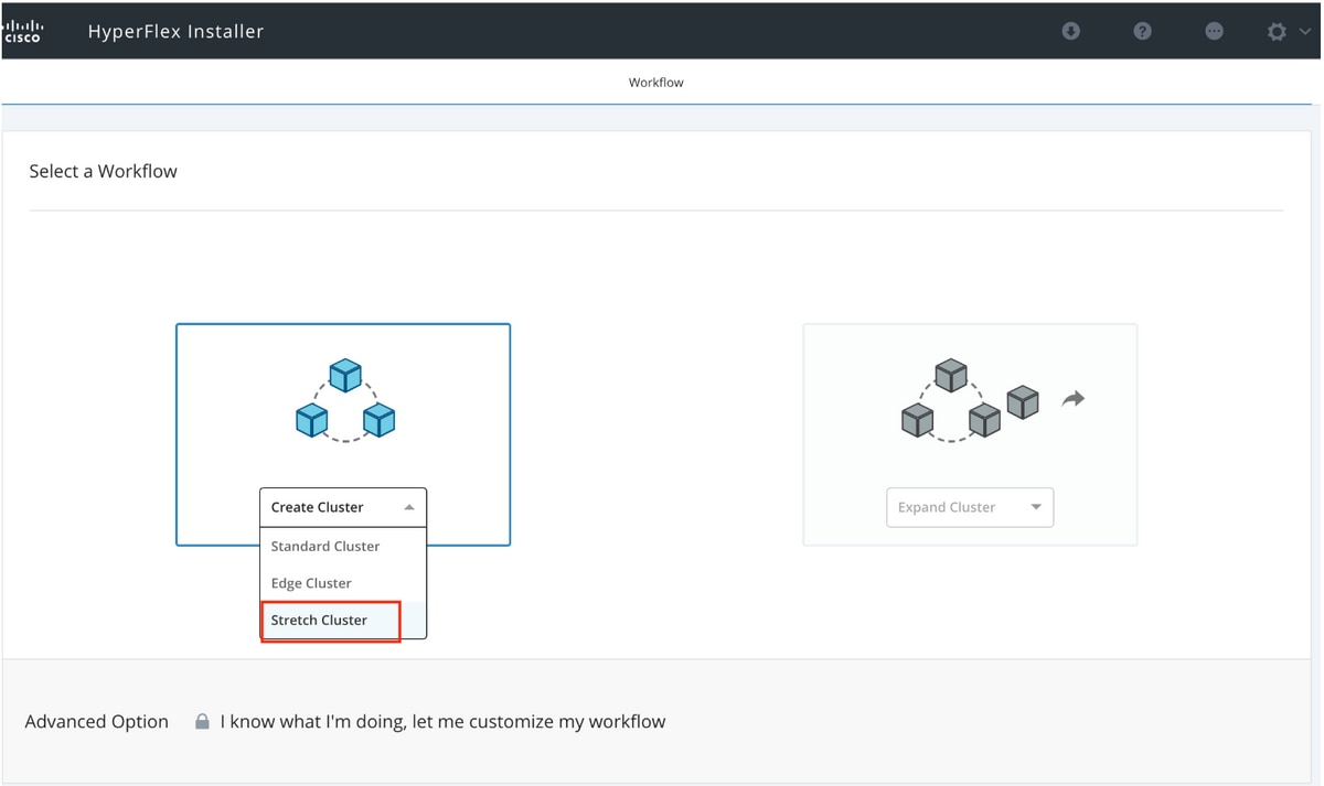
Step 1. Log on to the respective assigned HX installer to start the cluster configuration. If the installer is still showing the previous install status click on the wheel in the bar above and select Start Over to begin a fresh install. In the Select a Workflow --> Create Cluster -->(select) Stretch Cluster.
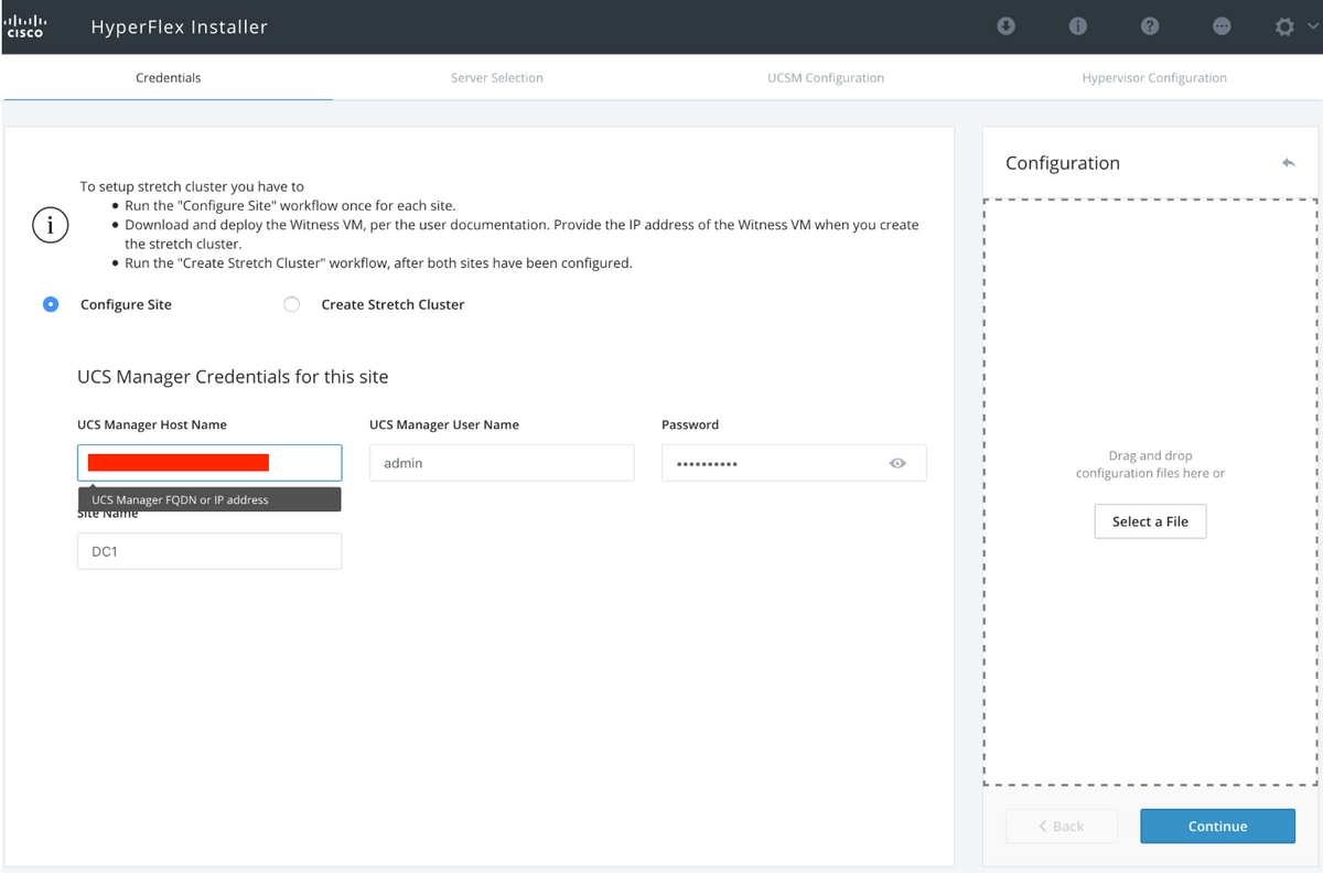
Step 2. In the configure site workflow enter the UCSM credentials and DC in the Site Name. Then click Continue.
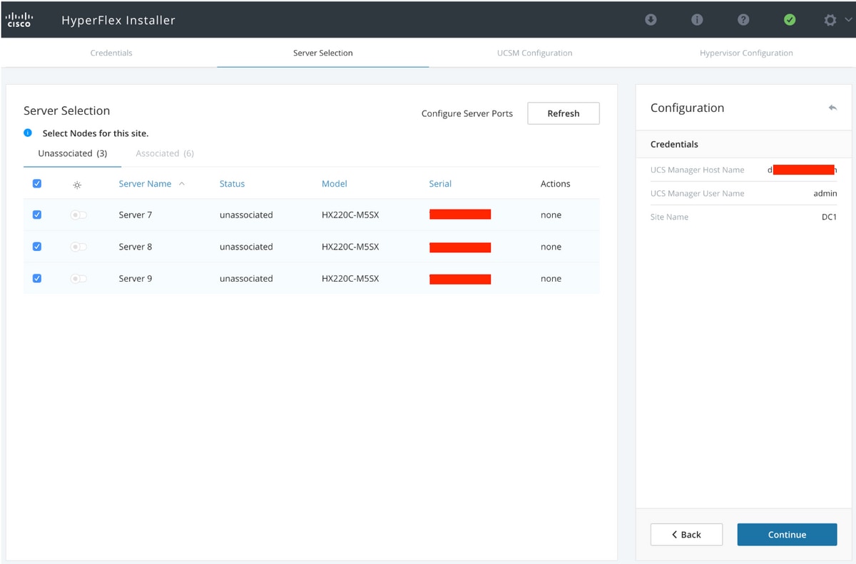
Step 3. In the server selection, select the source servers and click Continue
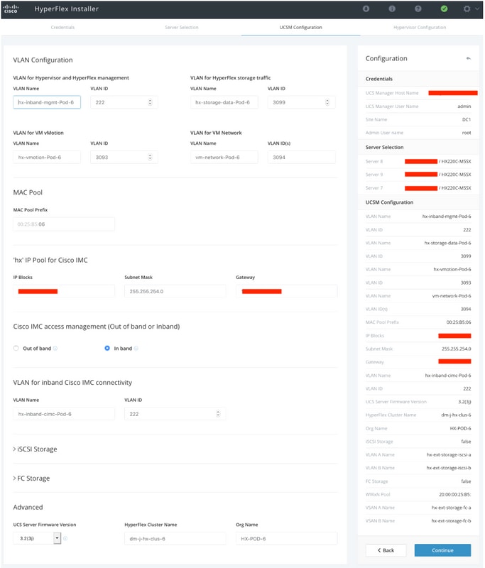
Step 4. Under the UCSM configuration section enter the VLAN ID and VLAN names. In this case we have used Inband for CIMC. Click Continue
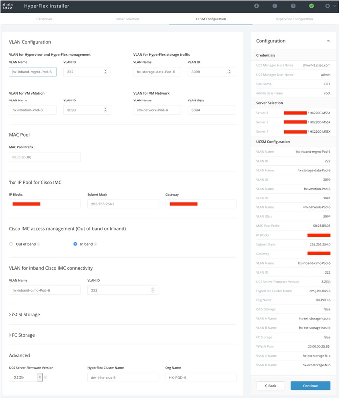
Step 5. In the Hypervisor Configuration section provide all the requested information. Then click Configure Site to begin site configuration.
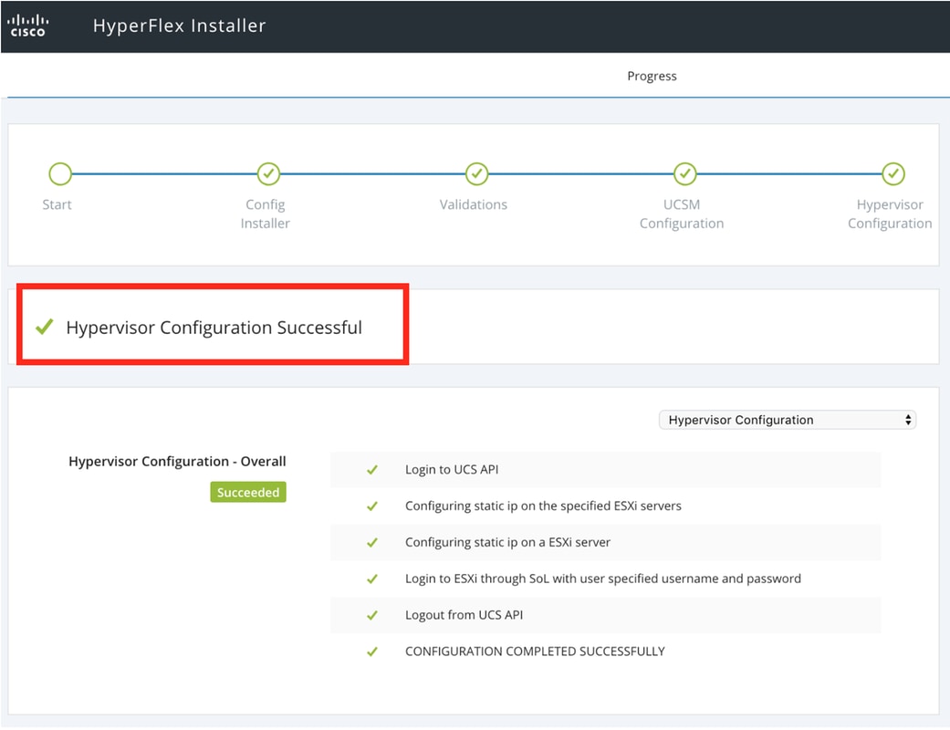
Step 6. Confirm that the Site A Hypervisor Configuration is Successful.
Configure Site B
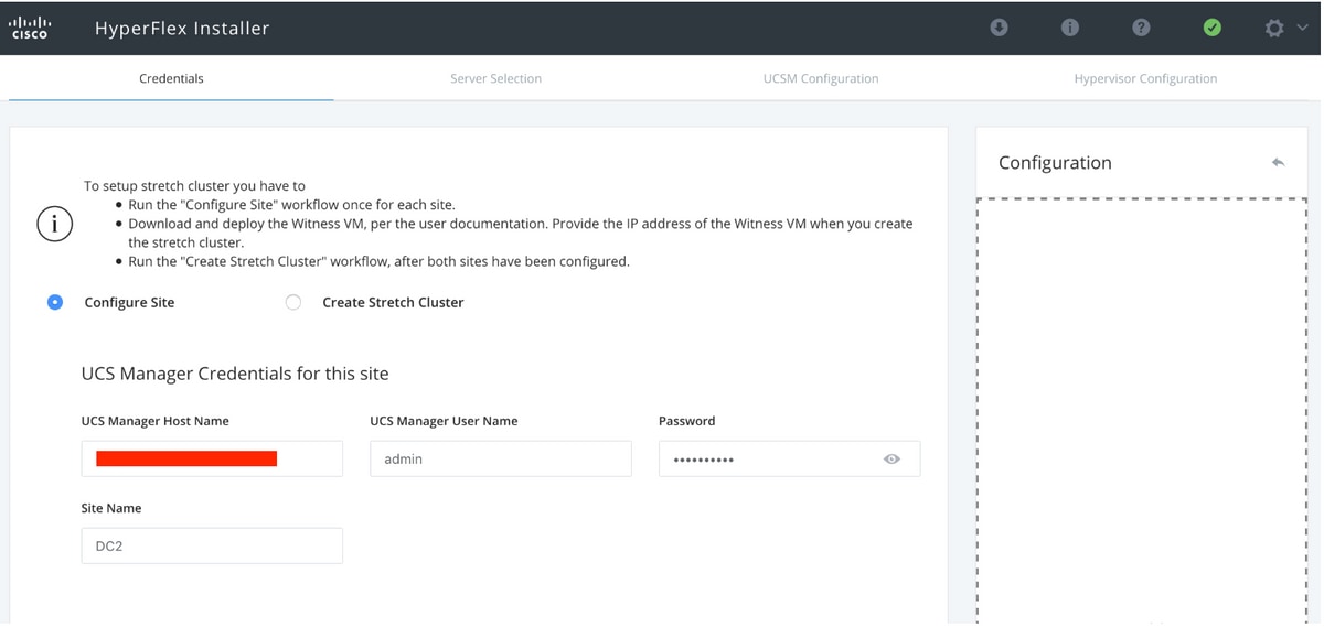
Step 1. Click on the wheel and select Configure Site to beigin the Site B configuration as shown below.

Step 2. In the Configure Site workflow enter the Target UCSM credentials and Target DC in the Site Name. Then click Continue.
Step 3. In the server selection, select the source servers and click Continue
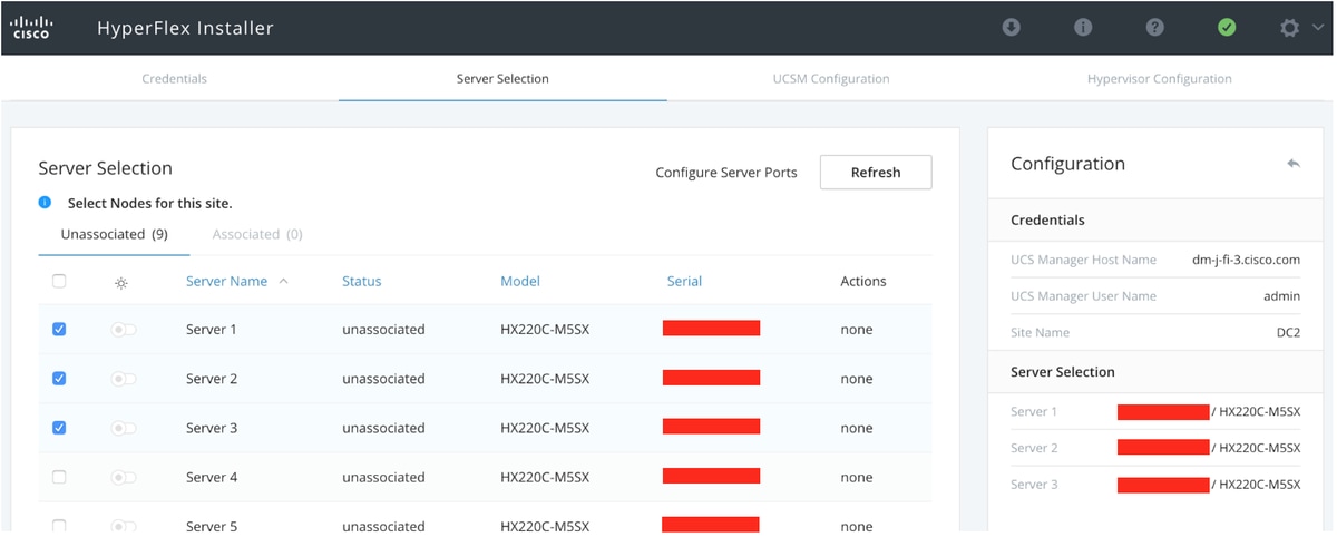
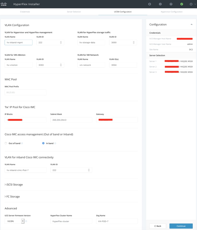
Step 4. Under the UCSM configuration section enter the VLAN ID and VLAN names. In this case we have used Inband for CIMC. Click Continue
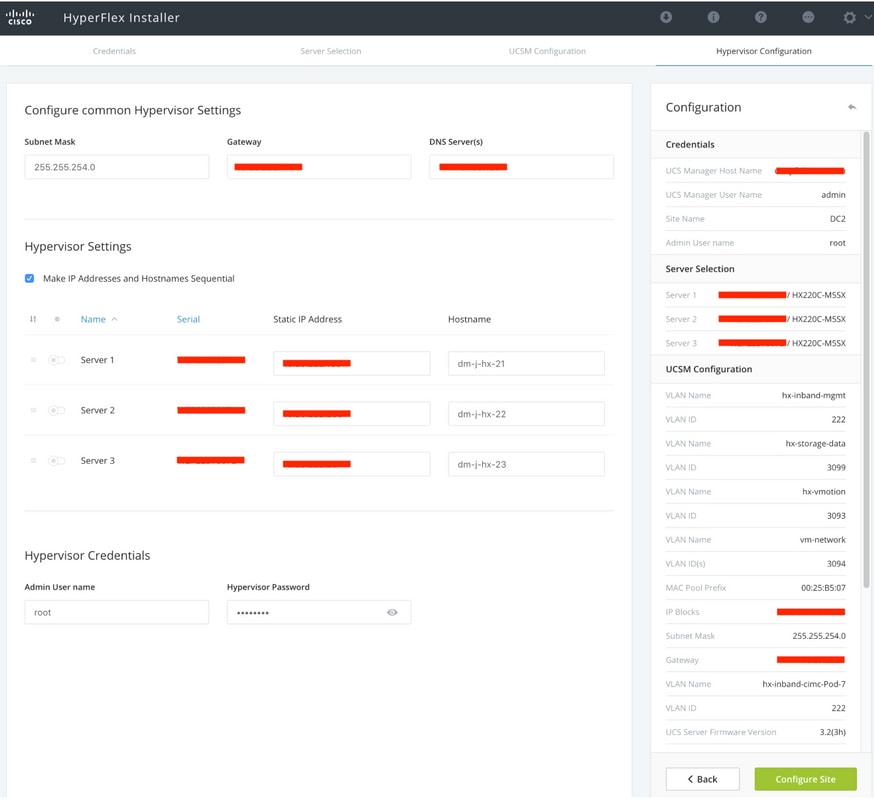
Step 5. In the Hypervisor Configuration section provide all the requested information. Then click Configure Site to begin site configuration.
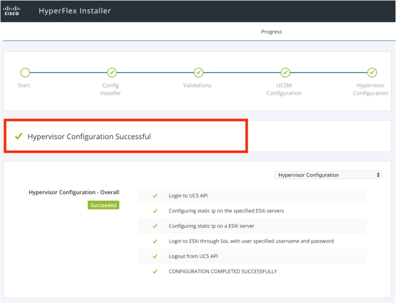
Step 6. Confirm that the Site B Hypervisor Configuration is Successful.
HX Witness VM Deployment
- This is an important step before proceeding further. The HX witness VM needs to be up and running and reachable for the install to succeed.
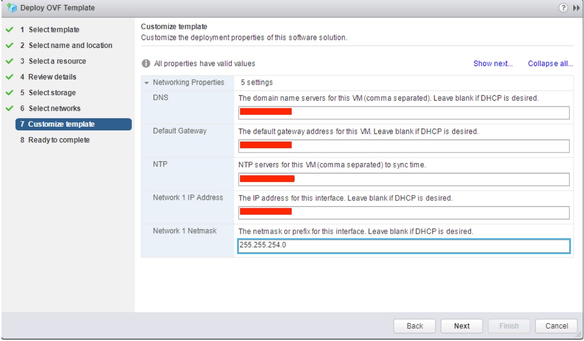
- An OVA image needs to be deployed on a ESXi host.
- Please test connectivity to this VM and make sure login works.
- Refer the below for OVA install properties.
Create Stretch Cluster
Step 1.
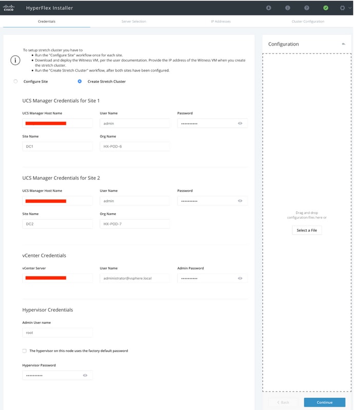
- To begin configuring the stretch cluster navigate to the Wheel on the installer and select Create Stretch Cluster to begin the stretch cluster configuration.
- In the credentials screen provide the source (Site A) and Target (Site B) UCSM and its credentials, Site name, UCSM Org name, vCenter and Hypervisor credentials. Click Continue to proceed to the Server Selction screen.
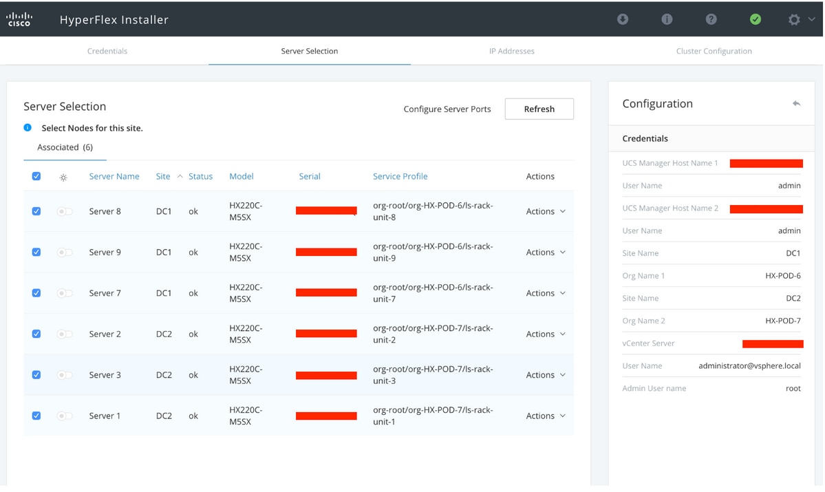
Step 2. Make sure that all the servers (both source and target servers) are show as selected. Then click Continue,
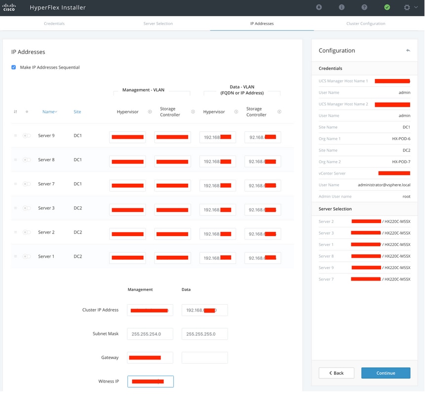
Step 3. In the IP Address Section, provide the Hypervisor and Storage controller mgmt (Public routable) IP as well as their DATA (Private non routable) IP. Also, provide the cluster IP for both Management and Data netwoks. Click Continue.
Step 4. Under the Cluster Configuration, enter the Controller VM passwords, vCenter configuration details, system services details. Under the Advanced Networking section configure same Management and Data VLANs for both sites. Then click Start to begin the cluster configurations.
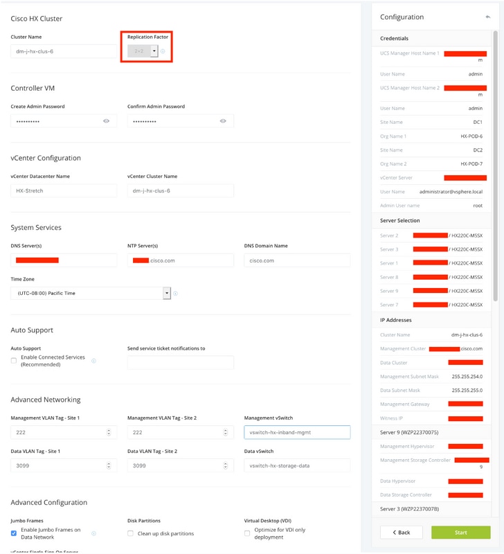
Step 5. Confirm that the Cluster creation completes Successfully.
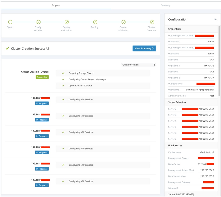
Verify
Datastore creation
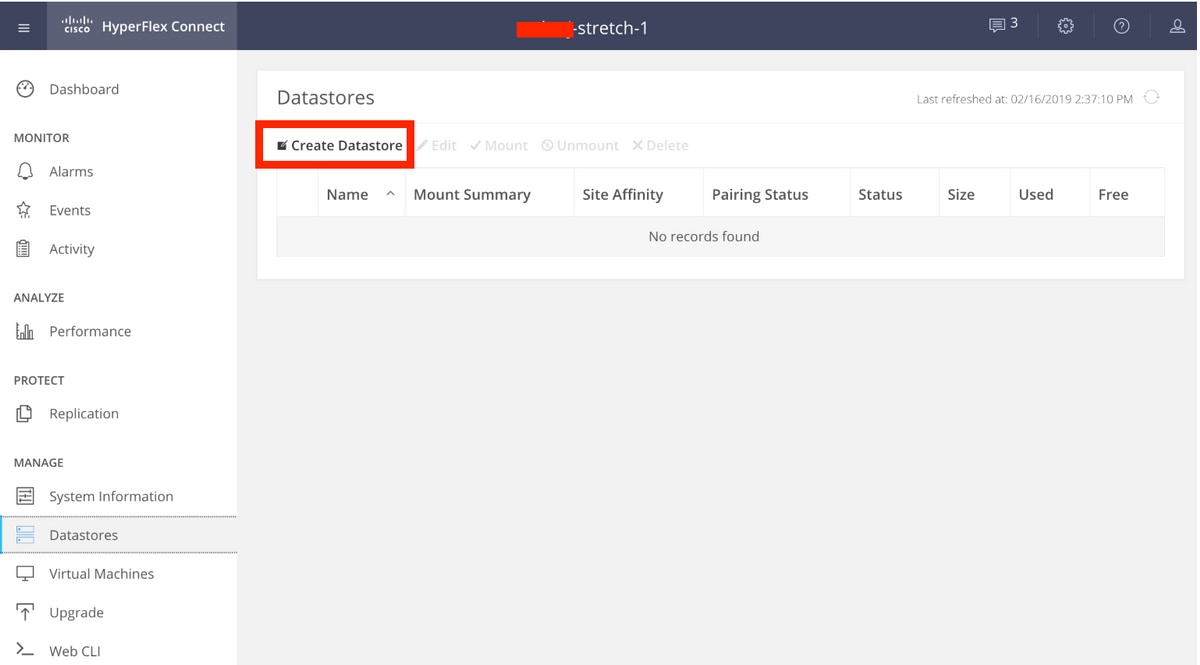
Step 1. The datastore creation on a stretch cluster is similar to the a datastore creationon a normal cluster. The only difference is while creating a datastore in a stretch cluster is defining site affinity. In the Hyperflex Connect UI navigate to the Datastores and click Create Datastore
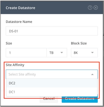
Step 2. Create a datastore and slect its size. Then in the additional step, under the Site Affinity drop down select one of the two sites. then click Create Datastore
Step 3. Confirm the status ofthe newly created datastore that it shows as MOUNTED and also shows its site affinity.

