SAN Boot from HyperFlex iSCSI: UCS Servers Configuration Examples
Available Languages
Download Options
Bias-Free Language
The documentation set for this product strives to use bias-free language. For the purposes of this documentation set, bias-free is defined as language that does not imply discrimination based on age, disability, gender, racial identity, ethnic identity, sexual orientation, socioeconomic status, and intersectionality. Exceptions may be present in the documentation due to language that is hardcoded in the user interfaces of the product software, language used based on RFP documentation, or language that is used by a referenced third-party product. Learn more about how Cisco is using Inclusive Language.
Contents
Introduction
This document describes the configuration of HyperFlex (HX), a standalone Unified Computing System (UCS) Server, UCS Server in Intersight Managed Mode (IMM), and UCS Managed Server in order to do a Storage Area Network (SAN) Boot from HyperFlex Internet Small Computer Systems Interface (iSCSI).
Contributed by Joost van der Made, Cisco TME, and Zayar Soe, Cisco Software QA Engineer.
Prerequisites
Requirements
Cisco recommends that you have knowledge of these topics:
- The UCS is initialized and configured; refer to the UCS configuration guide
- HyperFlex cluster is created; refer to HyperFlex configuration guide
- iSCSI network is configured with a VLAN; refer to HyperFlex configuration iSCSI configuration part (record those iSCSI target IP addresses, VLAN, Challenge Handshake Authentication Protocol (CHAP) information in order to use in this configuration guide)
- The Network Interface Controller or Card (NIC) cards must be Cisco Virtual Interface Card (VIC) 1300 or 1400 series
Components Used
The information in this document is based on these software and hardware versions:
- HyperFlex Data Platform (HXDP) 4.5(2a)
- UCS 220 M5 servers
- UCS firmware 4.1(3c)
The information in this document was created from the devices in a specific lab environment. All of the devices used in this document started with a cleared (default) configuration. If your network is live, ensure that you understand the potential impact of any command.
Background Information
A stateless server is easy in order to replace or expand, and it is only possible when the Boot Drive isn’t local. In order to achieve this result, boot the server from a device outside the server, and SAN Boot makes this possible.
This document describes how to boot from iSCSI on HyperFlex using the Cisco UCS platform and how to troubleshoot. When this document talks about SAN Boot, the iSCSI Protocol is used in order to boot the server from a HyperFlex iSCSI Target Logical Unit Number (LUN). Fibre-channel connections are not part of this document.
In HXDP 4.5(2a) and later, the VIC1300 and VIC1400 are qualified to be iSCSI Initiators for HyperFlex iSCSI Targets. UCS Servers with this type of VICs can perform a SAN Boot from HyperFlex iSCSI.
This document explains the configuration of HyperFlex, a standalone UCS Server, UCS Server in IMM, and UCS Managed Server in order to do a SAN Boot from HyperFlex iSCSI. The last part covers the installation and configuration of Windows and ESXi Operating System (OS) with Multipath I/O (MPIO) Boot from SAN.
The target audience is UCS and HX administrators who have a basic understanding of UCS configuration, HX configuration, and OS installation.
Configure
High-Level Overview of the SAN Boot from HyperFlex iSCSI
HyperFlex iSCSI in a nutshell:
At the time of the configuration of the iSCSI network on the HyperFlex cluster, a HyperFlex iSCSI Cluster IP address is created. This address can be used in order to discover the Targets and LUN by the initiator. The HyperFlex Cluster determines which HyperFlex node connects. If there is a failure or one node is very busy, HyperFlex moves the Target to another node. A direct log-in from the initiator to a HyperFlex node is possible. In this case, the redundancy can be configured on the Initiator side.
The HyperFlex Cluster can consist of one or many HyperFlex Targets. Every Target has a unique iSCSI Qualified Name (IQN) and can have one or multiple LUNs, and these LUNs automatically get a LUN ID assigned.
The Initiator IQN is put in an Initiator Group linked to a HyperFlex Target where a LUN resides. The Initiator Group can consist of one or more initiator IQNs. When an OS is already installed on a LUN, you can clone it and use it multiple times for a SAN Boot of different servers, which saves time.
Note: A Windows OS cannot be cloned due to its behavior.
Configure HyperFlex
The configuration of HyperFlex for all three scenarios is the same. The IQN in the UCS Server configuration can be different compared to this section.
Prerequisites: Before you configure the steps mentioned in this document, a joint task must have already been done. These steps are not explained in this document.HyperFlex iSCSI Network is configured in HyperFlex. See HyperFlex Admin Guide about the steps.
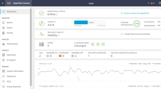
Step 1. Open the HX-Connect, choose iSCSI as shown in this image:
Step 2. Create a new HyperFlex iSCSI Target as shown in this image:

In this configuration example, we don’t use authentication. Give the Target Name a name without _ (Underscore) or other special characters. In these examples, CHAP authentication is not configured. For security reasons, it is possible in order to configure CHAP authentication. In the examples to install a Windows OS and ESXi on the BootFromSAN LUN, CHAP authentication is configured.
Step 3. Create a LUN within this Target as shown in this image:
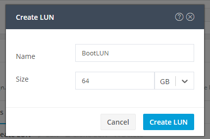
The name is just for your reference. Choose the appropriate size of the LUN. HyperFlex does not support LUN masking, and LUN IDs are generated automatically.
Step 4. Create an Initiator Group (IG) on HyperFlex with the IQN of the Initiator as shown in this image:
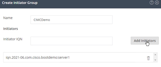
Decide a name for the IG. If you do not know the IQN of the Initiator at this moment, just add any valid IQN to this IG. Later you can delete it and add the correct initiator IQN name. Document the IG, in order to quickly find the Initiator name when you must change it.
In an IG, one or multiple Initiators IQN can be added.
If the initiator is outside of the HyperFlex iSCSI subnet, run hxcli iscsi allowlist add -p <ip address of the initiator> command via the controller or HX WebCLI.
In order to verify if this IP address was added to the allowlist, run hxcli iscsi allowlist show command.
Step 4.1. Click Create Initiator Group as shown in this image:

Step 5. Link the IG with the HyperFlex Target. A HyperFlex Target with LUNs is created, and the IG is created. The last step for the HyperFlex configuration is to Link the Target with the IG.Choose the IG and select Linked Targets as shown in this image:
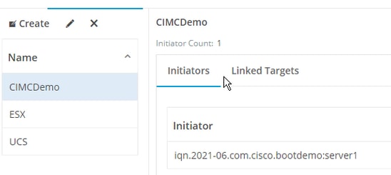
SelectLink and choose the correct HyperFlex Target.
Step 5.1. Document HyperFlex Target IQN and LUN ID. Later, the HyperFlex Target IQN gets configured at the initiator. Choose the newly created Target and document the IQN.In this example, it is iqn.1987-02.com.cisco.iscsi:CIMCDemoBoot as shown in this image:
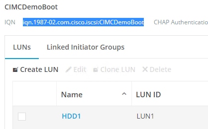
The LUN ID at this target must also be documented and used later at the Initiator configuration. In this example, the LUN ID is LUN1.
If multiple targets are configured at the cluster, LUNs can have the same LUN ID on different HyperFlex Targets IQNs.
Configure UCS Standalone Server - CIMC
The server only has a Modular LAN-on-Motherboard (MLOM) with a network connection in this example. If there are multiple network adapters, please select the correct one. The procedure is the same as described here:
Prerequisites: Before you configure the steps mentioned in this document, a joint task must have already been done. These steps are not explained in this document.
- HyperFlex iSCSI Target, LUN, and IG are configured and linked
- CIMC is configured with an IP address that is reachable from a browser
Network Diagram:
The physical network topology of the setup is as shown in this image:
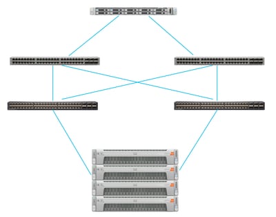
The UCS Standalone Server is connected via the MLOM to two Nexus switches. The two Nexus switches have a VPC connection to the Fabric Interconnect. Each HyperFlex node connects the network adapter to Fabric Interconnect A and B. For the SAN Boot, a Layer 2 iSCSI VLAN network is configured.
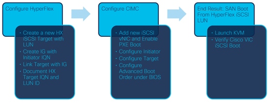
Workflow: The steps to be followed in order to configure SAN Boot from HyperFlex iSCSI LUN are as shown in this image:
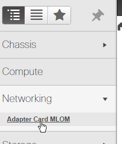
Step 1. Configure the Network Adapter Card. Open CIMC in a browser and choose Networking > Adapter Card MLOM as shown in this image:
Step 2. Choose vNICs as shown in this image:

By default, there are already two vNICs configured. Leave them as they are as shown in this image:
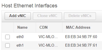
Step 3. Choose Add vNIC as shown in this image:
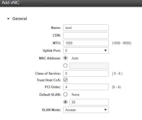
This new vNIC transports the iSCSI traffic from the HyperFlex cluster to the UCS Server. In this example, the server has a Layer 2 iSCSI VLAN Connection. The VLAN is 20, and the VLAN Mode must be set to Access.
Step 3.1. Ensure Enable PXE Boot is checked as shown in this image:
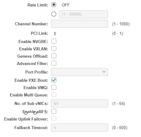
Step 3.2. Now you can add this vNIC. Use the Add vNIC option as shown in this image:

Step 4. On the left, choose the new created iscsi vNIC as shown in this image:
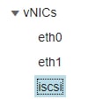
Step 4.1. Scroll down to the iSCSI Boot Properties and expand Initiator as shown in this image:
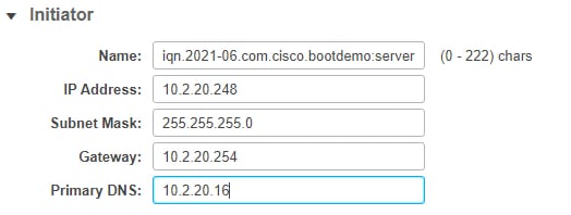
The Name is the IQN of the Initiator. You can create your IQN as described in RFC 3720. The IP address is which IP address the UCS Server gets for the iSCSI vNIC. This address must communicate with the HyperFlex iSCSI Cluster IP address. The HyperFlex Target doesn’t have authentication so leave the rest blank as shown in this image:
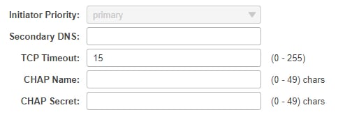
Step 4.2. Configure the Primary Target as shown in this image:

The Name of the Primary Target is the HyperFlex Target which is linked to the IG with the IQN of this Initiator. The IP address is the HyperFlex iSCSI Cluster IP address.
Step 4.3. Ensure the Boot LUN is the correct one as shown in this image:

Verification can be done in order to see the LUN ID of the LUN at the HyperFlex iSCSI Target. Click the Save Changes and OK button as shown in these images:


Prerequisites: Before you configure the steps mentioned in this document, a joint task must have already been done. A Service Profile was already created and assigned to a server. This step is not explained in this part of the document.
Step 1. Configure the CIMC Boot Order. Open the server CIMC and choose to Compute as shown in this image:
Step 1.1. Choose BIOS>Configure Boot Order > Configure Boot order as shown in these images:


Step 2. For iSCSI, we must use the Advanced Tab and choose Add iSCSI Boot as shown in these images:
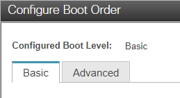
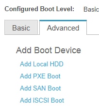
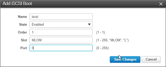
Step 2.1. When you add iSCSI boot, the Name is for your reference.Ensure the Order is set to the lowest number, so it tries to boot from it first.The Slot in this example is MLOM. The port is set automatically to 0 as shown in this image:
Verify:
SAN Boot from HyperFlex iSCSI LUN. Reboot the server and verify that the BIOS sees the HyperFlex iSCSI LUN. When the Boot Order is set up correctly, it does a SAN boot from HyperFlex iSCSI LUN. On the BIOS screen, you see the Cisco VIC Simple Network Protocol Driver, and it shows the IQN of the HyperFlex Target LUN with the size of the LUN as shown in this image:
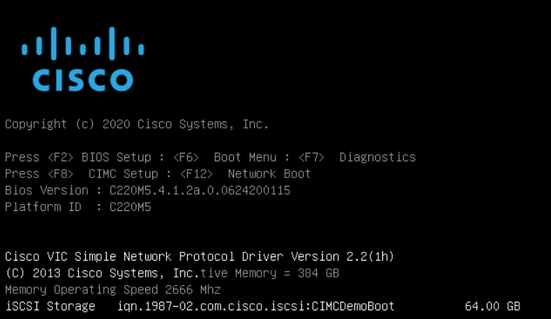
If the HyperFlex Target has multiple LUNs, they must be shown here.
When there is no OS installed on the LUN, you need to install it via vMedia or manually via the Keyboard, Video, Mouse (KVM).
Configure UCS Manager
Network Diagram:
The physical network topology of the setup is as shown in this image:
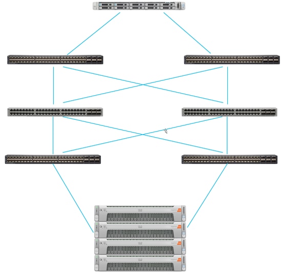
The UCS Server is connected via Fabric Interconnects connected to the Nexus switches. The two Nexus switches have a VPC connection to the HyperFlex Fabric Interconnects. Each HyperFlex node connects the network adapter to Fabric Interconnect A and B. In this example, the iSCSI goes over different VLANs to show how you configure HyperFlex for this network situation. It is recommended that you eliminate Layer 3 routers and only use Layer 2 iSCSI VLANs to prevent this situation.
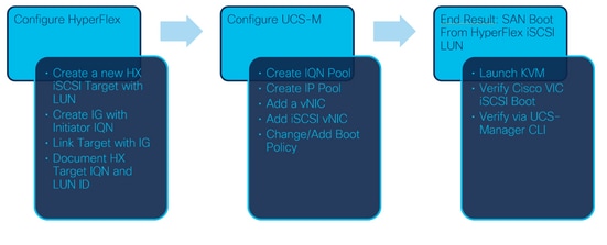
Workflow:
The steps to be followed in order to configure SAN Boot from HyperFlex iSCSI LUN are as shown in this image:
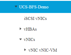
Step 1. Currently, there are no iSCSI vNICs configured on the Service Profile. There is only one entry under vNICs as shown in this image:
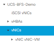
Step 1.1. Choose vNICs and clickAdd to add another vNIC for the iSCSI boot traffic as shown in these images:
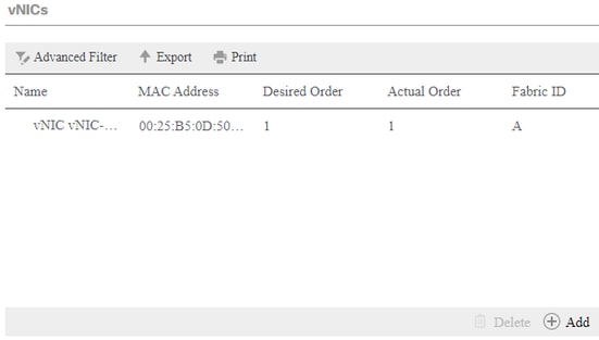
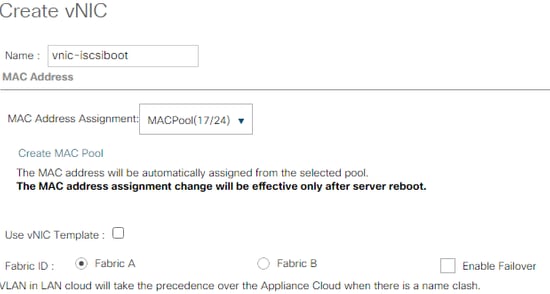
The Name is the name of the vNIC, and this name is needed later in the Boot Order Policy.
Step 1.2. Choose an already created MACPool.You can choose to have multiple vNICs for iSCSI over Fabric-A and Fabric-B or in order to select Enable Failover.In this example, the iSCSI vNIC is only connected over Fabric A as shown in this image:
Step 1.3. Choose the VLAN which the iSCSI traffic is supposed to use. This example has the same iSCSI VLAN used by HyperFlex iSCSI Network as shown in this image:
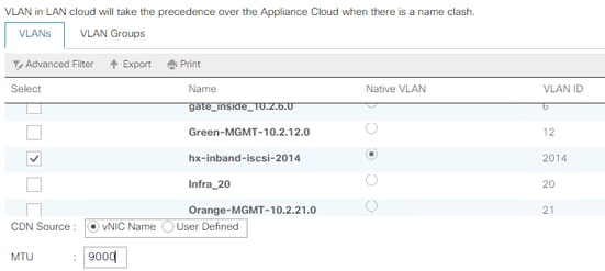
Note: Ensure this iSCSI VLAN is the Native VLAN. This is only a native VLAN from the server to the Fabric Interconnect and this VLAN doesn’t have to be native outside of the Fabric Interconnects.
The best practice for iSCSI is to have Jumbo Frames, which have an MTU size of 9000. If you configure Jumbo Frames, ensure it is end-to-end Jumbo Frames. This includes the OS of the Initiator.
Step 1.4. Click Save Changes and Yes as shown in these images:

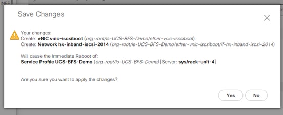
There are now two vNICs for the Service Profile.
Step 2. Add an iSCSI vNIC. Choose iSCSI vNICs and select Add as shown in these images:
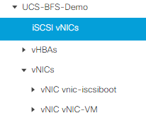
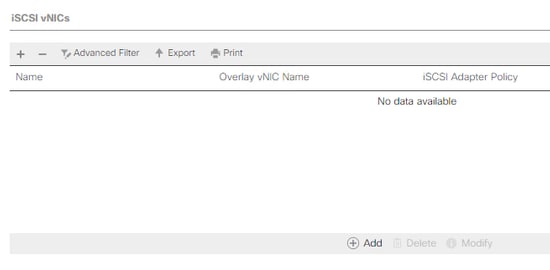
An iSCSI vNIC is now created.
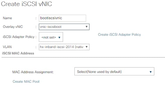
Note: iSCSI vNIC is an iSCSI Boot Firmware Table (iBFT) placeholder for iSCSI boot configuration. It is not actual vNIC, and therefore a vNIC that underlies must be selected. Please do not assign a separate MAC address.
Step 2.1. The Name is just an identifier. In VLAN, there is only a choice of one VLAN, which must have been the Native VLAN.Leave the MAC address Assignment in order to Select(None used by default) as shown in this image:
Step 2.2. Change/Add Boot Policy. On the Service Profile, choose Boot Orderas shown in this image:

Step 2.3. You can modify the Boot Policy only when other servers don’t use this Boot Order Policy. In this example, a new Boot Policy is created. The Name is the name of this Boot Policy. If the BOOT LUN doesn’t have any OS installed, ensure you choose, for instance, a Remote CD-ROM. This way, the OS can be installed via KVM Media. Click Add iSCSI Boot as shown in these images:

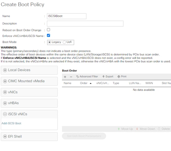
Step 2.4. The iSCSI vNIC is the name of the iSCSI vNIC that was created. Enter the same as shown in this image and click OK:

Step 3. The example in this step shows how to create one boot entry. A dual boot entry is possible with two vNICs. The iSCSI Target can still be the same. Because of Windows OS installation, there is a requirement that there must be a single boot entry or single path only at the time of installation. You have to return here and add after OS installation is done and MPIO is configured. This is covered in the section: MPIO.
Step 3.1. Select the Boot Policythat you just created and Expand iSCSI as shown in this image:
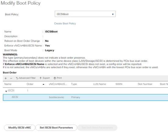
If you do not see Modify iSCSI vNIC, the iSCSI vNIC was not the one you created.
Step 3.2. Choose Set iSCSI Boot Parameters. In this example, no authentication is used.The Initiator Name Assignment is via an IQN-Pool. This IQN-Pool can be created if it is not there.The Initiator IP address Policy is an IP Pool where the UCS Initiator gets its IP address. It can be created if there is no IP Pool created yet as shown in this image:
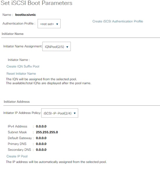
Of course, it is possible to assign IP addresses manually.
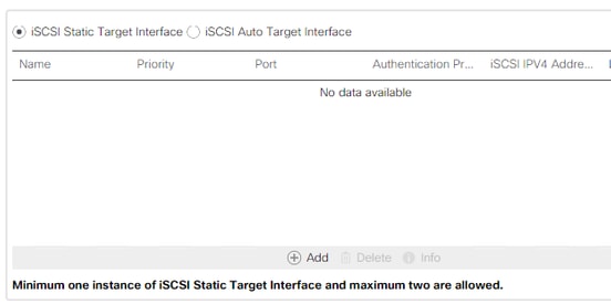
Step 3.3. Scroll down and choose iSCSI Static Target Interface and click Add as shown in this image:
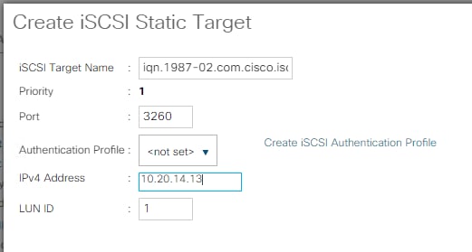
Step 3.4. The iSCSI Target Name is the HyperFlex iSCSI Target IQN documented at the time of the HyperFlex Target configuration.The IPv4 address is the HyperFlex iSCSI Cluster IP address.The LUN ID is the LUN ID that is documented at the time of the HyperFlex Target configuration as shown in this image:
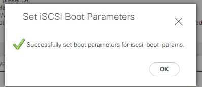
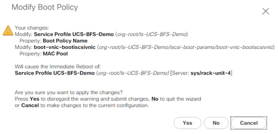
Step 3.5. Choose OK and Yes in order to modify the boot policy as shown in these images:
Step 4. Find Initiator IQN. The IQN of the UCS Initiator is not shown in the profile when this configuration is used. Navigate to SAN and choose the used IQN Pools as shown in this image:
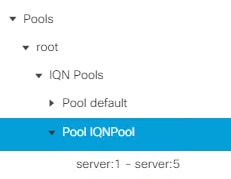
Step 4.1. Note down the IQN of the Profile as shown in this image:

This Initiator name must be configured in HyperFlex Initiator Group linked to the HyperFlex Target LUN where the server connects to the SAN Boot, as shown in this image:
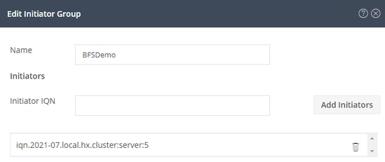
When you use a pool, the IQN name is not known in advance. If you create an IG with all the initiator IQNs, those Initiators can see all the same LUNs of the Target. This can be a situation that is not wanted.
Result:
SAN Boot from HyperFlex iSCSI LUN as shown in this image:

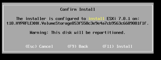
Install an OS on the Boot LUN if the LUN does not have any OS installed as shown in this image. The ESXi is installed on the LUN, and after installation, it boots from this LUN:
Troubleshoot iSCSI boot on UCS Manager CLI:
When there is a configuration error, you see Initialize Error 1 as shown in this image:

Different causes can give this error.UCS Manager CLI can get more information about the Initialize Error. SSH to the UCS-Manager and log in. In our example, server 4 has the service profile, and there is only an MLOM present. This gives the value of 4/1. Type the commands in the UCS Manager CLI as shown in this image:
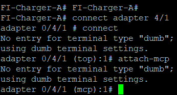
When you type help, you see a whole list of commands that are now possible. The commands for the iSCSI configuration are as shown in this image:

Problem 1: Ping Stats: In Progress
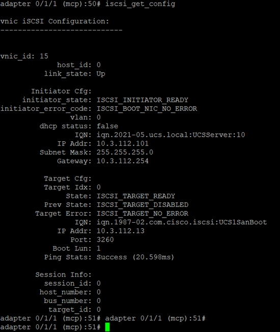
On the SSH session, type iscsi_get_configand check the output as shown in this image:
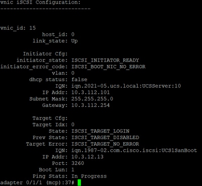
The Ping Stats is In Progress.This means the initiator cannot ping the HyperFlex iSCSI Cluster IP address. Verify the network path from the initiator to the HyperFlex iSCSI Target. In our example, the Initiator iSCSI IP address is outside the iSCSI Subnet configured on the HyperFlex Cluster. The Initiator IP address must be added to the HyperFlex iSCSI Allowlist.SSH to the HyperFlex Cluster IP address and enter the command:
hxcli iscsi allowlist add -p <Initiator IP address>In order to verify if the Initiator IP address is in the allowlist, use the command:
hxcli iscsi allowlist showProblem 2: Target Error: "ISCSI_TARGET_LOGIN_ERROR"
On the SSH session, type iscsi_get_configand check the output as shown in this image:
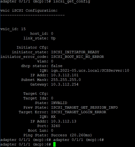
The Target Error is ISCSI_TARGET_LOGIN_ERROR. If authentication is used, verify the name and secrets. Ensure the Initiator IQN is in the HyperFlex Initiator Group and Linked to a Target.
Problem 3: Target Error: "ISCSI_TARGT_GET_HBT_ERROR"
On the SSH session, type iscsi_get_configand check the output as shown in this image:
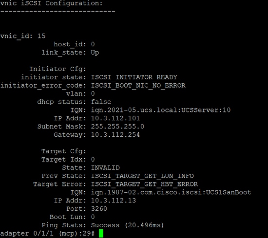
The Target Error is ISCSI_TARGET_GET_HBT_ERROR. In the configuration of the BOOT LUN, a wrong LUN ID was used. In this case, the BOOT LUN was set to 0, and it must have been assigned to1.
Working SAN Boot Configuration:
The SAN Boot From HyperFlex iSCSI must work when the iSCSI configuration is correct and you have the output as shown in this image:
Configure IMM
Prerequisites:
- Fabric Interconnects are claimed in Intersight
- Intersight Server Profile is already created and attached to a server
Network Diagram:
The physical network topology of the setup is as shown in this image:
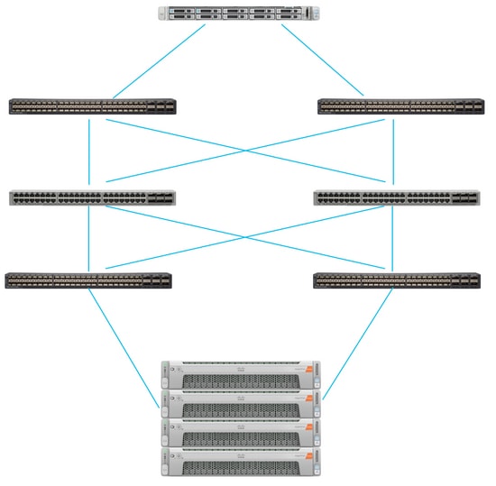
The UCS Server is in IMM and controlled via Intersight. The two Nexus switches have a VPC connection to the different pairs of Fabric Interconnect. Each HyperFlex node connects the network adapter to Fabric Interconnect A and B. A Layer 2 iSCSI VLAN network is configured without Layer 3 device delays for the SAN Boot.
Workflow:
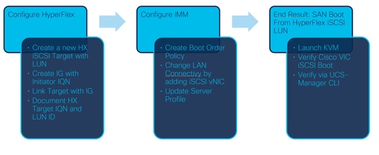
The steps to be followed in order to configure SAN Boot from HyperFlex iSCSI LUN are as shown in this image:
Step 1. In order to log in to Intersight, use https://intersight.com as shown in this image:
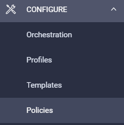
Step 2. Create a new Boot Order Policy. A new Boot Order policy is created for this server.Choose Configure > Policies as shown in this image:
Step 2.1. Click Create Policy at the right top corner as shown in this image:

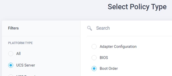
Step 2.2. On the left, choose UCS Server.Choose Boot Orderfrom the policies as shown in this image and click Start:
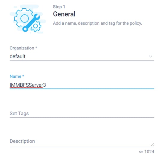
Step 2.3. In Step 1., give it a unique Name as shown in this image and click Next :
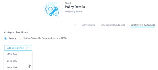
Step 2.4. In Step 2., choose UCS Server (FI-Attached). For this example, leave the Configured Boot Mode at Legacy. Expand the Add Boot Device and select iSCSI Boot as shown in this image:
Step 2.5. Give it a Device Name and an Interface Name as shown in this image:

The name of the Interface Name must be documented, and it is used in order to create a new vNIC. Click Create, a pop up must show on the screen as shown in this image:

Step 3. Change LAN Connectivity. A new LAN Connectivity can be created. In this example, the current LAN Connectivity of the Server Profile is edited.Search for the user policy at the Policies overview as shown in this image:

Step 3.1. Choose Edit Policy as shown in this image:

In this case, the Policy Name is IMMBFSLan. There is already a vNIC present in this configuration. Do not change anything in Step 1. as shown in this image and click Next:
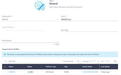
Step 3.2. In Step 2., choose Add vNIC as shown in this image:

Step 4. Change the Server Profile. The LAN Connectivity policy was updated, and the Boot Order must be changed in this Server Profile. Choose CONFIGURE > Profiles from the left bar in order to locate the UCS server profile, as shown in this image:

The UCS Profile can be selected directly from the UCS Server as shown in this image:

The Name must be used in the Boot Order policy. The server only has one network adapter, the MLOM. This must be configured in Slot ID.Leave the PCI Link at 0. The Switch ID for this example is A, and the PCI Order is the number of the latest vNIC which is 1. The Ethernet Network Control Policy, Ethernet QoS, and Ethernet Adapter can have default values. The best practice for iSCSI is to have an MTU of 9000, which can be configured in the Ethernet QoS Policy.
Step 4.1. Choose Ethernet Network Group Policy > Select Policyas shown in this image:
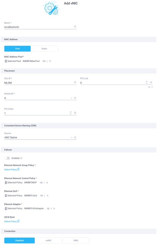
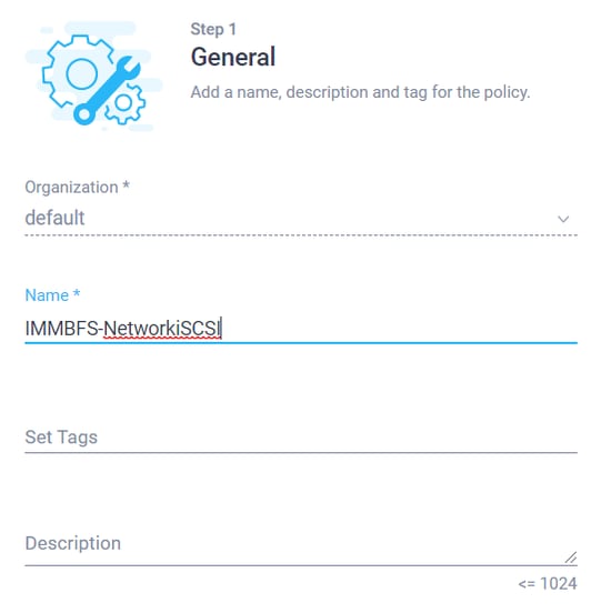
Use the Create New option. Give the Network Group Policy a Name as shown in this image and click Next :
Step 4.2. In Step 2., add the Allowed VLANs. In this case, it is just the iSCSI VLAN of the setup.Ensure at Native VLAN this iSCSI VLAN is added as shown in this image and click Create:
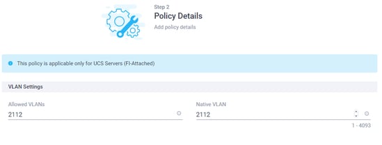
Only iSCSI Boot Traffic goes over this vNIC. The Native VLAN for iSCSI VLAN doesn’t have to be configured on the northbound switches.
Step 4.3. Choose the newly created Ether Network Group Policy as shown in this image:
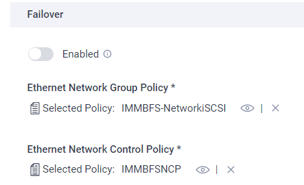
Step 5. ChooseSelect Policy at iSCSI Boot.Click Create New.
At Step 1., give the iSCSI boot a Name as shown in this image and click Next :
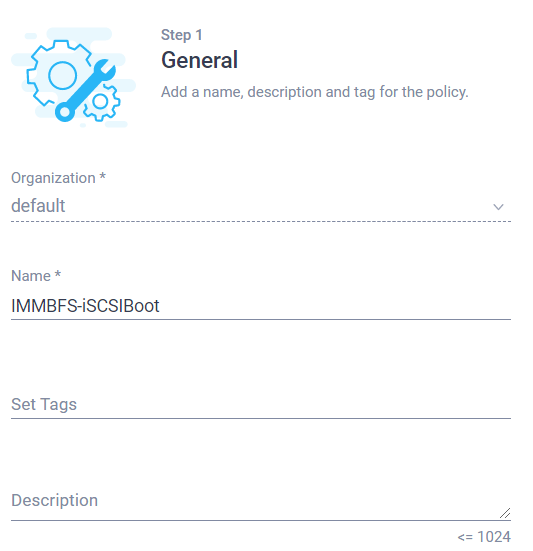
Step 5.1. In Step 2., choose Static as shown in this image:
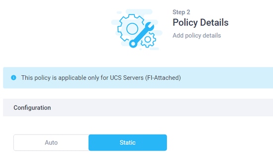
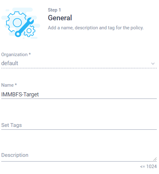
Click Select Policy of Primary Target. Choose to Create New.
In Step 1., give it a Name as shown in this image and do Next:
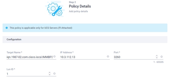
In Step 2., the Target Name is the HyperFlex iSCSI Target IQN documented when you configure HyperFlex. The IP address is the HyperFlex iSCSI Cluster IP address. Port is for iSCSI 3260. The Lun ID was documented at the time of the HyperFlex Target LUN Creation. In this case, it has a value of 1 as shown in this image, and choose to Create:
Step 5.2. At Step 2. of the iSCSI Boot, the Initiator IP Source can be a Pool. In this case, an IP pool is created. The initiator gets an IP address out of this pool in order to connect to the HyperFlex iSCSI Cluster IP address as shown in this image:
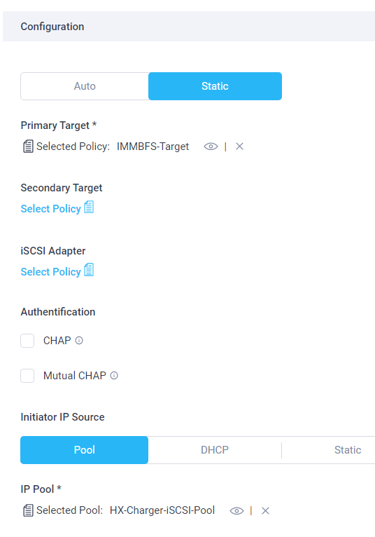
Click Create. Verify that the correct policies are selected. Choose Add. A new vNIC is created for the iSCSI Boot Traffic as shown in this image:

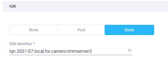
Step 5.3. The initiator needs an IQN which can be assigned via a pool or Manual. For this example, Manual is chosen, and the value of the IQN is already at the correct Initiator Group of HyperFlex as shown in this image:
Click Update. A warning is shown, select Save, and there comes a pop-up at the right top corner as shown in this image:

Step 6. Change the Server Profile. Find the correct Server Profile from UCS Server Profiles as shown in this image:

Step 6.1. Edit Policy from the three dots option on the right side and click Edit as shown in this image:
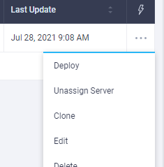
At Step 1. of the policy, leave it as-is, as shown in this image, and hit Next:
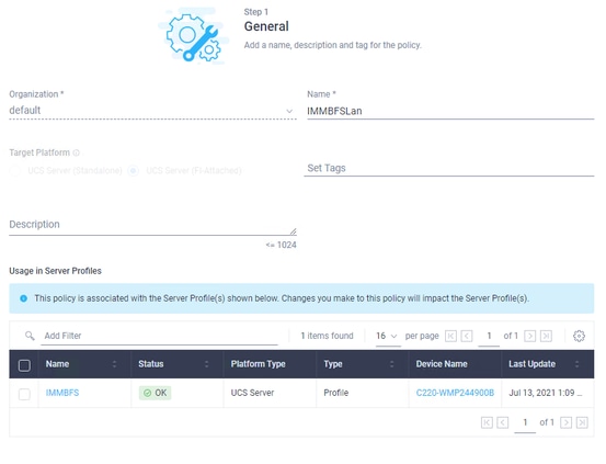
In Step 2., click Next.
In Step 3., click the current Boot Order Policy as shown in this image:

Choose the newly created Boot Order Policy as shown in this image and hit Next:
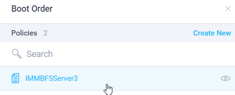
Leave all the other policies in Step 3. as is and hit Next.
Make no changes in Step 4. as shown in this image and hit Next:
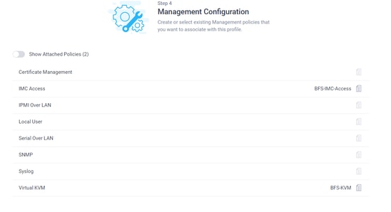
Leave the policies in Step 5. as is as shown in this image and hit Next:

The LAN Connectivity Policy is already changed and hitNext.
In Step 7., you can review the configuration and click Deploy as shown in these images:
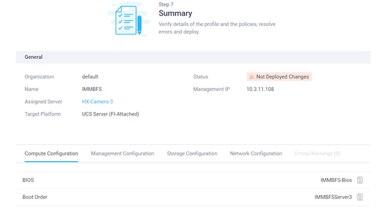
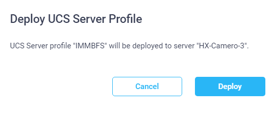
There is a green pop-up at the right top corner as shown in this image:

The policy goes in a Validating Status and after a couple of seconds, it is ready as shown in these images:


Verify:
Navigate to your server on Intersight and use the three dots option on the right and click Launch vKVM as shown in these images:

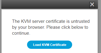


When the Cisco VIC iSCSI Boot Driver is loaded, and the HyperFlex iSCSI Target is discovered, the output of the screen looks like as shown in this image:

When there is a misconfiguration on the HyperFlex or IMM side, you can see an Initialize Error 1 as shown in this image:

Boot from HyperFlex iSCSI Target with MPIO
An initiator can consist of multiple physical interfaces. In this case, it is possible to have those connections still point to the HyperFlex Target, and in case of a failure, the OS can choose the other path for the iSCSI connection. If you configure Windows and ESXi with MPIO, a second iSCSI vNIC must be created in the UCS-Manager, CIMC, or Intersight, which depends on the configuration you use. The procedure is the same as the first iSCSI vNIC you made. The creation of the second iSCSI vNIC is not part of this document. The HyperFlex iSCSI Target must be configured for CHAP authentication or disable the initiator CHAP authentication.
Windows OS Installation on iSCSI Boot LUN
Prerequisites:
- Microsoft Windows OS installation CD or ISO image in .iso format
- UCS driver ISO for Cisco VIC cards: Driver ISO
- Please download the driver version that matches the supported UCS infrastructure bundle version.
- The Cisco VIC driver is not inside Windows installation ISO image/CD, so users need to load the driver at the time of OS installation.
Workflow:
Windows OS installation:
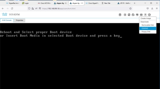
Step 1. Open UCS KVM console in order to map Microsoft Windows OS installation ISO image and boot the server to the image as shown in this image:
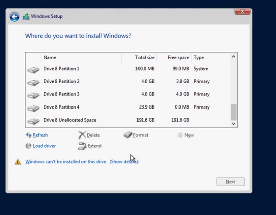
Step 2. In the Windows installation environment WinPE, follow the onscreen instruction until the 'Where do you want to install Windows?' screen. HX iSCSI LUN does not show up yet and needs to load the VIC driver. Click Load driver as shown in this image:
Step 3. From the UCS KVM menu, unmap the Windows OS installation CD/ISO and map the UCS driver ISO as shown in this image:
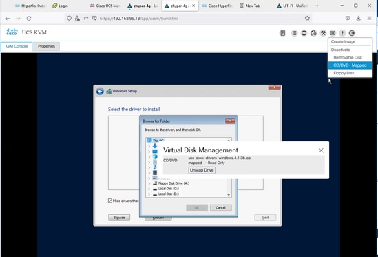
Step 4. Browse the CD drive and look for the Cisco VIC network driver for your OS version, based on your VIC model. Click OK as shown in this image:
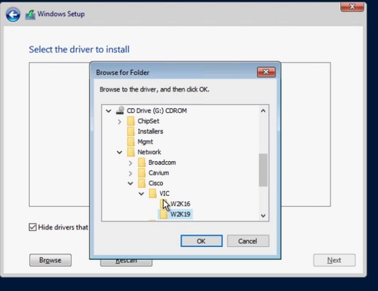
An incorrect driver could result in an inaccessible boot disk error after a reboot if chosen for the wrong VIC model
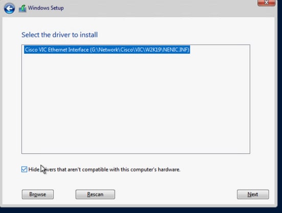
Step 5. The support driver file shows up in the list, choose it and click Next as shown in this image. After that, it takes you back to the 'Where do you want to install Windows?' screen:
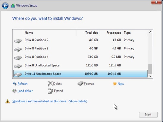
Step 6. At this point, HX iSCSI LUN must show up. But there is a warning message about cannot install. From the KVM console, unmap the driver ISO image and remap the Windows installation image. Click Refresh. The warning message disappears, and you can click Next as shown in this image:
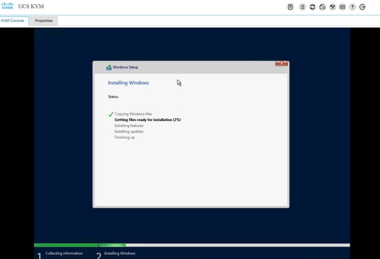
Step 7. Windows installation must be started and completed successfully as shown in this image:
Post OS install configuration:
Configure network and ChipSet driver installation:
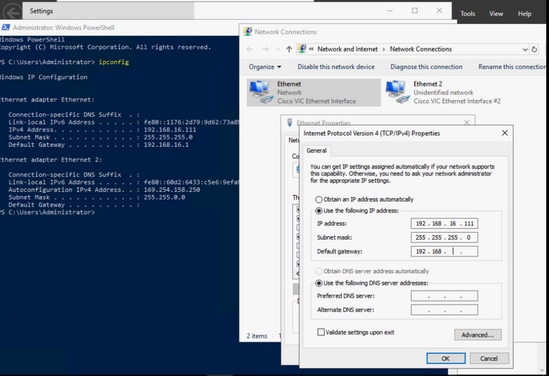
Step 1. In Windows ipconfig output, the iSCSI NIC can already show the IP address received from iBFT at the time of boot up, but the user still needs to configure the same IP manually in the network connection as shown in this image:
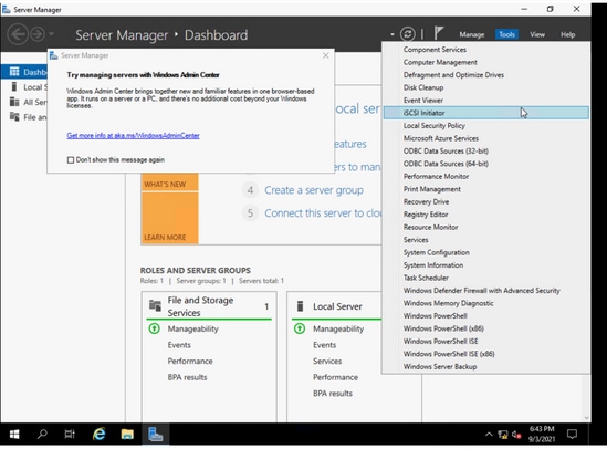
Step 2. Start the iSCSI initiator service from Windows > Server Manager > Tools > iSCSI Initiatoras shown in this image:
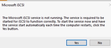
Step 3. In the pop-up message in order to start the iSCSI service automatically after reboot, choose Yes as shown in this image:
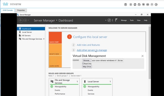
Step 4. Some devices under Computer Management show yellow question marks due to lack of driver, so youneed to install the chipset driver. Map the Windows driver ISO image again via UCS KVM as shown in this image:
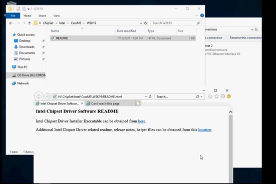
Step 5. Browse the CD ROM, navigate to ChipSet\<your server CPU>\<your server model>\<your Windows OS version>, open the README file. Click location link, Open SetupChipSet.exe as shown in this image. Then follow the wizard in order to install the chipset driver. Restart the server when installation is finished:
Configure Multipathing MPIO:
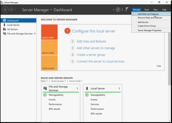
Step 1. Navigate toWindows > Server Manager > Add Roles and Feature as shown in this image:
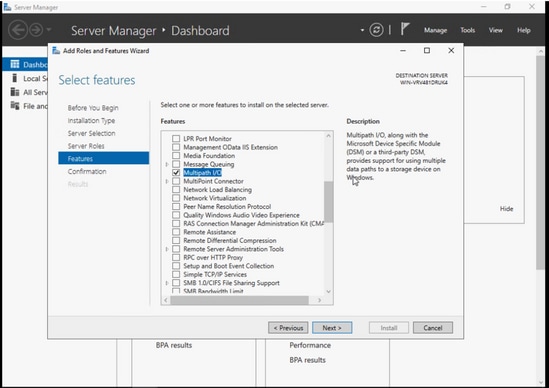
Step 2. Navigate to the Features tab and choose Multipath I/O, hit Next, and install and restart the host when finished as shown in this image:
Let the OS restart, log back into the Windows, and verify that the MPIO installation is completed.
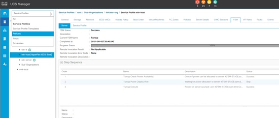
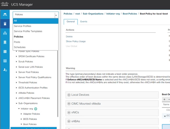
Step 3. Add the second path in the boot order. Navigate to the UCS manager. Choose Policies from the top-left drop-down list as shown in this image:
Step 3.1. Look for Boot Policies under the organization tree that the service profile is created. It can be under sub-organization at the bottom if it is not under the organization. Then look for the boot policy that you named in the previous step as shown in this image:
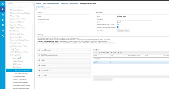
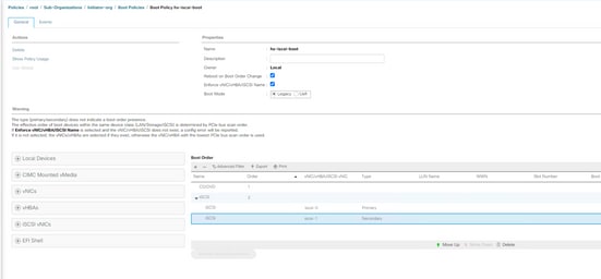
Step 3.2. From the left panel under iSCSI vNICs, double click the Add iSCSI Boot, then the pop window shows up and enter the iSCSI vNIC name that you entered in the previous step. The second iSCSI vNIC must show up in the correct boot order as shown in this image. Hit Save Changes:
Step 3.3. From the left top drop-down box, choose All and choose the service profile as shown in this image:
Step 3.4. Navigate to the Boot Order tab, choose the second iSCSI entry and click the Set iSCSI boot Parameters as shown in this image:
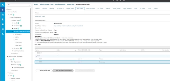
Step 3.5. Enter the second IP address as shown in this image:
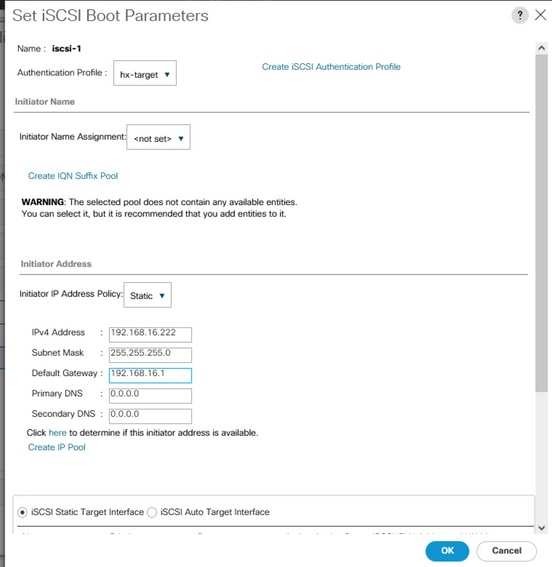
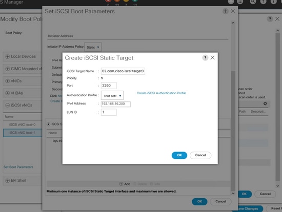
Scroll down, click Add again and enter the same target info as shown in this image:
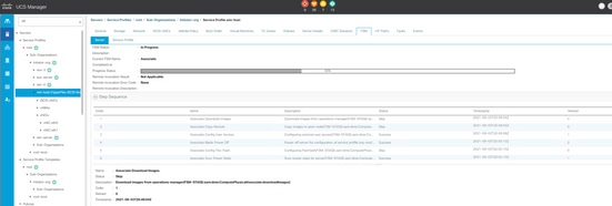
Step 3.6. UCS server reboots (if it does not reboot by itself and waits for a graceful reboot, you need to reboot the host manually). UCS PNUOS reconfigures the boot order with a second iSCSI vNIC. You can check the status in the FSM tab, and wait for it to finish as shown in this image:
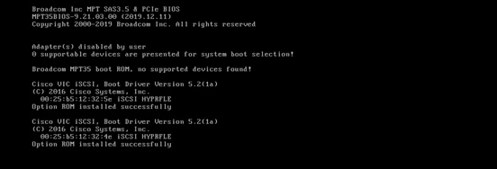
Step 3.7. The second path must show up in iBFT (in POST) when the server boots up as shown in this image:
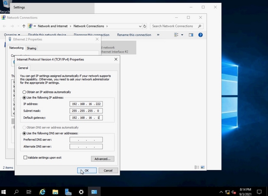
Step 4. The second NIC IP address needs to be entered manually in order to make it static. In Windows, add the IP address for the second NIC under Ethernet properties, and hit OK as shown in this image:
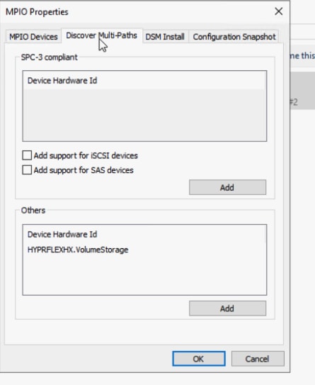
Step 4.1. Open MPIO App, navigate to the Discover Multi-Paths tab, and from the Others area, click and add HYPRFLEXHX.VolumeStorage as shown in this image:
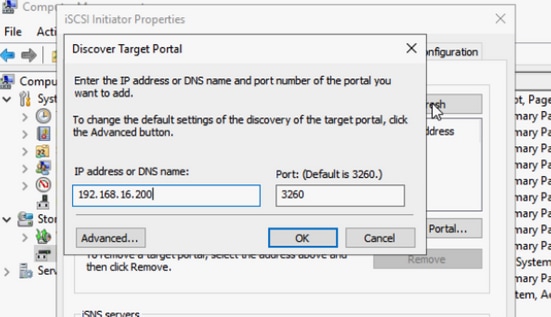
Step 4.2. Reboot the server.Open the iSCSI Initiator app > Discovery > Discover Portal as shown in this image:
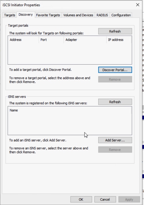
Step 4.3. Enter target IP address and hit OK as shown in this image:
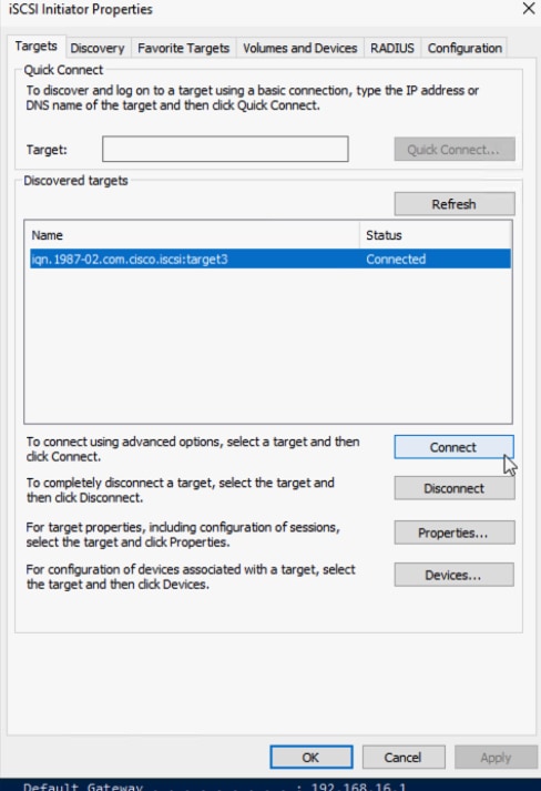
Step 4.4. Navigate to Targets > Connect as shown in this image:
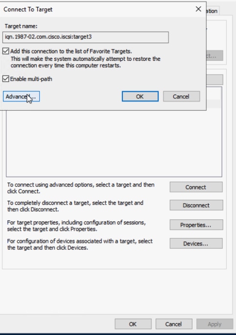
Step 4.5. Check Enable multi-path and choose the Advanced option as shown in this image:
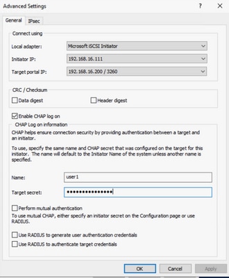
Local adapter: Microsoft iSCSI Initiator
Initiator IP: Choose the first NIC IP
Target Port IP: Choose target IP
Check Enable CHAP log on. Enter the CHAP info from the target.Click OK two times as shown in this image:
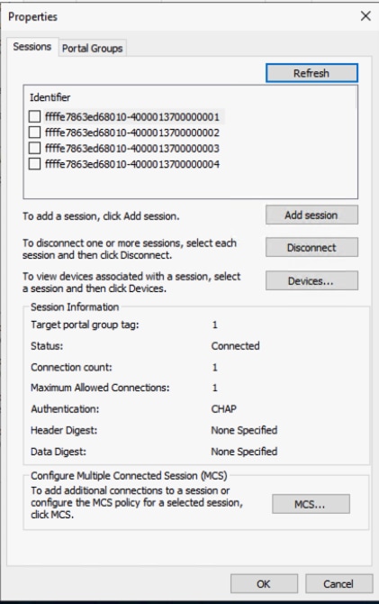
Step 4.6. Choose the Connect option again and repeat the steps for the second Initiator IP. After that, click Connect, and there are multiple sessions now as shown in this image:
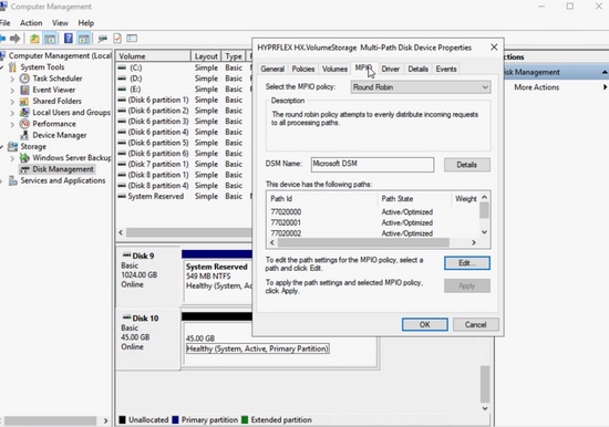
Step 4.7. After the reboot, navigate to Computer Management > Disk Management, right-click the C: drive. The MPIO tab must show up by now, and if you click it, there must be multiple paths as shown in this image:
Troubleshoot:
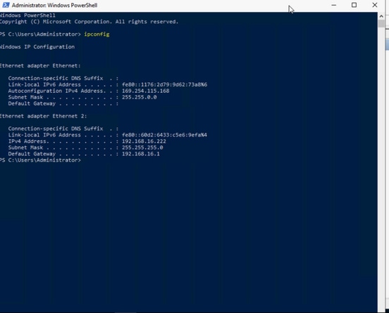
On rare occasions, after some reboot or path recovery, the static IP address can be reset to the default random IP address. Please check it with ipconfig and ensure the static IP address you entered still exists as shown in this image:
Esxi OS Installation on iSCSI Boot LUN
Prerequisites:
- There must be additional vNIC created in UCS service profile ESXi management traffic.
- For multi-path configuration, you can add the second path in UCS boot order before or after the OS installation, but it is recommended to add it before for ESXi install. Same steps in windows as shown in the image add the second path in the boot order.
- The Cisco VIC driver is not inside regular ESXi OS installation ISO image/CD, so you need to download the custom Cisco ESXi image from the VMware website. Look for the ESXi Cisco Custom image for the ESXi version desired - Custom_iso.
- The latest UCS driver ISO can be downloaded from this location - Driver_iso.Please use the driver version that matches the UCS infrastructure bundle version.
Workflow:
Esxi OS installation:
Step 1. Open UCS KVM of the service profile, map the Cisco Custom ESX ISO as shown in this image:

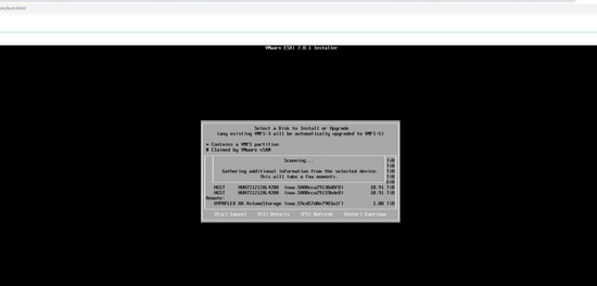
Step 2. Boot to the image, follow the onscreen instruction in order to install ESX. At the 'Select a Disk to Install or Upgrade' screen, scroll down to Remote and look for HYPERFLEX HX.VolumeStorage LUN. Choose it and click Enteras shown in this image:
Step 3. Follow the onscreen instructions in order to complete the rest of the installation.
Post OS install configuration:
Step 1. Management NIC configuration. After OS install, match MAC addresses to identify dedicated management NICs from UCS vNIC and configure a management IP address and VLAN as shown in this image:
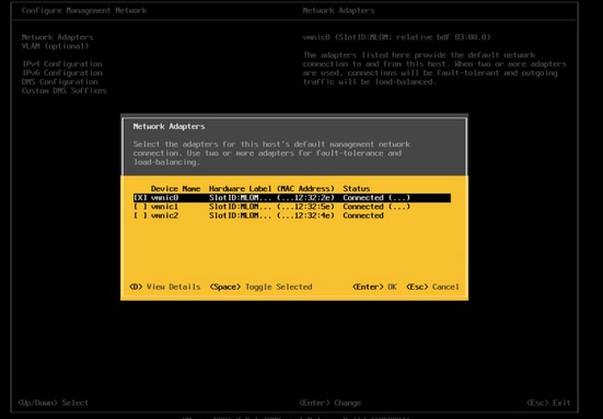
When you use the IP address, open the vSphere client in the web browser or add it to vCenter. You can configure with either vSphere or vCenter, but the vSphere web client is used as an example in this document.
Step 2. Configure the iSCSI network. After you log into the vSphere web client, choose Networking > Physical NICs. Observe the mac address to NIC name that matches as shown in this image:

Step 2.1. Navigate to the Virtual switches tab. Click the iSCSIBootvSwitch as shown in this image:
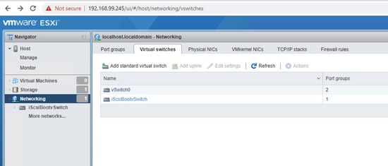
Step 2.2. There is a warning about no uplink redundancy. Choose Actions > Add uplink as shown in this image:
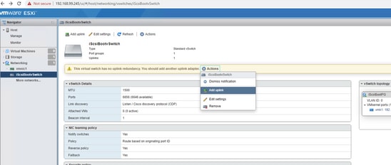
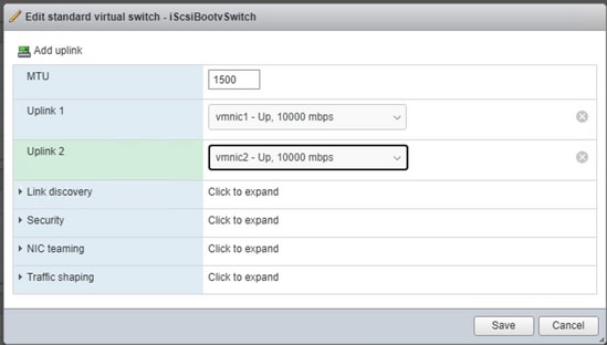
Step 2.3. Select the second iSCSI NIC for the uplink two and click Save. A second physical adapter shows up in the iSCSIBootvSwitch. If you need to modify the MTU size, you can change it here as shown in this image:
Step 2.4. Choose Networking > VMkernel NICs > Add VMKernel NIC, enter the details and Create, as shown in this image:
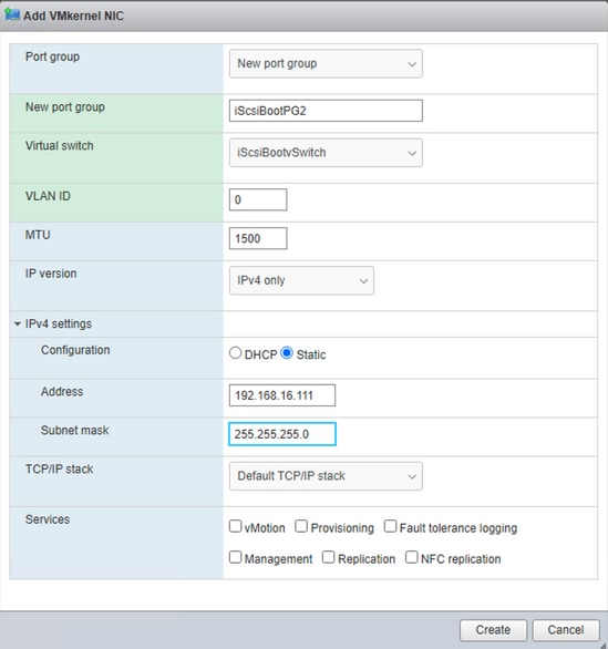
In the Add VMKernel NIC screen:
- Port group: New port group
- New port group: enter iSCSIBootPG2
- Virtual switch: choose iSCSIbootvSwitch from the drop-down list
- VLAN ID: must be 0 for native traffic
- MTU: choose the appropriate MTU that you have chosen
- IPv4 settings: choose static and expand it. Enter the same IP address of other iSCSI NIC that was entered in the UCS boot order
Multipathing Configuration Using VMkernel NIC Based Port Binding:
GUI method:
Step 1. There must be two iSCSI port groups now. Choose the iSCSIBootPG as shown in this image:

Step 2. Click the yellow pencil edit icon next to iSCSIBootPG as shown in this image:

Step 3. In the Edit port group screen, expand NIC teaming as shown in this image:
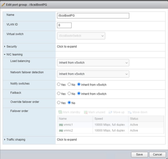
Step 4. Choose the Override failover order radio button, choose the recently added second iSCSI NIC vmnic2, and choose Mark unused. Click Save as shown in this image:
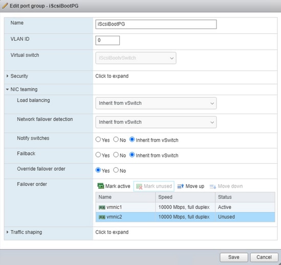
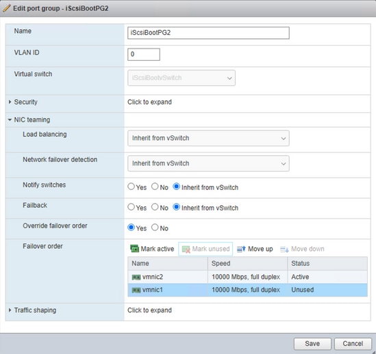
Step 5. Repeat Step 4. on the iScsiBootPG2 but make vmnic1 as Mark Unused as shown in this image:
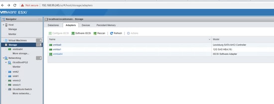
Step 6. Navigate to Storage > Adapters > Software iSCSI as shown in this image:
Step 7. On the Configure iSCSI screen, CHAP authentication, Use CHAP and enter the same CHAP credential from HX storage as shown in this image:
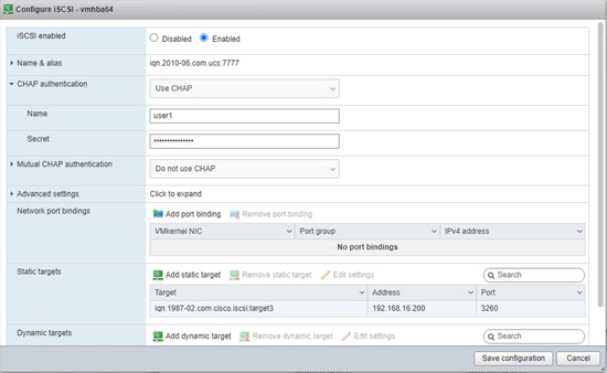
Any typo here can make the OS unbootable next time, so please double-check.
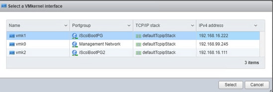
Step 8. In the Network port bindings area on the same screen, choose to Add port binding >iScsiBootPG and repeat the step for iScsiBootPG2 and Save Configuration as shown in this image:
CLI method:
- List physical NIC: esxcli network nic list
- List current vSwitch: esxcfg-vswitch -l
- Add second uplink to the vswtich: esxcfg-vswitch -L vmnic2 iScsiBootvSwitch
- Add the second port group: esxcfg-vswitch -A iScsiBootPG2 iScsiBootvSwitch
- Map each VMkernel port in order to use only one active adapter and in order to move the second network adapter to the unused adapter list: esxcfg-vswitch -N vmnic1 -p iScsiBootPG iScsiBootvSwitch
- Map each VMkernel port in order to use only one active adapter and in order to move the second network adapter to the unused adapter list: esxcfg-vswitch -N vmnic2 -p iScsiBootPG2 iScsiBootvSwitch
- Assign an IP address to the second port group: esxcfg-vmknic -a -i 192.168.16.111 -n 255.255.255.0 iScsiBootPG2
- For port binding, look for vmk number with esxcfg-vmknic -l
- Configure portbinding in order to enable multipathing:
esxcli iscsi networkportal add --nic vmk1 --adapter vmhba64
esxcli iscsi network portal add --nic vmk2 --adapter vmhba64
- Check iSCSI adapter: esxcli iscsi adapter list
- Optional - Check whether CHAP is already set: esxcli iscsi adapter auth chap get -A vmhba64
- Optional - If unidirectional CHAP is not set, configure with the same info from UCS Boot Order: esxcli iscsi adapter auth chap set --direction=uni --chap_username=<name> --chap_password=<pwd> --level=[prohibited, discouraged, preferred, required] --secret=<string> --adapter=<vmhba>
-
Rescan and rediscover the storage with new changes:
esxcli iscsi adapter discovery rediscover
esxcli storage core adapter rescan --adapter=vmhba64
- In order to see all CLI change in the UI, restart the UI services for host and vCenter:
/etc/init.d/hostd restart && /etc/init.d/vpxa restart
Multipathing Policy:
The default multipathing policies are fixed, but Cisco recommends multipathing policies as Round Robin. Multipathing can only be changed through ESX CLI or vCenter server. Please follow the steps from this VMware KB: multipathing_policies.
Look for naa string for iSCSI storage with this command:
esxcfg-mpath -L
Set the round-robin policy with this command:
esxcli storage nmp device set --device naa.59cd57d0e7903a1f --psp VMW_PSP_RR
Verify multipath configuratioin with this command:
esxcfg-mpath -bd naa.59cd57d0e7903a1f
Troubleshoot:
In a multi-path failover/failback scenario, when the original path is recovered, the iSCSI storage adapter in vSphere needs to be rescanned manually in order to see the recovered path as shown in this image:

CLI command: esxcli storage core adapter rescan --adapter=vmhba64
Revision History
| Revision | Publish Date | Comments |
|---|---|---|
1.0 |
08-Mar-2022 |
Initial Release |
Contributed by Cisco Engineers
- Joost van der MadeCisco TAC Engineer
- Zayar SoeCisco TAC Engineer
Contact Cisco
- Open a Support Case

- (Requires a Cisco Service Contract)
 Feedback