Introduction
This document describes how to implement a Disjoint Layer 2 (DL2) configuration on a HX Cluster from the UCS Manager (UCSM) and ESXi perspectives.
Prerequisites
Requirements
Cisco recommends that you have knowledge of these topics:
- Basic understanding of the DL2 configuration
- Basic knowledge of Hyperflex Cluster
- Recommended UCSM knowledge on vNICs, Service Profiles, and templates
Other requirements are:
- At least one available link on each Fabric Interconnect and two available links on your upstream switch.
- The links between the Fabric Interconnects and the upstream switch must be up, they must be configured as uplinks. If they are not, check this System Configuration - Configuring Ports to configure them on UCSM.
- The VLANs to be used must be created on UCSM already. If they are not, do these steps Network Configuration - Configuring Named VLAN.
- The VLANs to be used must be created on the upstream switch already.
- The VLANs to be used cannot exist on any other virtual NIC (vNIC) on the Service Profiles.
Components Used
This document is not restricted to specific software and hardware versions.
- 2x UCS-FI-6248UP
- 2x N5K-C5548UP
- UCSM version 4.2(1f)
The information in this document was created from the devices in a specific lab environment. All of the devices used in this document started with a cleared (default) configuration. If your network is live, ensure that you understand the potential impact of any command.
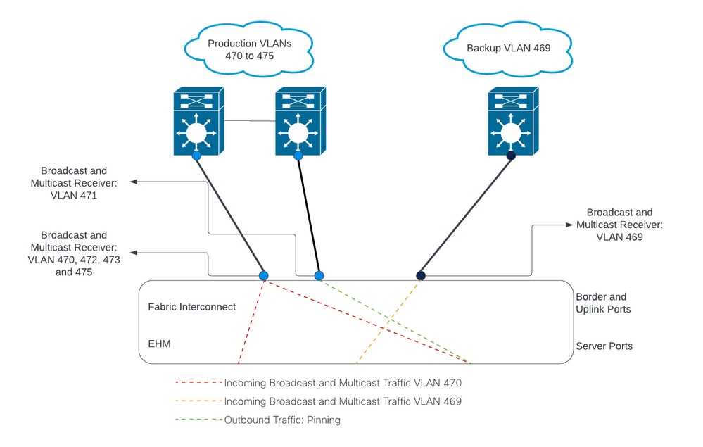
Network Diagram
Configurations
DL2 configurations are used to segregate traffic on specific uplinks to the upstream devices, so the VLAN traffic does not mix.
Configure the new vNICs
Step 1. Log in to UCSM, and click on the LAN tab on the left panel.
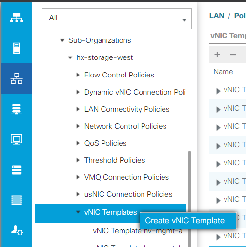
Navigate to Policies > root > Sub-organizations > Sub-organization name > vNIC templates. Right-click it and click Create vNIC Template.
Step 2. Name the template, leave Fabric A selected, scroll down, and select the appropriate VLANs for the new link. The remaining settings can be configured as desired.
Next, repeat the same process, but select Fabric B this time.
Step 3. From the LAN tab, navigate to Policies > root > Sub-organizations > Sub-organization name > LAN Connectivity Policies > Hyperflex.
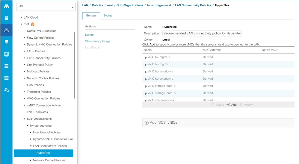
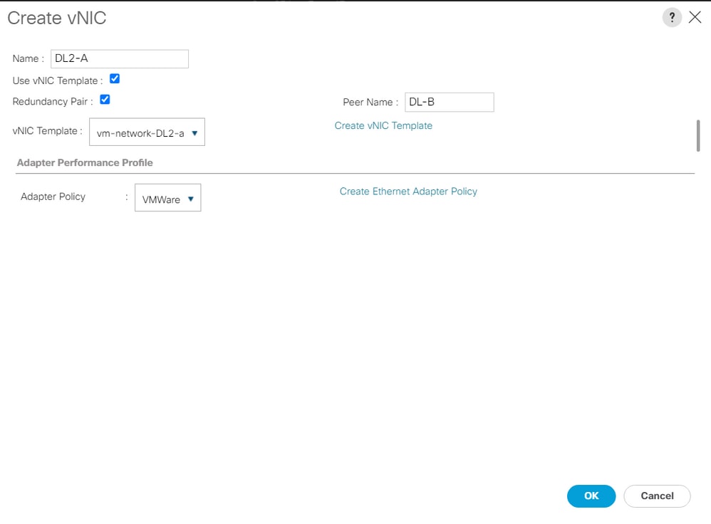
Step 4. Click Add, name the vNIC, and select a MAC pool from the dropdown menu.
Check the Use vNIC Template and the Redundancy Pair boxes. From the vNIC Template dropdown, select the new template, and next to it, enter the Peer Name.
Select the desired Adapter Policy and click OK.
Step 5. On the vNIC list, look for the Peer of the one just created, select it, and click Modify.
Click the Use vNIC Template box and select the other template that was created from the dropdown.
Click Save Changes at the bottom, this triggers Pending Activities for the related servers.
Acknowledge Pending Activities
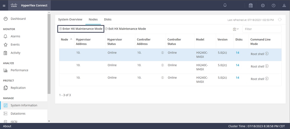
Step 1. Log in to HX Connect, navigate to System Information > Nodes, click one of the nodes, and then click Enter HX Maintenance Mode, then wait for the task to finish.
Step 2. From vCenter, ensure the node is in maintenance.
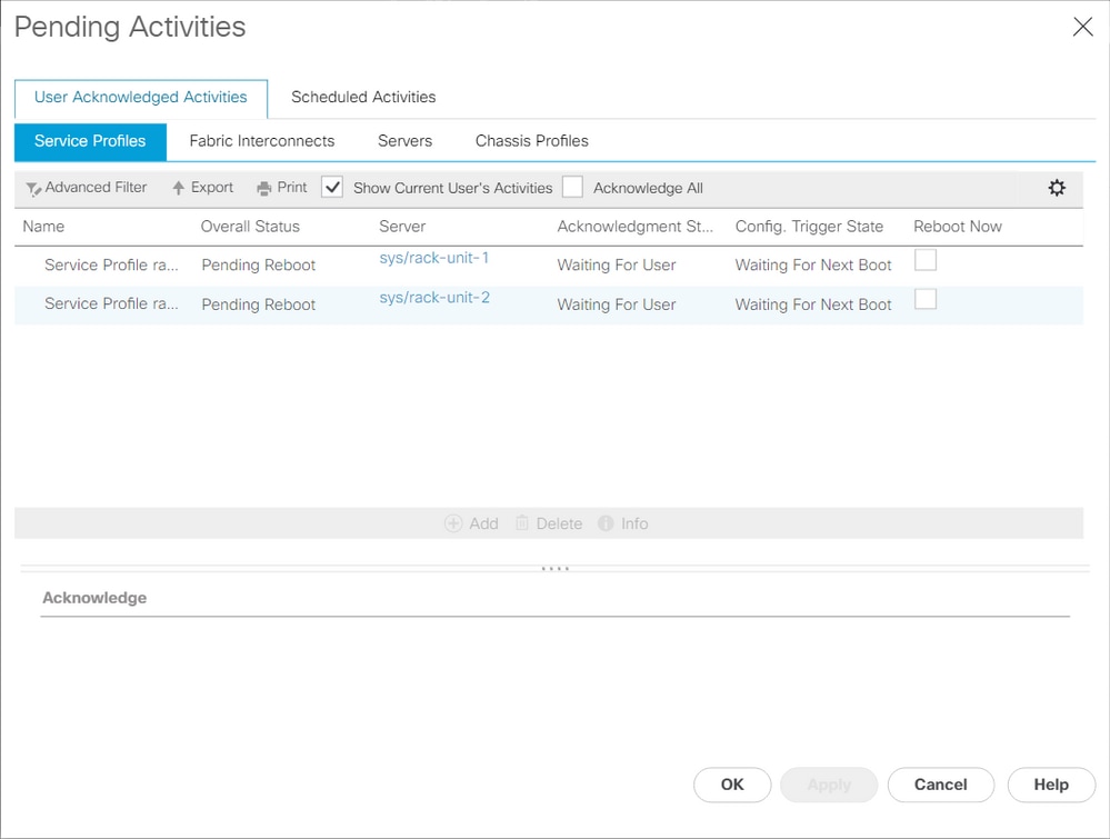
Step 3. Once the node is in maintenance, go back to UCSM, click the bell icon at the top right corner, and under Reboot Now.
Check the box that matches the server that is currently in maintenance, then click OK.
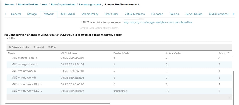
Step 4. After the server boots up, ensure the new vNICs are present by navigating to Servers > Service Profiles > root > Sub-Organizations > Sub-organization name > Service Profile name.
Click Network, scroll down and the new vNICs must be there.
Step 5. Take the server out of the maintenance mode from the HX Connect UI.
Click Exit HX Maintenance Mode.
When the server gets out of maintenance, the Storage Controller Virtual Machine (SCVM) boots up and the cluster starts the healing process.
In order to monitor the healing process, SSH into the Hyperflex (HX) Cluster Manager IP and run the command:
sysmtool --ns cluster --cmd healthdetail
Cluster Health Detail:
---------------------:
State: ONLINE
HealthState: HEALTHY
Policy Compliance: COMPLIANT
Creation Time: Tue May 30 04:48:45 2023
Uptime: 7 weeks, 1 days, 15 hours, 50 mins, 17 secs
Cluster Resiliency Detail:
-------------------------:
Health State Reason: Storage cluster is healthy.
# of nodes failure tolerable for cluster to be fully available: 1
# of node failures before cluster goes into readonly: NA
# of node failures before cluster goes to be crticial and partially available: 3
# of node failures before cluster goes to enospace warn trying to move the existing data: NA
# of persistent devices failures tolerable for cluster to be fully available: 2
# of persistent devices failures before cluster goes into readonly: NA
# of persistent devices failures before cluster goes to be critical and partially available: 3
# of caching devices failures tolerable for cluster to be fully available: 2
# of caching failures before cluster goes into readonly: NA
# of caching failures before cluster goes to be critical and partially available: 3
Current ensemble size: 3
Minimum data copies available for some user data: 3
Minimum cache copies remaining: 3
Minimum metadata copies available for cluster metadata: 3
Current healing status:
Time remaining before current healing operation finishes:
# of unavailable nodes: 0
Step 6. Once the cluster is healthy, repeat steps 1-6. Do NOT proceed with the next step until all servers have the new vNICs present.
Configure the VLANs
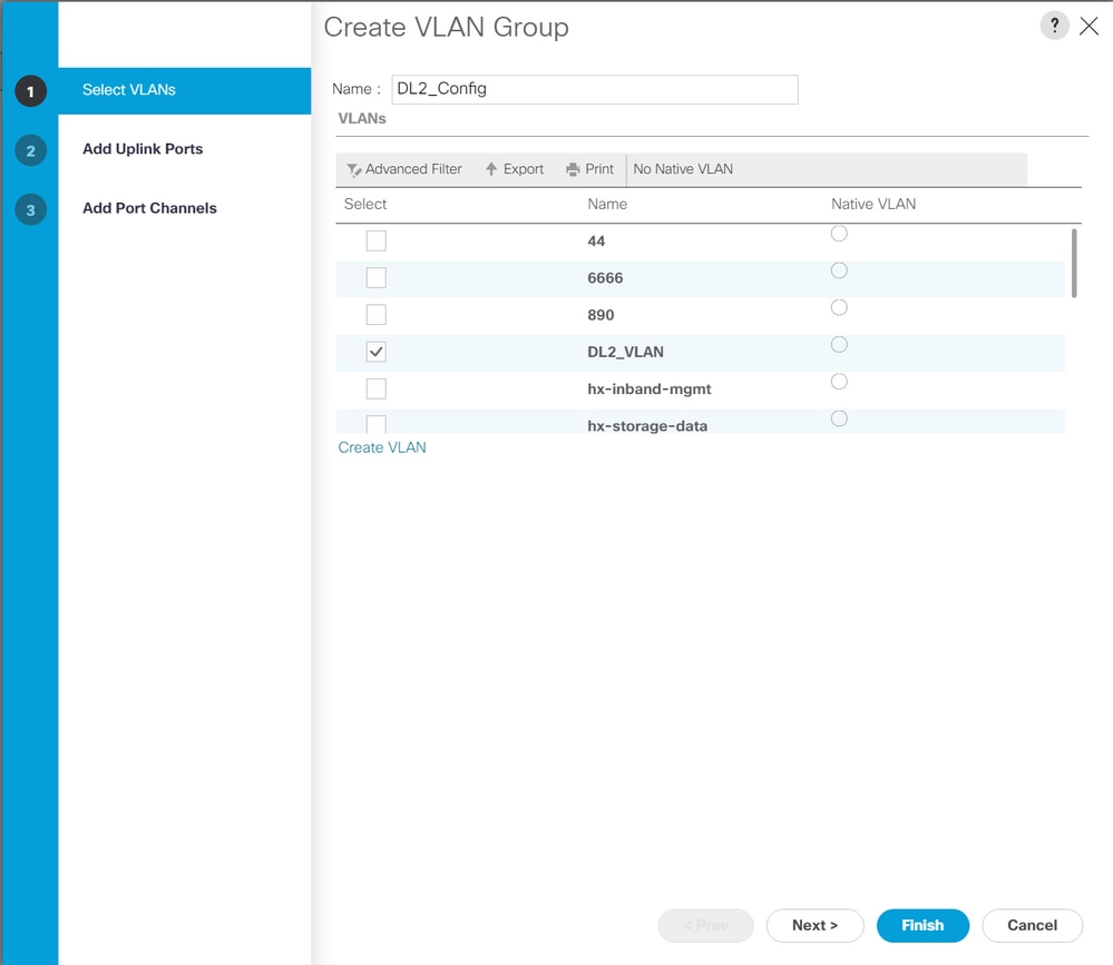
Step 1. From UCSM, navigate to LAN > VLANs > VLAN Groups and click Add.
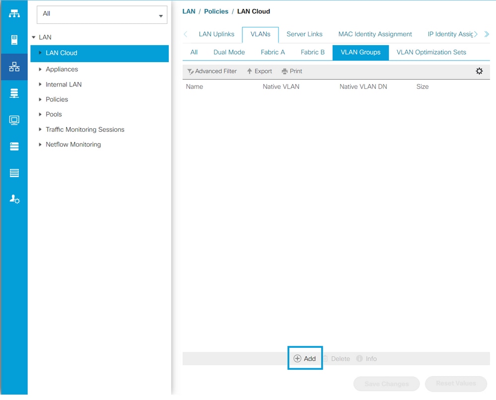
Step 2. Name the VLAN Group and select the appropriate VLANs below, click Next, and move to step 2 of the wizard to add single Uplinks Ports or to step 3 to add Port Channels.
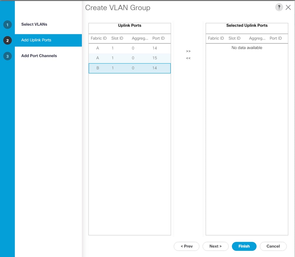
Step 3. Add the Uplink Port or Port Channel by clicking them and clicking the >> icon. Click Finish at the bottom.
ESXi configuration
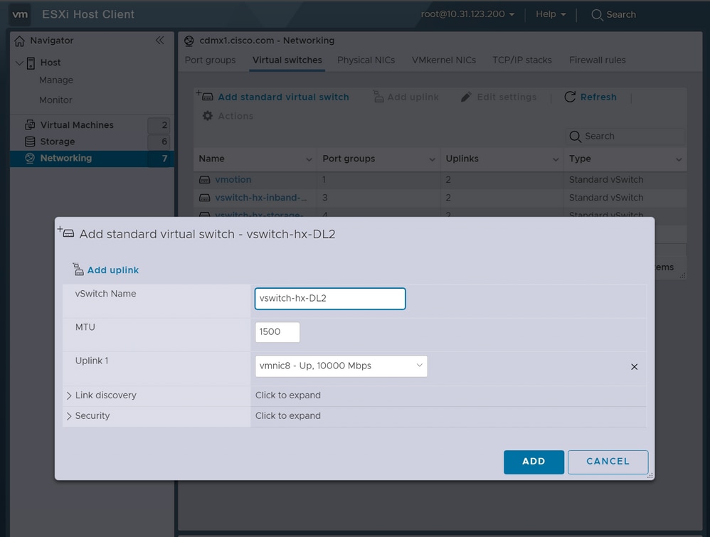
Step 1. Log in to the vSphere of the ESXi host, navigate to Networking > Virtual Switches, and click Add standard virtual switch.
Step 2. Name the vSwitch and one of the new vmnics is there already, click Add uplink to add the 2nd one. Click Add.
Step 3. Navigate to Networking > Port groups and click Add port group
Step 4. Name the port group, enter the desired VLAN, and select the new Virtual switch from the dropdown.
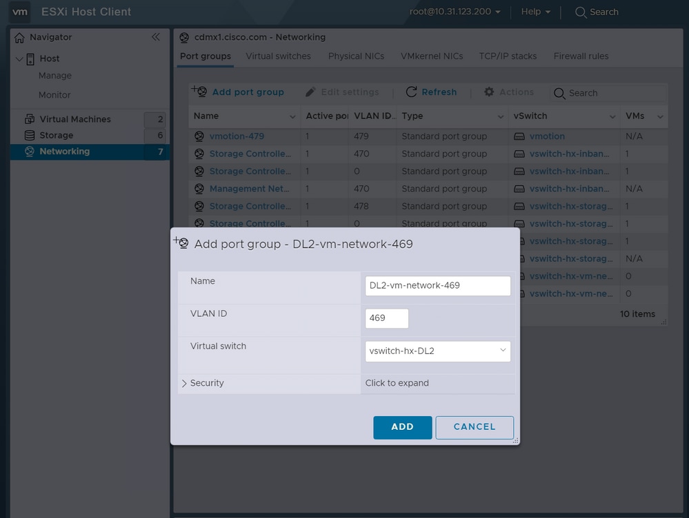
Step 5. Repeat step 4 for each VLAN flowing through the new links.
Step 6. Repeat steps 1-5 for each server that is part of the cluster.
Verify
UCSM Verification
Navigate to Equipment > Rack-Mounts > Servers > Server # > VIF Paths and expand Path A or B, under the vNIC column, look for the one that matches the DL2 vNIC and that Virtual Circuit must be pinned to the Fabric Interconnect (FI) Uplink or Port Channel that was recently configured.

CLI Verification
Virtual Interface (VIF) Path
On an SSH session to the Fabric Interconnects, run the command:
show service-profile circuit server <server-number>
This command displays the VIF Paths, their corresponding vNICs, and the interface they are pinned to.
    Fabric ID: A
        Path ID: 1
        VIF        vNIC            Link State  Oper State Prot State    Prot Role   Admin Pin  Oper Pin   Transport
        ---------- --------------- ----------- ---------- ------------- ----------- ---------- ---------- ---------
               966 hv-mgmt-a       Up          Active     No Protection Unprotected 0/0/0      0/0/1      Ether
               967 storage-data-a  Up          Active     No Protection Unprotected 0/0/0      0/0/1      Ether
               968 vm-network-a    Up          Active     No Protection Unprotected 0/0/0      0/0/1      Ether
               969 hv-vmotion-a    Up          Active     No Protection Unprotected 0/0/0      0/0/1      Ether
               990 network-DL2-a   Up          Active     No Protection Unprotected 0/0/0      1/0/14     Ether
The Oper Pin column must display the recently configured FI Uplink or Port Channel under the same line as the DL2 vNIC.
On this output, the VIF 990, which corresponds to the vm-network-DL2-b vNIC, is pinned to interface 1/0/14.
Pinning in the Uplinks
Fabric-Interconnect-A# connect nx-os a
Fabric-Interconnect-A(nxos)# show pinning border-interfaces
--------------------+---------+----------------------------------------
Border Interface     Status    SIFs
--------------------+---------+----------------------------------------
Eth1/14              Active    sup-eth2 Veth990 Veth992 Veth994
On this output, the Veth number must match the VIF number seen on the previous output and be on the same line as the correct uplink interface.
Designated Receiver:
Fabric-Interconnect-A# connect nx-os a
Fabric-Interconnect-A(nxos)# show platform software enm internal info vlandb id <VLAN-ID>
vlan_id 469
-------------
Designated receiver: Eth1/14
Membership:
Eth1/14
On this output, the correct uplink must be displayed.
Upstream Switches
On an SSH session to the upstream switches, the MAC address table can be checked and the MAC address of any Virtual Machine (VM) on this VLAN must be shown.
Nexus-5K# show mac address-table vlan 469
Legend:
        * - primary entry, G - Gateway MAC, (R) - Routed MAC, O - Overlay MAC
        age - seconds since last seen,+ - primary entry using vPC Peer-Link
   VLAN     MAC Address      Type      age     Secure NTFY   Ports/SWID.SSID.LID
---------+-----------------+--------+---------+------+----+------------------
* 469      0000.0c07.ac45    static    0          F    F  Router
* 469      002a.6a58.e3bc    static    0          F    F  Po1
* 469      0050.569b.048c    dynamic   50         F    F  Eth1/14
* 469      547f.ee6a.8041    static    0          F    F  Router
In this configuration example, VLAN 469 is the disjoint VLAN, MAC address 0050:569B:048C belongs to a Linux VM assigned to the vSwitch vswitch-hx-DL2 and the port group DL2-vm-network-469, it is correctly displayed on interface Ethernet 1/14, which is the interface of the upstream switch connected to the Fabric Interconnect.
From the same session to the upstream switch, the VLAN configuration can be checked.
Nexus-5K# show vlan brief

VLAN Name                             Status    Ports
---- -------------------------------- --------- -------------------------------
1    default                          active    Eth1/5, Eth1/8, Eth1/9, Eth1/10
                                                Eth1/11, Eth1/12, Eth1/13
                                                Eth1/15, Eth1/16, Eth1/17
                                                Eth1/19, Eth1/20, Eth1/21
                                                Eth1/22, Eth1/23, Eth1/24
                                                Eth1/25, Eth1/26
469  DMZ                              active    Po1, Eth1/14, Eth1/31, Eth1/32
On this output, interface Ethernet 1/14 is correctly assigned to VLAN 469.
Troubleshoot
UCSM Configuration Errors
Error: "Failed to find any operational uplink port that carries all VLANs of the vNIC(s). The vNIC(s) will be shut down which will lead to traffic disruption on all existing VLANs on the vNIC(s)."
The error means that there are no new uplinks up to carry the new traffic, discard any layer 1 and layer 2 issues on the interfaces, and retry.
Error: "ENM source pinning failed"
The error is related to the associated VLANs of a vNIC not found on an uplink.
Possible Incorrect Behaviors
The previous uplinks stop the data flow because the new VLANs already exist on a vNIC and they get pinned to the new uplinks.
Remove any duplicate VLAN on the previous vNIC template. Navigate to Policies > root > Sub-organizations > Sub-organization name > vNIC templates and remove the VLAN from the vm-network vNIC template.
Related Information


 Feedback