What is a Subarea?
Available Languages
Contents
Introduction
This document explains the various types of subareas used in IBM's Systems Network Architecture (SNA). Figure 1 shows some typical subareas:
Figure 1 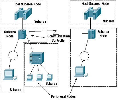
-
host subarea node—A mainframe that runs Advanced Communications Function (ACF)/virtual telecommunications access method (VTAM).
-
communication controller subarea node—A communication controller (a 3705, 3725, 3745, or 3746) that runs ACF/Network Control Program (NCP).
-
peripheral node—Any other node in an SNA network that is not a host or a communications controller.
-
subarea—A subarea node (host or communications controller) plus the peripheral nodes that are directly attached to it. In Figure 1, there are three communication controller subareas and two host subareas.
A subarea node owns its peripheral nodes and it provides network services for the peripheral nodes. All traffic must pass through the subarea node; and the peripheral node can be attached to only one subarea node.
Prerequisites
Requirements
There are no specific requirements for this document.
Components Used
This document is not restricted to specific software or hardware versions.
The information in this document was created from the devices in a specific lab environment. All of the devices used in this document started with a cleared (default) configuration. If your network is live, make sure that you understand the potential impact of any command.
Conventions
For more information on document conventions, refer to the Cisco Technical Tips Conventions.
SNA Network Addressable Units
An SNA network is composed of a number of different network addressable units (NAUs), which define the way that they behave in relation to other components within the SNA network and on entry to the SNA network.
Figure 2 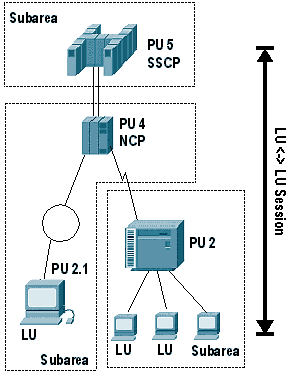
-
network addressable unit (NAU)—An SNA entity that is identified by a unique address, contains SNA functionality to manage its resources, and communicates with other NAUs to manage network resources.
-
physical unit (PU)—Represents a box or a piece of software: an SNA node. The higher the PU number, the greater the function that is contained in the box or software. These are some additional details on the different types of PUs:
-
A PU is an NAU that manages attached resources. PUs are categorized by ability. A PU type 5 has the most ability. It is implemented by VTAM in a host computer. A PU type 5 has the ability to route SNA data between all SNA node types. It also contains a function called the System Services Control Point (SSCP), which is implemented by VTAM. The SSCP has the ability to control network resources, including other PUs and logical units (LUs). All the resources which can be controlled by a single SSCP are defined in the same domain. Therefore, a network which contains multiple SSCPs contains multiple domains.
-
A PU type 4 is implemented by NCP in a communications controller. Examples of communication controllers are the 3705, 3725, 3745, and 3746. A PU type 4 has the ability to route SNA data between all other node types. It does not contain an SSCP, but is under the control of the SSCP.
-
PU types 2 and 1 have limited routing capability. They are always attached to a PU type 4 or 5. They rely upon their attached node to route for them. An LU contained in a PU type 2 or 1 node can not communicate with an LU in another type 2 or 1 node. A PU type 2.1 is associated with Advanced Peer-to-Peer Networking (APPN).
-
A PU type 2.1 has a control point that implements various levels of functionality.
-
-
logical unit (LU)—An NAU that represents an end user to the network. The end user can be either a person or an application program. A typical LU-LU session is between an LU which represents a person and an LU which represents an application program. LU-LU sessions between application programs are also common. LUs are numbered starting with LU 0, 1, 2, 3 and so on and are considered legacy LUs???each with a different amount of functionality. LU 6.2 is the LU type associated with APPN.
These are the various LU types:
-
LU type 0 is for LU-LU communications that are implementation-dependent and that must conform to the network protocols.
-
LU type 1 is used for application programs, for single-device or multiple-device data processing workstations, and for printers that use SNA character string (SCS) data stream.
-
LU type 2 is used for communication between application programs and display workstations in an interactive environment, through the 3270 data stream.
-
LU type 3 is for application programs and printers that use the SNA 3270 data stream.
-
LU type 4 is used for application programs and single-device or multiple-device data processing workstations or word processing workstations that communicate in interactive, batch data transfer or distributed data processing environments. It is also used for peripheral nodes that communicate with each other.
-
LU type 6.1 is for application subsystems that communicate in a distributed data processing environment.
-
LU type 6.2 is for transaction programs that communicate in a distributed data processing environment. LU type 6.2 supports multiple concurrent sessions. The data stream is either an SNA general data stream (GDS) or a user-defined data stream. LU 6.2 can be used for communication between two type 5 nodes, a type 5 node and a type 2.1 node, or two type 2.1 nodes.
-
-
system services control point (SSCP)—Located in a host subarea node, where resources and sessions are controlled. The SSCP is responsible for activating and deactivating SNA resources and for initiating or terminating sessions.
Activating PUs
Figure 3 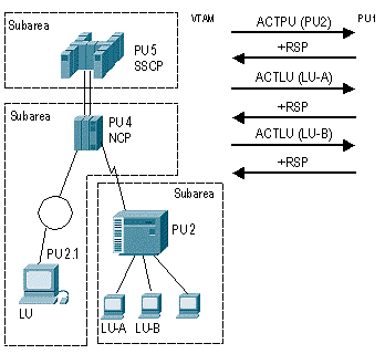
-
When VTAM is activated, the activation sequence for NCPs (PU 4), other PUs, and LUs that are defined as part of the VTAM configuration can begin automatically, or the operator can specifically activate portions of the networks at a particular time from either the operator console or from NetView. In Figure 3, one of these methods has triggered the activation of PU 2, LU-A, and LU-B.
An example of when a portion of a network would be activated at a particular time is when one SSCP takes over the resources from the other SSCP during an outage. In this case, the resources are activated only when the outage occurs.
-
Activate Physical Unit (ACTPU) is the request that activates the SSCP-PU session.
-
Once activated, the session is used to send the Activate Logical Unit (ACTLU) for LUs owned by that PU. It also sends network management information to and from the PU to VTAM or NetView.
In Figure 3, VTAM activates the PU and the two LUs that belong to that PU. In some cases, LUs are intelligent devices or applications and can respond to control flows themselves. In other cases, the PU responds for them.
Activating LU-LU Sessions
Figure 4 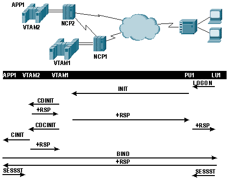
-
Once the LUs are active they can begin to logon to applications. In Figure 4, the user at LU 1 issues a LOGON to application 1, which causes an INITIATE request to be sent to VTAM 1 through the PU.
-
VTAM 1 determines that the application is not located at VTAM 1 (same-domain session), but is located at VTAM 2 (cross-domain session). VTAM1 must notify VTAM2 that a session is requested, so it sends a cross-domain initiate, CDINIT.
-
Once VTAM 2 responds to the CDINIT, VTAM 1 sends a cross-domain control initiate, CDCINIT, which contains session-specific information, including the BIND image.
-
VTAM 2 takes the information in the CDCINIT and passes it to the application in a Control Initiate, CINIT.
-
The application builds the BIND and sends it to LU 1. Once LU 1 responds to the BIND, the session is officially started.
-
Subsequent sessions started (SESSST) messages are sent to the owning VTAMs as part of session awareness.
Routing
Communication beween NAUs in an SNA network occurs through statically defined routes.
Figure 5 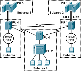
-
In subarea SNA, all routes are statically defined.
-
Between any two subareas, up to eight explicit routes (ERs) can be defined. In this example, explicit route 1 (ER 1) and explicit route 2 (ER 2) represent physical paths between Subarea 2 and Subarea 5.
-
While explicit routes represent physical paths between adjacent subareas, virtual routes represent the logical path between the session end points. The virtual route is mapped to one or more explicit routes that need to be traversed, and up to eight virtual routes can be assigned to an explicit route; each one represents a class of service (CoS).
-
CoS provides prioritization of traffic by application in a SNA environment. The CoS combined with the transmission priority determines the queue and send priorities of session traffic across an explicit route. There are three transmission priorities for LU-LU sessions: high, medium, and low. Combined with CoS, this gives a total of twenty-four levels of prioritization on an explicit route.
-
Virtual and explicit routes define a path between subareas. There can be only one path from a peripheral node to its owning subarea node, so explicit or virtual routes do not apply. This portion of the path is called a route extension.
 Feedback