Channel Interface Processor TCP/IP Redundancy Using VIPA
Available Languages
Contents
Introduction
Virtual IP Address (VIPA) support provides fault tolerance for Multiple Virtual Storage (MVS) by using a virtual device and a virtual IP address in an IBM TCP/IP stack. The virtual device is always active and never sees a failure. The VIPA remains accessible so that RouteD always advertises this IP address (and its subnet) as alive.
The VIPA Program Temporary Fix (PTF) number is UN83939. It has been integrated into TCP/IP Version 3.10.
Prerequisites
Requirements
There are no specific requirements for this document.
Components Used
This document is not restricted to specific software and hardware versions.
The information in this document was created from the devices in a specific lab environment. All of the devices used in this document started with a cleared (default) configuration. If your network is live, make sure that you understand the potential impact of any command.
Conventions
For more information on document conventions, refer to the Cisco Technical Tips Conventions.
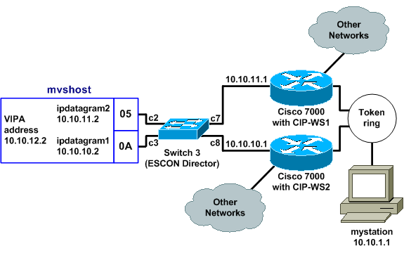
Logical View
In the configuration used in this document, all Telnet, FTP, and other traffic that is initiated from the network side connects through the VIPA address of 10.10.12.2.

Routing Information Protocol (RIP) convergence time (with default settings) could be as much as six minutes. For example, if the Cisco 7000 with CIP-WS2 failed in that topology, it could take as long as six minutes for the traffic that was going through it to begin to go through the Cisco 7000 with CIP-WS1 instead. To decrease the convergence time, the RIP timers on the router can be changed.
TCP Connection Recovery with VIPA
These settings in the configuration for mystation enable TCP connection recovery:
-
Nameserver: mvshost 10.10.12.2 (the destination station and IP address)
-
Destination network: 10.10.12.0 from mystation (paths to that destination station)
-
through 10.10.11.2
-
through 10.10.10.2
-
Assume mystation gets a session with mvshost through 10.10.11.2. If that 10.10.11.2 channel interface on mvshost fails, then this happens:
-
The TCP layer on mystation times out.
-
The TCP layer retransmits.
-
mystation accepts a new route via 10.10.10.2.
-
TCP layer retransmission OK.
Input/Output Configuration Program (IOCP) Configuration
CHPID PATH=05,TYPE=CNC,SWITCH=3
CNTLUNIT CUNUMBR=2300,PATH=05,UNIT=SCTC,LINK=C7,UNITADD=((10,8))
IODEVICE ADDRESS=(310,8),CUNUMBR=2300,UNIT=SCTC
*
CHPID PATH=0A,TYPE=CNC,SWITCH=3
CNTLUNIT CUNUMBR=2400,PATH=05,UNIT=SCTC,LINK=C8,UNITADD=((20,8))
IODEVICE ADDRESS=(320,8),CUNUMBR=2400,UNIT=SCTC
Mainframe TCPIP.Profile File (IP Datagram) - VIPA
000045 DEVICE IPP CLAW 310 CISCOMVS 7000ws1  NONE 20 20 4096 4096
000046 LINK IPL IP 1 IPP
000051 DEVICE I2P CLAW 320 CISCOMVS 7000ws2 NONE 20 20 4096 4096
000052 LINK I2L IP 1 I2P
000057 DEVICE VDEV VIRTUAL 0
000058 LINK VLINK VIRTUAL 0 VDEV
000085 HOME
000087 10.10.11.2     I2L
000089 10.10.10.2     IPL
000091 10.10.12.2     VLINK
000100 BSDROUTINGPARMS true
000101 ; LINK    MAXMTU    METRIC    SUBNET MASK     DEST ADDR
000102   I2L        4096       0      255.255.255.0      10.10.11.1
000103   IPL        4096       0      255.255.255.0      10.10.10.1
000104   VLINK      4096       0      255.255.255.0      0
000108 ENDBSDROUTINGPARMS
000142 START I2P
000144 START IPP
Note: There is no START statement for VDEV (the VIPA device) in the TCPIP.Profile file.
Cisco 7000 with CIP-WS1 Configuration - VIPA
interface Channel0/0
ip address 10.10.11.1 255.255.255.0
ip route-cache cbus
ip route-cache same-interface
no ip redirects
no keepalive
claw C200 10 10.10.11.2 ciscomvs 7000ws1 tcpip tcpip broadcast
Note: This configuration assumes that routing updates are exchanged with the mainframe as the broadcast parameter is specified. If this is not the case, then you must code a static route pointing to the VIPA address using the address specified as the next hop in the CLAW statement. This is an example:
ip route 10.10.12.2 255.255.255.255 10.10.11.2
Cisco 7000 with CIP-WS2 Configuration - VIPA
interface Channel0/0
ip address 10.10.10.1 255.255.255.0
ip route-cache cbus
ip route-cache same-interface
no ip redirects
no keepalive
claw C300 20 10.10.10.2 ciscomvs 7000ws2 tcpip tcpip broadcast
 Feedback