CIP CSNA Description
Available Languages
Contents
Introduction
This document discusses Cisco Systems Network Architecture (CSNA) support on the Channel Interface Processor (CIP) in a Cisco 7000/7500 Router and the Channel Port Adapter (CPA) in a Cisco 7200 Router.
Prerequisites
Requirements
There are no specific requirements for this document.
Components Used
The information in this document is based on the Cisco 7000, 7200 and 7500 Routers.
The information in this document was created from the devices in a specific lab environment. All of the devices used in this document started with a cleared (default) configuration. If your network is live, make sure that you understand the potential impact of any command.
Conventions
Refer to Cisco Technical Tips Conventions for more information on document conventions.
CIP CSNA
CSNA support on the CIP in a Cisco 7000/7500 router and the CPA in a Cisco 7200 router provides mainframe connectivity to Systems Network Architecture (SNA) network nodes. The CIP/CPA supports both ESCON Channel Adapter (ECA) and Parallel Channel Adapter (PCA) connections to an SNA mainframe.
The CSNA feature is designed to provide an SNA LAN gateway to virtual telecommunications access method (VTAM) with the help of a high speed channel connection.
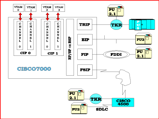
Figure 1 illustrates the LAN/WAN connectivity options that the CSNA feature provides between SNA network nodes and channel-attached mainframes. The CSNA feature also allows you to replace currently-installed IBM 3172 Interconnect Controllers with a either a Cisco 7000/7500 series router equipped with a CIP or a Cisco 7200 series router equipped with a CPA; with no loss of functionality. In fact, you gain functionality, with minimal or no changes to VTAM or site configuration. Likewise, there are many configurations in which a Cisco 7000/7500 router with a CIP or a Cisco 7200 router with a CPA can replace an IBM 3745 or 3746.
Figure 1 – LAN/WAN Connectivity Options 
Hardware
The CSNA feature is a software product and does not introduce any hardware features. However, this feature has a specific hardware requirement. The CSNA feature runs only on a Cisco 7000/7500 series router equipped with one or more CIPs or a Cisco 7200 series router equipped with one or more CPAs.
Software
The CSNA feature allows the router to support connections between a channel-attached SNA mainframe and local LAN-attached SNA nodes, Synchronous Data Link Control (SDLC)- and Qualified Logical Link Control (QLLC)-connected devices, and remotely-connected SNA nodes through remote source-route bridging (RSRB) and data-link switching (DLSw+). Connections between mainframes that are channel-attached to the same router are also supported.
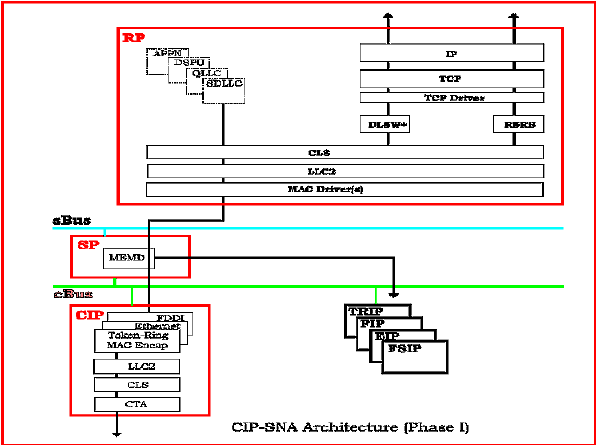
Figure 2 depicts the architecture for the CSNA feature. This feature consists of the CTA driver, ported Cisco Link Services (CLS), Logical Link Control 2 (LLC2) stack, and MAC Encapsulation Layers that run on the CIP/CPA. The CTA driver implements the channel protocol and the primitives necessary to communicate with VTAM over the channel interface and allows VTAM to activate and deactivate SNA nodes through LLC2 as the link level communications. The CLS module provides the interface between the CTA driver and the LLC2 stack which provides the IEEE 802.2 elements of procedure for link level connection establishment and data transfer. The LLC2 stack provides a link station end point for all SNA network nodes that communicate with the channel-attached hosts.
The LLC2 stack on the Route-Switch Processor (RSP) provides LLC2 connection services for QLLC and SDLC Logical Link Control (SDLLC), and RSRB and DLSw+ when local acknowledgment is configured.
The MAC Encapsulation layers provide processing for the LAN media types that the CIP card can accept. There is a MAC encapsulation layer for each media type that you can configure for the CSNA feature, Token Ring, Ethernet, and FDDI. This layer parses the MAC header of every LLC2 frame forwarded to the CIP and destined for the mainframe. The destination MAC address and start of the LLC2 header are determined in the MAC encapsulation layer before the frame is passed to the LLC2 protocol stack. The MAC encapsulation layer also builds the appropriate MAC header type on all LLC2 frames before the layer forwards the frame through the router out onto the network.
Figure 2 – Architecture for the CSNA Feature 
 Feedback