Understanding and Troubleshooting Source-Route Translational Bridging
Contents
Introduction
This document describes Source-Route Translational Bridging (SR/TLB) and provides information to troubleshoot it.
Prerequisites
Requirements
There are no specific requirements for this document.
Components Used
This document is not restricted to specific software and hardware versions.
The information in this document was created from the devices in a specific lab environment. All of the devices used in this document started with a cleared (default) configuration. If your network is live, make sure that you understand the potential impact of any command.
Conventions
For more information on document conventions, refer to the Cisco Technical Tips Conventions.
Source-Route Translational Bridging
It is common for Ethernet environments to mix with Token Ring environments in today's networks. This mix brings a number of logical problems. The first is that Ethernet does not have anything close to source-route bridging, and Token Ring has a Routing Information Field (RIF). Also, Token Rings have functional addresses, while Ethernets most often have broadcasts.
To be able to unite the two environments, Cisco created SR/TLB.
You can add bridge groups to the interfaces of the routers (both Token Ring and Ethernet), to transparently bridge Token Ring and Ethernet. This creates a transparent bridge domain between the two environments. If the Token Ring side is running source-route bridging, there would be a problem. How do you tie the transparent bridging with source-routing, especially given that the end stations are the ones that establish the path through the network?
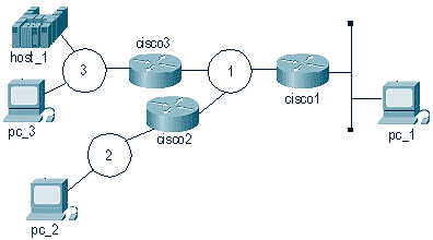
This diagram illustrates the solution:
When pc_1 wants to communicate with pc_3, it sends NetBIOS name_query with a broadcast (FF-FF-FF-FF-FF-FF) packet to the wire. The problem is that the pc_3 station is listening to name_queries with a destination address of (C0-00-00-00-00-80), and it receives that broadcast and does not send it to NetBIOS because it is not a name_query (by pc_3's definition).
This is why the translation from Token Ring to Ethernet can be complicated. Most of the details are handled inside the router, and an issue that creates some confusion is bitswapping. Token Ring and Ethernet read the bits into the adapter in different ways. The router does not go into the frame and change bit order, so MAC addresses on the Ethernet are different from MAC addresses on the Token Ring.
The Ethernet station is not able to act as the source-routed end-station, therefore the Cisco router assumes that role. Based on the previous diagram, these events occur after the router receives the packet from the Ethernet:
-
The cisco1 router receives a packet from the Ethernet. This is from pc_1 to host_1.
-
cisco1 needs a RIF to reach host_1, so it creates an explorer to determine the path to reach host_1.
-
After cisco1 receives the response, it sends the response (without a RIF) to the Ethernet station.
-
pc_1 sends an exchange identification (XID) to the host MAC address.
-
cisco1 gets the Ethernet packet, attaches the RIF to the host, and sends the packet on its way.
-
This process continues.
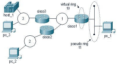
Several conditions make this process possible. First, as far as the host is concerned, the Ethernet is sitting in what is known as a pseudo-ring. This is configured with the source-bridge transparent command on the router:
source-bridge transparent ring-group pseudo-ring bridge-number tb-group [oui]
| Parameter | Description |
|---|---|
| ring-group | The virtual ring group that is created by the source-bridge ring-group command. This is the source-bridge virtual ring to associate with the transparent bridge group. This ring group number must match the number that is specified with the source-bridge ring-group command. The valid range is 1 to 4095. |
| pseudo-ring | The ring number that is used to represent the transparent bridging domain to the source-route bridged domain. This number must be a unique number that is not used by any other ring in the source-route bridged network. |
| bridge-number | The bridge number of the bridge that leads to the transparent bridging domain, from a Token Ring source-routed point of view. |
| tb-group | The number of the transparent bridge group that you want tied into the source-route bridged domain. The no form of this command disables this feature. |
| oui | (Optional) The organizational unique identifier (OUI), which can have values that include these:
|
When you are configuring SR/TLB, you must first have a ring group in the router. The pseudo-ring makes it appear that the Ethernet is Token Ring, from the host_1 point of view.
Configure cisco1 in this manner:
| cisco1 |
|---|
source-bridge ring-group 10 source-bridge transparent 10 11 1 1 ! interface tokenring 0 source-bridge 1 1 10 source-bridge spanning ! interface Ethernet 0 bridge-group 1 ! bridge 1 protocol ieee |
As of Cisco IOS® Software Release 11.2, SR/TLB is fast-switched. Earlier than Cisco IOS Software Release 11.2, SR/TLB was process-switched. To turn off fast-switching, issue this command:
no source-bridge transparent ring-group fastswitch
show Commands
There are two show commands that are important with SR/TLB.
-
show bridge - This command is very useful to analyze the transparent side. It shows if the router is receiving packets from a specific device in the network.
-
show rif - This command shows if the router has built a RIF for the destination MAC address.
Troubleshooting
This sections discuss how to troubleshoot MAC address bitswapping and SR/TLB loops.
Bitswapping
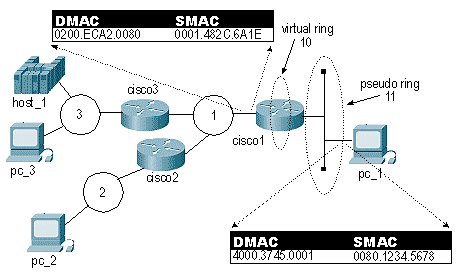
One of the most common causes of problems with SR/TLB is MAC address bitswapping. The problem occurs because the router does a bitswap on MAC addresses from Ethernet to Token Ring and from Token Ring to Ethernet. The result is that end stations are not able to recognize those frames. This diagram shows an example:
In this diagram, the frame has the exact same bit pattern in the Source MAC (SMAC) and Destination MAC (DMAC). This bit pattern is read differently in Token Ring than in Ethernet, however. To be able to send directed frames across this network, you must bitswap them before they are sent.
The first thing to do is to convert the original MAC address to binary. You can use the three 2-byte sets individually to make it easier. This example uses 4000.3745.0001.
4000.3745.0001 has this binary value:
0100 0000 0000 0000 0011 0111 0100 0101 0000 0000 0000 0001
Invert each byte. Do not invert the entire string. This is the binary number separated into bytes:
01000000  00000000  00110111  01000101  00000000  00000001
   40        00        37        45        00        01
To do the bitswap, move the first bit to the last on each of the bytes, and repeat this until the last bit is first:
00000010  00000000  11101100  10100010  00000000  10000000
   02        00        EC        A2        00        80
After the bitswapping is done, you have the new MAC address, which is 0200.ECA2.0080.
The software for many Systems Network Architecture (SNA) Ethernet stations does the swap automatically. If you do not know for sure, it is best to test it both ways.
Note: Sometimes networks include "non-bitswappable" MAC addresses for widely used devices, because the addresses are the same swapped or non-swapped. This means that you need not deal with the coding of the remote FEP address. This is common in Front-End Processor (FEP) environments with many remote sites. For example, 4200.0000.4242 is a non-bitswappable MAC address.
In addition, the router itself - in the transparent bridge portion - treats the MAC addresses as Ethernet format, and the source-routed part of the code treats them as Token Ring format. In scenarios like FDDI, where the frames are read exactly the same, the router code shows the MAC addresses all inverted.
DHCP/BOOTP Support Between Token Ring and Ethernet
DHCP/BOOTP is not supported when you are using SR/TLB or Transparent Bridging (TB) and the server and the client are in different media type LANs (canonical or non-canonical). For example, if the client is in a Token Ring LAN and the server in an Ethernet LAN. This is because the client includes its MAC address in the BOOTP request packet (chaddr field).
For example, when a client with MAC address 4000.1111.0000 sends a BOOTP request and the packet goes through the SR/TLB or TB bridge, the MAC addresses in the MAC header are bitswapped, but the MAC addresses embedded in the BOOTP request are left unchanged. Consequently, the BOOTP packet gets to the server, and the server replies with a BOOTP reply. This BOOTP reply is sent to the broadcast address or to the MAC address of the client, depending on the broadcast flag. In the event that this broadcast flag is not set, the server sends a unicast packet to the MAC address that is specified in the chaddr field. The server on the Ethernet side sends the reply to MAC address 4000.1111.0000. The packet goes through the bridge and the bridge bitswaps the MAC address. Thus, the BOOTP reply on the Token Ring side ends up with a destination MAC address of 0200.8888.0000. Consequently, the client will not recognize this frame.
Loops
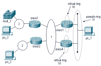
Another cause of SR/TLB problems is that you can not permit the router to use different paths to the same Ethernet.
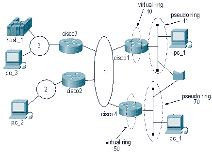
This diagram contains a semi-loop:
Because the packet originates from the same pseudo-ring and is in the same ring group, packets that are coming from the Token Ring environment are sent to the Ethernet. This causes the second SR/TLB router to believe that a certain MAC address is located on its local Ethernet. So, a station on the Ethernet can not reach that station again.
Also, cisco1 will take that same packet and send an explorer to the network, which can make that station appear as if it is on the Ethernet (when it is in the Token Ring environment).
This diagram illustrates a common scenario:
In this case, it takes only one packet to create a huge loop. Because the packet will not be dropped by either the Ethernet side or the Token Ring side, the packet will go endlessly in a looped pattern.
Debugging
Debugging for SR/TLB is very limited. One option is to debug the Token Ring, with filters, to see if the packets are making it through the router. Refer to Understanding and Troubleshooting Local Source-Route Bridging for more information.
 Feedback