Token Ring Bridging and RIF Decoding
Available Languages
Contents
Introduction
This document explains Token Ring bridging and Routing Information Field (RIF) decoding.
Token Ring frames have a similar structure to 802.3 Ethernet and Fiber Distributed Data Interface (FDDI) frames. These frames have destination and source addresses, as well as a Frame Check Sequence (FCS) and a section to carry data. Starting and ending delimiters are also common.

Token Ring frames, but have extra functions built in as well. These include:
-
Routing Information Field (RIF) (optional)
-
Access Control (AC)
-
Frame Control (FC) and the Frame Status (FS) fields
Also, you can use the first bit of the source address in order to indicate the presence of a RIF. But, only one field is relative when you study Source-Route Bridging (SRB).

Prerequisites
Requirements
There are no specific requirements for this document.
Components Used
This document is not restricted to specific software and hardware versions.
Conventions
Refer to Cisco Technical Tips Conventions for more information on document conventions.
Routing Information Fields
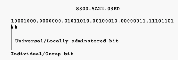
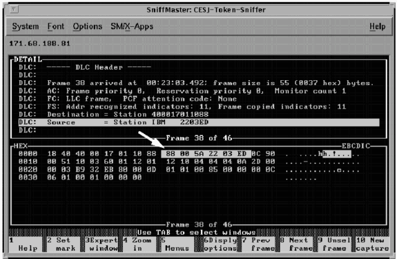
The first bit of the source address must be set to 1 in order to support a RIF.

The RIF is a fairly complicated field. It stores the combination of ring numbers and bridge numbers that a frame crosses between end stations. The RIF also has a two-octet control field that provides various characteristics of the RIF itself. Two stations that communicate over an SRB or a Remote Source-Route Bridging (RSRB) network always use the same RIF for the duration of the session.
The ring-to-bridge portion of the RIF between PC A and PC B in the previous diagram is 00AF.00B0.
Review of MAC Address Structure
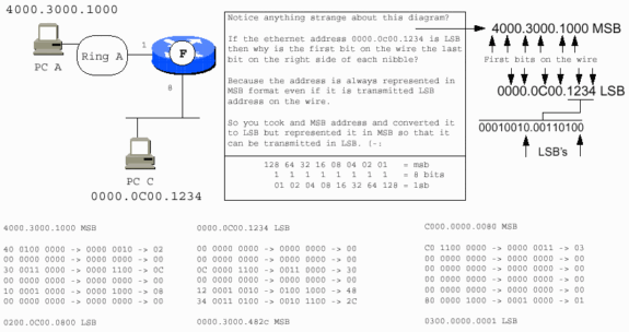
Locally Administered Addresses (LAA) are most commonly seen on Token Ring stations, although it is possible to assign LAAs to Ethernet and FDDI stations. In LAAs, the second bit of the first nibble is set to 1.

One of the skills that is required when you support Token Ring networks is the ability to convert hexadecimal numbering schemes to binary ones when needed. Token Ring provides almost all of its information in hex, but the underlying structure is based on binary digits. The hex representation usually masks some of the underlying structure. You need to be able to convert the hex representation to binary in order to properly interpret the fields with which you work.
This example demonstrates this conversion.

-
Divide the hex number into individual digits:

-
Convert the hex digits to the four binary digits (nibbles) that each hex digit represents:

-
Change the binary nibbles to binary octets:

Hexadecimal Numbering

If the previous address is a destination address, the first bit might be set to 1, which indicates that it is destined for a group or functional address at the receiving stations. Oddly enough, the local/universal bit is set to 1 as is the functional/group address bit. As it is feasible to have a locally administered functional address for Token Ring as well as a universally assigned address, this seems like an oversight on the part of the IEEE 802.5 Committee. Functional and group addresses are beyond the scope of this document as they are not directly applicable to Token Ring bridging. Refer to the document Token Ring/IEEE 802.5 Chapter Goals for more information.

If the previous address is a source address, and the Token Ring frame carries a RIF, the first bit is set to 1. If this is also an LAA, the address starts with 0xC. View the hexadecimal dump of the frame in order to determine this.
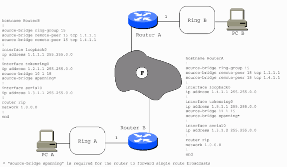
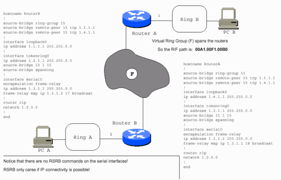
With the exception of some specialized implementations, the WAN in question has no effect on the concept of RSRB. The traffic is carried in IP in most instances. As long as IP can travel between the routers, RSRB operates successfully.
The WAN can be Frame Relay as in this example.
The WAN can be X.25, as in this example.
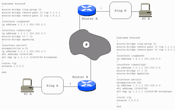
The WAN can be a virtual ring, as in this example.
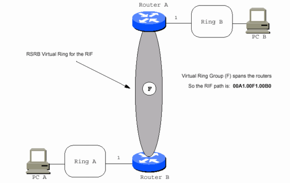
The WAN type is not relevant because the Token Ring frame is safely packaged in TCP/IP, or simply IP, before it reaches the WAN interface. Fast-Sequenced Transport (FST) encapsulation is supported over almost every type of LAN or WAN.
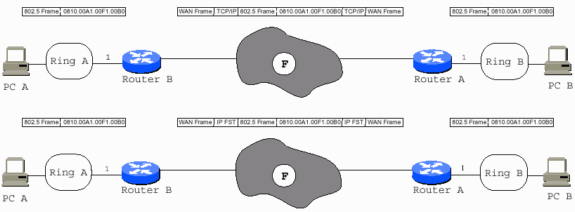
With direct encapsulation, you must ensure that the Maximum Transmission Units (MTUs) of all interfaces in the path are capable to handle the entire 802.5 frame, as direct encapsulation does not allow fragmentation. You need to add an additional 73 bytes, which is for the Cisco RSRB header and other Token Ring overhead, to the maximum Token Ring MTU in the path in order to get the correct MTU for all non-Token Ring interfaces in the path. Serial links require the MTU to be 1573 if the Token Ring MTU is 1500. Only one hop is allowed for direct encapsulation.
In the previous diagram, PC A cannot reach PC B, and PC B cannot reach PC A, unless Router B has RSRB peers (nondirect) with Router A. Router A has RSRB peers with Router B. Routers A and B can also have direct encapsulation set up between them. Router B can be direct to Router A, but not Router C. Router C can be direct to Router A, but Routers B and C need real peers in order to communicate.
Another way to view this is demonstrated in this diagram:

Source-Route Transparent Bridging
Source-Route Transparent Bridging (SRT) was added into the 802.5 specification. It allows 802.5 frames without a RIF to traverse Token Ring interfaces that are configured for transparent bridging. SRT also translates 802.3 to 802.5 for Ethernet Token Ring bridging. It does not resolve the issues of bridging routable protocols over dissimilar media.
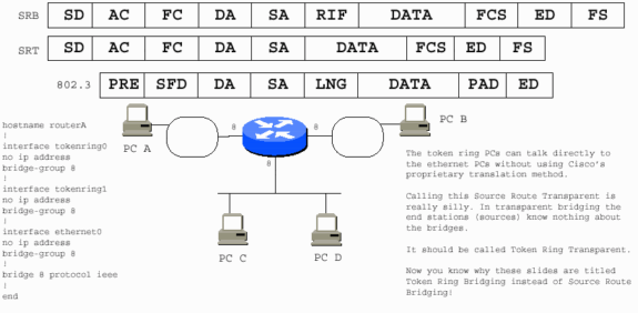
Stations that use SRT cannot communicate with stations that run SRB when they are on separate rings. The two scenarios are fundamentally incompatible. An SRT PC needs the Cisco proprietary solution in order to communicate with an SRB PC.
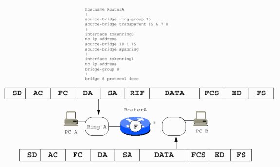
An SRB PC also requires the Cisco solution in order to communicate with an Ethernet PC.
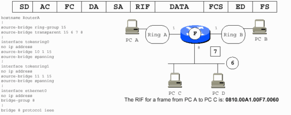
Note: In the previous diagram:
-
6 is the fake ring number used for the Ethernet segment.
-
7 is the fake bridge number that points to the Ethernet segment.
-
The Token Ring PCs assume that the Ethernet PCs are on a Token Ring because they require a valid RIF.
-
The router constitutes the fake part of the RIF, and it adds the RIF to the frames destined for PCs A and B.
-
The Ethernet PCs are not informed that PCs A and B are not on Ethernet. The router strips the RIFs from PC A and PC B frames.
The IEEE has decided to use a bit order transmission scheme for Ethernet that differs from that of Token Ring. The scheme for FDDI Ethernet is Least Significant Bit (LSB) first, while that of FDDI and Token Ring are Most Significant Bit (MSB) first.
Source-Route Bridging
This is a simple scenario that illustrates SRB:

The PCs use source routing, and they need to communicate with each other somehow. The word source in source routing indicates this. But, with transparent bridging, this is not an issue, as transparent bridging is transparent to the end stations. The end stations simply transmit frames as if they can communicate with any station at all. PCs send out explorers in order to help them reach each other.
Explorers
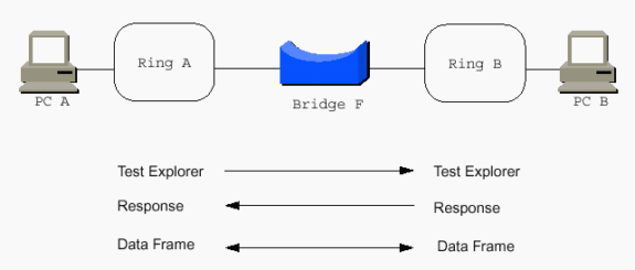
Consider the RIF in the Token Ring frame in order to understand the concept of explorers. The RIF has two primary sections:
-
the control bytes (2)
-
the ring-and-bridge bytes (less than 30)
This is the breakdown of the control bytes:
-
three bits for broadcast type (represented by BBB in this diagram)
-
five bits for the length of the entire RIF (LLLLL) (2*2*2*2*2=32 bytes available)
-
one bit for the direction (D)
-
three bits for the MTU of the connected Token Ring network (FFF)
-
the last four bits for IBM (reserved [RRRR])
This is commonly represented as BBBLLLLL.DFFFRRRR. In addition, BBBLNGTH.DMTURESV is another useful representation of the control bytes.


Keep in mind that IBM works in hexadecimal, and that the source-route path from PC A to PC B is 00AF.00B0. Remember that you have to convert the binary expression of the ring-and-bridge bits to the hexadecimal expression that is used when you work with SRB. This path in binary is 00000000.10101111.00000000.10110000. Broken into binary nibbles, it is 0000.0000.1010.1111.0000.0000.1011.0000. The last bridge number is always 0000, as paths end on rings, not bridges. The rule is that three nibbles make a ring, and one nibble makes a bridge. The ranges are 1-4095 for rings, and 1-15 for bridges.

The ring-and-bridge portion of the RIF is previously discussed. See the Routing Information Fields section for more information. If you add the two control bytes to the original RIF, you end up with 00AF.00B0. The RIF must be at least two bytes long because it requires the control bytes. You have two rings, so you need to add two ring-and-bridge combinations of two bytes each. That makes the RIF six bytes long. Remember, the binary structure of the bytes is BBXLLLLL.DFFFXXXX.RRRRRRRR.RRRRBBBB.RRRRRRRR.RRRRBBBB.
Consider this example, a single-route explorer from PC A to PC B.

The RIF is C670.00AF.00B0. The nibble C670 is always 0.

The single-route explorer RIF appears on Ring B as C610.00AF.00B0, which assumes an MTU of 1500 and assumes it is read from left to right. The direct RIF is 0610.00AF.00B0, which assumes an MTU of 1500 and assumes it is read from left to right. The MTU bits are decremented from 111 (0x7) to the maximum MTU each bridge can handle as the explorer passes through the bridge on its journey. The bridge examines the current value of the MTU bits and, if the value is greater than the bridge supports, the bridge must decrement the value down to the largest MTU it can support. For translational bridging to Ethernet, the maximum MTU is 1500.
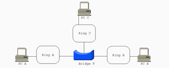
When a multi-port bridge replaces the two-port bridge, more RIFs are possible:
-
PC A to PC C: 0610.00AF.00C0
-
PC A to PC B: 0610.00AF.00B0
-
PC B to PC C: 0610.00BF.00C0
Note: These three are not explorer RIFs. They are directed RIFs with an MTU of 1500 and are read from left to right.
-
PC A to PC B: 0690.00AF.00B0
Note: This is the same RIF as discussed in the previous diagram, but with the D bit set to 1 when read from right to left.
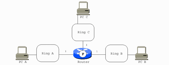
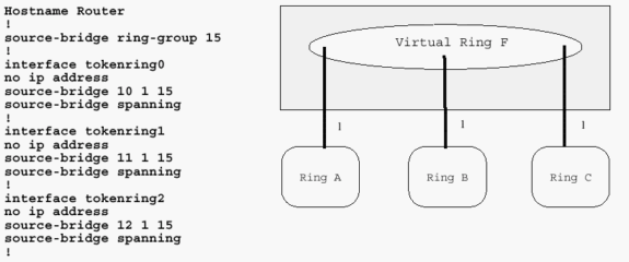
When a multi-port Cisco router replaces the two-port bridge, the router acts as a virtual ring to interconnect the real rings. It adds bridges to the Token Ring interfaces. In most cases, all of the bridge numbers can be 1. The exception is parallel bridges that connect two rings. PC A to PC C is now 0810.00A1.00F1.00C0.
Cisco Router with Three Token Ring Interfaces
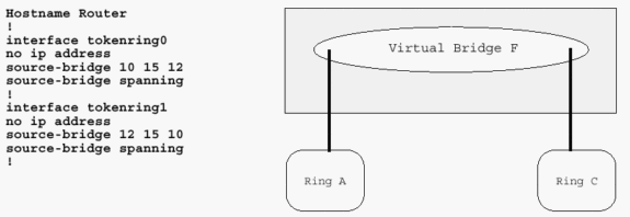
It is possible to have a router with only two Token Ring interfaces, in which case a virtual ring is unnecessary. It is configured similarly to a two-interface bridge, but is not able to perform RSRB.
This diagram demonstrates a Cisco router with two Token Ring interfaces. This router cannot perform RSRB.

The RIF is the most difficult and fundamental aspect of Token Ring SRB. The remainder of this document discusses other ways to achieve Token Ring frames over various network topologies as they make them appear as Token Rings to the RIF. Unless the RIF is terminated, the technology to move the frames from station to station must somehow maintain an accurate RIF. Data-Link Switching (DLSw) is the main implementation that terminates the RIF. This document only addresses implementations in which the RIF is carried end-to-end across the entire network.

These are some general rules to keep in mind:
-
Systems Network Architecture (SNA) devices tend to send out all-routes explorers in search of their chosen destination device. These are unicast to the destination MAC addresses. The destination devices usually reverse the direction bit (D) and send the frame back as a directed frame, not an explorer. SNA has no background broadcast traffic. For example, Front End Processors (FEPs) do not send frames that broadcast their location so that they can be found.
-
Network Basic Input/Output Systems (NetBIOS) send single-route explorers and expect the destination station to reply with an all-routes explorer reply. NetBIOS also performs a large amount of background broadcasting. Devices constantly send frames that communicate their location and other important messages. NetBIOS typically sends its explorers to the NetBIOS functional address for which all NetBIOS stations listen: C000.0000.0080.
-
Most other protocols send their explorers as MAC broadcasts, for example, FFFF.FFFF.FFFF or C000.FFFF.FFFF.
-
Novell can be configured to send single-route or all-routes broadcasts. Stations might need route.com. Servers might need route.nlm.
When you connect two rings with parallel bridges, the bridge numbers must be unique.

Local Acknowledgment
With local-acknowledgment (local-ack), the router becomes involved in an 802.2 Logical Link Control, type 2 (LLC2) session which occurs at the data-link control layer between two end stations. You must understand some of the fundamentals of the 802.2 data-link control layer in order to understand local-ack. The 802.2 is an IEEE and Open System Interconnection (OSI) international standard for communication at the data link layer. The International Organization for Standardization (ISO) specification number is 8802.2. Although many people refer to the OSI seven-layer model during discussions of LANs, a more appropriate model is the IEEE LAN reference model.
With the exception of the OSI protocols (Connection Mode Network Service [CMNS] and Connectionless Network Service [CLNS]) and the International Telecommunication Unit (ITU) protocols such as X.25, most protocols above the data link layer are either proprietary, such as Internetwork Packet Exchange (IPX), AppleTalk, and Digital Equipment Corporation Network (DECnet), or they are standardized by a different body (TCP/IP and the Internet Engineering Task Force [IETF]). Neither the IEEE nor the ITU control the specification of the majority of protocols that run over LANs today.
IEEE LAN Reference Model

The IEEE chose to subdivide the OSI data link layer into two layers. The 802.2 layer has three types of service:
-
connectionless
-
connection-oriented
-
acknowledged connectionless
Type 3 is hardly ever used. Type 2 is used by SNA and NetBIOS. Routable protocols such as IP, IPX, and AppleTalk that are configured for 802.2 use type 1.
802.2 Format
This section discusses some of the key areas of the 802.2 layer.
Service Access Points (SAPs) are used in order to multiplex and demultiplex higher-layer protocols through the 802.2 layer. Typical SAPs are 04 (SNA), F0 (NetBIOS), and E0 (IPX). The control field is two octets in 802.2. It is used for session initialization and termination, flow control, and session supervision. Local-ack mainly handles flow control and session supervision. It only applies to type 2 connection-oriented sessions.

A connection-oriented session acknowledges the frames that are received and indicates the frame number that are sent. For example, the third information frame destined for a session partner that has not yet sent an I frame is sent as I NR0 NS3. This communicates that information frame 3 is to be sent and that the next I frame is expected as sequence number 0. If the session partner has already sent frames 0-4, the I frame is sent as I NR5 NS3. This acknowledges that frames 0-4 have been received and tells the partner that it is OK to send more frames. If, for any reason, a session partner is not capable to receive more frames for a temporary period, the partner can send a supervisory frame to quench the session (for example, S RNR NR5). The NR5 tells the other partner what has been received, and the RNR communicates that the receiver is not ready.
Supervisory frames are also used when the timers that are set in the end stations expire before they receive an acknowledgment of outstanding I frames. The stations can send a supervisory receiver-ready frame that requests that the partner respond immediately. For example, the stations can send S RR NR4 POLL, which assumes that the next frame expected is 4. In this situation, local-ack is useful.
At times, the propagation delay across the WAN can exceed the timer settings in the end systems. This causes the end stations to retransmit the I frames, even though the original frames are delivered and the acknowledgments are returned. Local-ack sends S RR frames to the end station where it originates from, while the RSRB code delivers the frame to the other end system.
Automatic decoding of the RIF can be performed with the RIF Decoder Tool.
Related Information
Contact Cisco
- Open a Support Case

- (Requires a Cisco Service Contract)


 Feedback