Configure Split Tunneling for VPN Clients on the ASA
Available Languages
Download Options
Bias-Free Language
The documentation set for this product strives to use bias-free language. For the purposes of this documentation set, bias-free is defined as language that does not imply discrimination based on age, disability, gender, racial identity, ethnic identity, sexual orientation, socioeconomic status, and intersectionality. Exceptions may be present in the documentation due to language that is hardcoded in the user interfaces of the product software, language used based on RFP documentation, or language that is used by a referenced third-party product. Learn more about how Cisco is using Inclusive Language.
Contents
Introduction
This document describes the process to allow VPN Clients access to the Internet while tunneling into a Cisco ASA 5500 Series Security Appliance.
Prerequisites
Requirements
This document assumes that a working remote access VPN configuration already exists on the ASA. Refer to PIX/ASA 7.x as a Remote VPN Server using ASDM Configuration Example if one is not already configured.
Components Used
The information in this document is based on these software and hardware versions:
-
Cisco ASA 5500 Series Security Appliance Software version 7.x and later
-
Cisco Systems VPN Client version 4.0.5
- Adaptive Security Device Manager (ASDM)

Note: This document also contains the PIX 6.x CLI configuration that is compatible for the Cisco VPN client 3.x.
The information in this document was created from the devices in a specific lab environment. All of the devices used in this document started with a cleared (default) configuration. If your network is live, ensure that you understand the potential impact of any command.
Network Diagram
The VPN Client is located on a typical SOHO network and connects across the Internet to the main office.
 Network Diagram
Related Products
This configuration can also be used with Cisco PIX 500 Series Security Appliance Software version 7.x.
Conventions
Refer to the Cisco Technical Tips Conventions for more information on document conventions.
Background Information
This document provides step-by-step instructions on how to allow VPN Clients access to the Internet while they are tunneled into a Cisco Adaptive Security Appliance (ASA) 5500 Series Security Appliance. This configuration allows VPN Clients secure access to corporate resources via IPsec while giving unsecured access to the Internet.

Note: Full tunneling is considered the most secure configuration because it does not enable simultaneous device access to both the Internet and the corporate LAN. A compromise between full tunneling and split tunneling allows VPN Clients local LAN access only. Refer to PIX/ASA 7.x: Allow Local LAN Access for VPN Clients Configuration Example for more information.
In a basic VPN Client to ASA scenario, all traffic from the VPN Client is encrypted and sent to the ASA no matter what its destination is. Based on your configuration and the number of users supported, such a set up can become bandwidth intensive. Split tunneling can work to alleviate this problem since it allows users to send only that traffic which is destined for the corporate network across the tunnel. All other traffic such as instant messaging, email, or casual browsing is sent out to the Internet via the local LAN of the VPN Client.
Configure Split Tunneling on the ASA
Configure the ASA 7.x with Adaptive Security Device Manager (ASDM) 5.x
Complete these steps in order to configure your tunnel group to allow split tunneling for the users in the group.
-
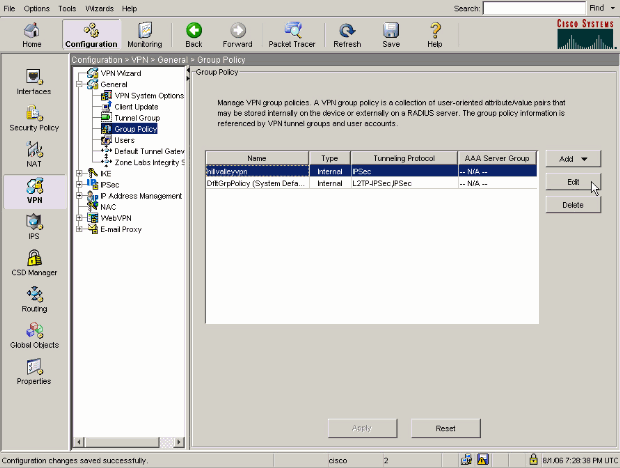
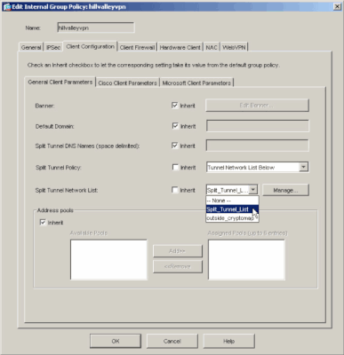
Choose Configuration > VPN > General > Group Policy and select the Group Policy that you wish to enable local LAN access in. Then click Edit .
-
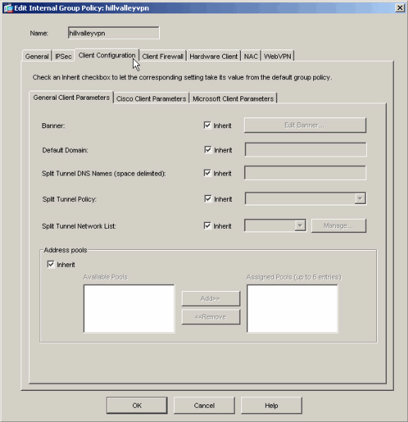
Go to the Client Configuration tab.
-
Uncheck the Inherit box for Split Tunnel Policy and chose
Tunnel Network List Below..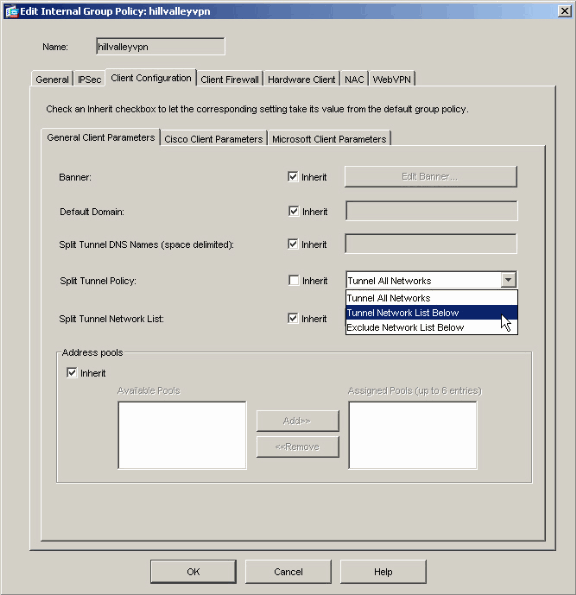
-
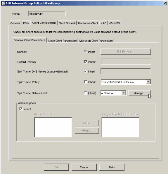
Uncheck the Inherit box for Split Tunnel Network List and then click Manage in order to launch the ACL Manager.
-
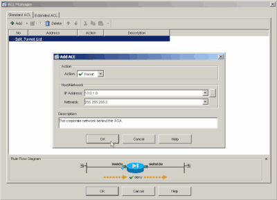
Within the ACL Manager, choose Add > Add ACL... in order to create a new access list.

-
Provide a name for the ACL and click OK.

-
Once the ACL is created, choose Add > Add ACE.. .in order to add an Access Control Entry (ACE).

-
Define the ACE that corresponds to the LAN behind the ASA. In this case, the network is 10.0.1.0/24.
-
Choose Permit .
-
Choose an IP Address of 10.0.1.0
-
Choose a Netmask of 255.255.255.0.
-
(Optional)Provide a description.
-
Click > OK.
-
-
Click OK in order to exit the ACL Manager.

-
Be sure that the ACL you just created is selected for Split Tunnel Network List.
-
Click OK in order to return to the Group Policy configuration.

-
Click Apply and then Send (if required) in order to send the commands to the ASA.

Configure the ASA 8.x with ASDM 6.x
Complete these steps in order to configure your tunnel group to allow split tunneling for the users in the group.
-
Choose Configuration > Remote Access VPN > Network (Client) Access > Group Policies , and choose the Group Policy in which you want to enable local LAN access. Then click Edit.

-
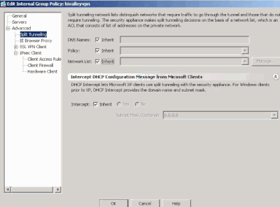
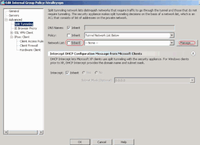
Click Split Tunneling.
-
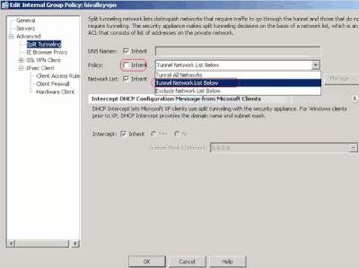
Uncheck the Inherit box for Split Tunnel Policy, and chose Tunnel Network List Below.
-
Uncheck the Inherit box for Split Tunnel Network List, and then click Manage in order to launch the ACL Manager.
-
Within the ACL Manager, choose Add > Add ACL... in order to create a new access list.

-
Provide a name for the ACL, and click OK.

-
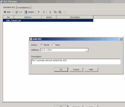
Once the ACL is created, choose Add > Add ACE... in order to add an Access Control Entry (ACE).

-
Define the ACE that corresponds to the LAN behind the ASA. In this case, the network is 10.0.1.0/24.
-
Click the Permit radio button.
-
Choose the network address with mask 10.0.1.0/24.
-
(Optional) Provide a description.
-
Click OK.
-
-
Click OK in order to exit the ACL Manager.

-
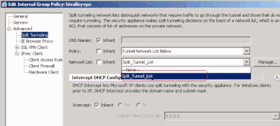
Be sure that the ACL you just created is selected for Split Tunnel Network List.
-
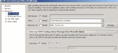
Click OK in order to return to the Group Policy configuration.
-
Click Apply and then Send (if required) in order to send the commands to the ASA.

Configure the ASA 7.x and later via CLI
Rather than use the ASDM, you can complete these steps in the ASA CLI in order to allow split tunneling on the ASA:

Note: The CLI Split Tunneling configuration is the same for both ASA 7.x and 8.x.
-
Enter configuration mode.
ciscoasa>enable
Password: ********
ciscoasa#configure terminal
ciscoasa(config)#
-
Create the access list that defines the network behind the ASA.
ciscoasa(config)# access-list Split_Tunnel_List remark The corporate network behind the ASA.
ciscoasa(config)# access-list Split_Tunnel_List standard permit 10.0.1.0 255.255.255.0
-
Enter Group Policy configuration mode for the policy that you wish to modify.
ciscoasa(config)# group-policy hillvalleyvpn attributes
ciscoasa(config-group-policy)#
-
Specify the split tunnel policy. In this case the policy is tunnelspecified.
ciscoasa(config-group-policy)# split-tunnel-policy tunnelspecified
-
Specify the split tunnel access list. In this case, the list is Split_Tunnel_List.
ciscoasa(config-group-policy)# split-tunnel-network-list value Split_Tunnel_List
-
Issue this command:
ciscoasa(config)# tunnel-group hillvalleyvpn general-attributes
-
Associate the group policy with the tunnel group
ciscoasa(config-tunnel-ipsec)# default-group-policy hillvalleyvpn
-
Exit the two configuration modes.
ciscoasa(config-group-policy)# exit
ciscoasa(config)# exit
ciscoasa#
-
Save the configuration to non-volatile RAM (NVRAM) and press Enter when prompted to specify the source filename.
ciscoasa# copy running-config startup-config

Source filename [running-config]?
Cryptochecksum: 93bb3217 0f60bfa4 c36bbb29 75cf714a

3847 bytes copied in 3.470 secs (1282 bytes/sec)
ciscoasa#
Configure PIX 6.x through the CLI
Complete these steps:
-
Create the access list that defines the network behind the PIX.
PIX(config)#access-list Split_Tunnel_List standard permit 10.0.1.0 255.255.255.0
- Create a vpn group vpn3000 and specify the split tunnel ACL to it as shown:
PIX(config)# vpngroup vpn3000 split-tunnel Split_Tunnel_List

Note: Refer to Cisco Secure PIX Firewall 6.x and Cisco VPN Client 3.5 for Windows with Microsoft Windows 2000 and 2003 IAS RADIUS Authentication for more information on remote access VPN configuration for PIX 6.x.
Verify
Complete the steps in these sections in order to verify your configuration.
Connect with the VPN Client
Connect your VPN Client to the VPN Concentrator in order to verify your configuration.
-
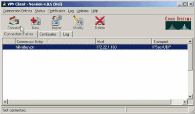
Choose your connection entry from the list and click Connect.
-
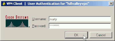
Enter your credentials.
-
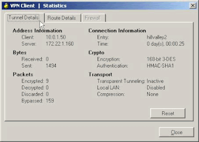
Choose Status > Statistics... in order to display the Tunnel Details window where you can inspect the particulars of the tunnel and see traffic flowing.
-
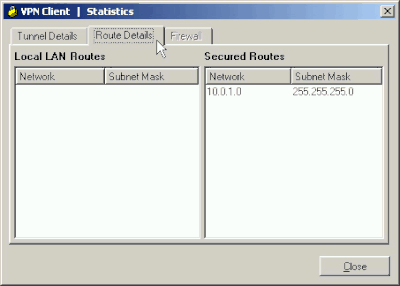
Go to the Route Details tab in order to see the routes that the VPN Client is securing to the ASA.
In this example, the VPN Client is securing access to 10.0.1.0/24 while all other traffic is not encrypted and not sent across the tunnel.
View the VPN Client Log
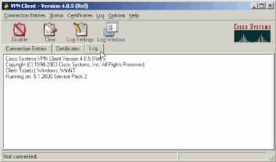
When you examine the VPN Client log, you can determine whether or not the parameter that specifies split tunneling is set. In order to view the log, go to the Log tab in the VPN Client. Then click on Log Settings in order to adjust what is logged. In this example, IKE is set to 3 - High while all other log elements are set to 1 - Low.
Cisco Systems VPN Client Version 4.0.5 (Rel)
Copyright (C) 1998-2003 Cisco Systems, Inc. All Rights Reserved.
Client Type(s): Windows, WinNT
Running on: 5.1.2600 Service Pack 2

1      14:20:09.532  07/27/06  Sev=Info/6	IKE/0x6300003B
Attempting to establish a connection with 172.22.1.160.


!--- Output is supressed


18     14:20:14.188  07/27/06  Sev=Info/5	IKE/0x6300005D
Client sending a firewall request to concentrator

19     14:20:14.188  07/27/06  Sev=Info/5	IKE/0x6300005C
Firewall Policy: Product=Cisco Systems Integrated Client,
Capability= (Centralized Protection Policy).

20     14:20:14.188  07/27/06  Sev=Info/5	IKE/0x6300005C
Firewall Policy: Product=Cisco Intrusion Prevention Security Agent,
Capability= (Are you There?).

21     14:20:14.208  07/27/06  Sev=Info/4	IKE/0x63000013
SENDING >>> ISAKMP OAK TRANS *(HASH, ATTR) to 172.22.1.160

22     14:20:14.208  07/27/06  Sev=Info/5	IKE/0x6300002F
Received ISAKMP packet: peer = 172.22.1.160

23     14:20:14.208  07/27/06  Sev=Info/4	IKE/0x63000014
RECEIVING <<< ISAKMP OAK TRANS *(HASH, ATTR) from 172.22.1.160

24     14:20:14.208  07/27/06  Sev=Info/5	IKE/0x63000010
MODE_CFG_REPLY: Attribute = INTERNAL_IPV4_ADDRESS: , value = 10.0.1.50

25     14:20:14.208  07/27/06  Sev=Info/5	IKE/0x63000010
MODE_CFG_REPLY: Attribute = INTERNAL_IPV4_NETMASK: , value = 255.255.255.0

26     14:20:14.208  07/27/06  Sev=Info/5	IKE/0x6300000D
MODE_CFG_REPLY: Attribute = MODECFG_UNITY_SAVEPWD: , value = 0x00000000

27     14:20:14.208  07/27/06  Sev=Info/5	IKE/0x6300000D
MODE_CFG_REPLY: Attribute = MODECFG_UNITY_PFS: , value = 0x00000000

28     14:20:14.208  07/27/06  Sev=Info/5	IKE/0x6300000E
MODE_CFG_REPLY: Attribute = APPLICATION_VERSION, value = Cisco Systems,
Inc ASA5510 Version 7.2(1) built by root on Wed 31-May-06 14:45

!--- Split tunneling is permitted and the remote LAN is defined.

29     14:20:14.238  07/27/06  Sev=Info/5	IKE/0x6300000D
MODE_CFG_REPLY: Attribute = MODECFG_UNITY_SPLIT_INCLUDE (# of split_nets),
value = 0x00000001

30     14:20:14.238  07/27/06  Sev=Info/5	IKE/0x6300000F
SPLIT_NET #1
	subnet = 10.0.1.0
	mask = 255.255.255.0
	protocol = 0
	src port = 0
	dest port=0

!--- Output is supressed.
Test Local LAN Access with Ping
An additional way to test that the VPN Client is configured for split tunneling while tunneled to the ASA is to use the ping command at the Windows command line. The local LAN of the VPN Client is 192.168.0.0/24 and another host is present on the network with an IP address of 192.168.0.3.
C:\> ping 192.168.0.3
Pinging 192.168.0.3 with 32 bytes of data:

Reply from 192.168.0.3: bytes=32 time<1ms TTL=255
Reply from 192.168.0.3: bytes=32 time<1ms TTL=255
Reply from 192.168.0.3: bytes=32 time<1ms TTL=255
Reply from 192.168.0.3: bytes=32 time<1ms TTL=255

Ping statistics for 192.168.0.3:
    Packets: Sent = 4, Received = 4, Lost = 0 (0% loss),
Approximate round trip times in milli-seconds:
    Minimum = 0ms, Maximum = 0ms, Average = 0ms
Troubleshoot
Limitation with Number of Entries in a Split Tunnel ACL
There is a restriction with the number of entries in an ACL used for split tunnel. It is recommended not to use more than 50-60 ACE entries for satisfactory functionality. You are advised to implement the subnetting feature to cover a range of IP addresses.
Related Information
Revision History
| Revision | Publish Date | Comments |
|---|---|---|
1.0 |
29-Jan-2024 |
Initial Release |
Contributed by Cisco Engineers
Contact Cisco
- Open a Support Case

- (Requires a Cisco Service Contract)
 Feedback