Catalyst 6500 Series WLSM to Catalyst 6500 Series WiSM Migration Guide
Available Languages
Contents
Introduction
This document focuses on the migration strategy from an existing Wireless LAN Services Module (WLSM) to a Wireless Services Module (WiSM). Careful planning and execution is absolutely necessary in the migration from the Cisco WLSM to the Cisco WiSM.
The intended audience for the document includes enterprise network managers and individuals at all levels within the IT infrastructure of an enterprise involved in planning, implementing, or maintaining the WLSM-based wireless networks. A secondary audience includes individuals involved in providing products and integration services, or support to enterprise IT organizations.
Prerequisites
Requirements
There are no specific requirements for this document.
Components Used
The information in this document is based on these software and hardware versions:
-
Cisco Catalyst 6500 Series WLSM
-
Cisco Catalyst 6500 Series WiSM
The information in this document was created from the devices in a specific lab environment. All of the devices used in this document started with a cleared (default) configuration. If your network is live, make sure that you understand the potential impact of any command.
Conventions
Refer to Cisco Technical Tips Conventions for more information on document conventions.
Overview
A migration strategy from the Catalyst WLSM to the Catalyst WiSM platform includes planning and execution of these actions:
-
Plan for and install the Catalyst WiSM.
-
Install the Catalyst WiSM platform.
-
Install the Cisco Wireless Control System (WCS) network management platform for the Catalyst WiSM.
-
Migrate the configurations from the Catalyst WLSM to the Catalyst WiSM-based platform to continue support of all lightweight and converted autonomous access points.
-
Migrate the autonomous IOS® access points to the Lightweight Access Point Protocol (LWAPP)-enabled IOS platform (beyond the scope of the document).
-
Train the support personnel on the Catalyst WiSM platform and solution.
-
Clean up the legacy configurations when the migration is complete.
Architectural Differences
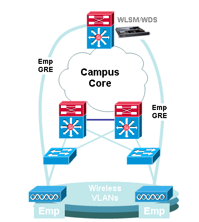
Cisco Catalyst 6500 Series WLSM
The Cisco Catalyst 6500 Series WLSM can be installed and configured in any open slot of a 3-, 6-, 9-, or 13-slot Cisco Catalyst 6500 Series Switch equipped with a Supervisor Engine 720. The Cisco Catalyst 6500 Series WLSM works with Cisco Aironet autonomous access points and the Cisco Works Wireless LAN Solution Engine (WLSE).
The Cisco Catalyst 6500 Series WLSM is typically deployed in the distribution layer or the data center. It is rarely deployed in the wiring closet. An autonomous access point connects to any switch port on any Layer 3 network. Upstream switches or routers do not have to be configured and no specific VLAN assignment or trunks are required. Before traffic is actively passed, the autonomous access point can be authenticated as a trusted network device.
One of the most important concepts introduced with the use of the WLSM is the mobility group. A wireless client experiences seamless roaming (maintains all its IP sessions) when it moves between two access points configured to be a part of the same mobility group. A mobility group is defined on the access point by a unique mapping between the service set identifier (SSID) for the radio side and the network ID for the wired side. The network ID represents the overlaid logical network built on top of the existing infrastructure using Generic Routing Encapsulation (GRE) tunnels, and its mapping to the SSID replaces that between the SSID and the VLAN ID.
Refer to the Cisco Catalyst 6500 Series Wireless LAN Services Module (WLSM) Deployment Guide for detailed information on how to configure and deploy the WLSM.

Note that a VLAN is still associated with each SSID. These VLANs are now defined only on the access point and do not need to be configured on the access layer or distribution layer switches. The only purpose of the VLAN portion of the configuration is to provide a binding between the encryption associated with the VLAN to a specific SSID.
dot11 vlan-name Emp vlan 3 ! dot11 ssid Employee vlan 3 authentication open eap eap_methods authentication network-eap eap_methods authentication key-management wpa mobility network-id 3 ! interface Dot11Radio0 no ip address no ip route-cache ! encryption vlan 3 mode ciphers tkip ! ssid Employee |
interface Tunnel3 description mGRE for employees ip address 10.10.3.1 255.255.255.0 no ip redirects ip mtu 1476 ip dhcp snooping packets tunnel source Loopback3 tunnel mode gre multipoint mobility network-id 3 ! |
Cisco Catalyst 6500 Series WiSM
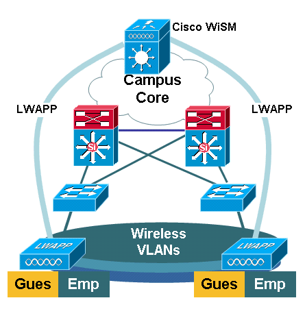
The Cisco Catalyst 6500 Series WiSM is a member of the Cisco Wireless LAN Controller (WLC) family also called Cisco Unified Wireless Networks. The Cisco WiSM works in conjunction with Cisco Aironet lightweight access points (LAPs) and the Cisco WCS. The Cisco WiSM integrates smoothly into existing Cisco Catalyst 6500 Series Enterprise Networks. It scales to deliver secure, enterprise wireless access to main, branch, and remote campuses. It communicates using the LWAPP in order to establish secure connectivity between access points and modules across Layer 3 networks. From a traffic handling point of view, all data traffic that originates from wireless clients associated to the LAPs are encapsulated by the access points themselves and carried to a WLC, which aggregates the traffic and represents the single point of ingress and egress for IP traffic to and from the wired network.
However, these differences exist:
-
Traffic is tunneled from the access points to the centralized controller, which leverages LWAPP and not GRE.
-
Both control and data traffic is carried via LWAPP. Data traffic uses UDP port 12222, control traffic is encapsulated in UDP port 12223, and mobility messages use UDP ports 16666/16667.
-
The control traffic is Advanced Encryption Standard (AES)-encrypted, and the data is in the clear.
-
There is not a separate logical tunnel for each defined SSID. Only a single logical tunnel is built between each access point and the WLC. This LWAPP tunnel is used to carry the data traffic for all the wireless clients associated to the access point, regardless of the SSID they are associated with.

Migration Strategy
Upgrade Product Software
Upgrade the software on these products:
-
Supervisor 720 needs to run Cisco IOS Software Release 12.2(18)SXF2 or later
-
Catalyst 6500 WLSM needs to run 1.4.1 or later
-
Catalyst 6500 WiSM needs to run 3.2.78.4 or later
-
Cisco Aironet access points need to run Cisco IOS Software Release 12.3.7JA2 or later (in order to be converted to LWAPP)
Implement Configurations
Implement these configurations:
-
Configure the Supervisor 720 to support the Cisco WiSM.
-
Configure the VLAN for the WiSM management interface on the Supervisor 720.
-
Configure the VLAN for the dynamic interface of the WiSM on the Supervisor 720.
-
Configure DHCP to scope for the service interface or statically configure the IP address.
-
Test the new Layer 3 networks for routing issues.
Refer to the Cisco WiSM Configuration Guide and Troubleshoot and Configure Initial Wireless Services Module (WiSM) Setup for details on how to complete these configurations.
Configure the Catalyst 6500 WiSM to Migrate the SSID from the Catalyst 6500 WLSM
In the case of Cisco WLSM architecture, the SSID configured on an access point is mapped to a mobility network that tunnels all client traffic to the Catalyst 6500. These multipoint GRE (mGRE)) tunnels have a single termination point on the Supervisor 720 module of the Catalyst 6500 that hosts the WLSM. The other logical endpoint of the tunnel exists on all access points that participate in the Layer 3 mobility network. In the case of a Cisco WiSM platform, the SSID is represented as WLAN. Each WLAN is associated to the management interface or an operator-defined dynamic interface. The operator-defined dynamic interfaces are analogous to VLANs and act as a DHCP relay for wireless clients.
One mGRE tunnel must be defined on the Supervisor 720 module for each mobility group. Here is an example of an mGRE tunnel interface on a Supervisor 720. All wireless clients use the IP address of the tunnel interface as the default gateway. The mobility network-id defines this as a unique mobility network. The mobility network-id defined for this tunnel is also defined under one of the access point SSID definitions in order to identify its participation in this Layer 3 mobility network.
Note: A mobility group is a group of wireless clients that are grouped together for some shared characteristic such as a common authentication or encryption scheme, or user types such as visitors and employees.
This output shows the configuration on the Supervisor 720:
interface Tunnel172
 description to_wireless_clients
 ip address 172.16.1.1 255.255.255.0
 ip helper-address 10.1.1.11
 no ip redirects
 ip dhcp snooping packets
 tunnel source Loopback100
 tunnel mode gre multipoint
 mobility network-id 172
This output shows the corresponding configuration on the access point:
interface Dot11Radio0
 no ip address
 no ip route-cache
 !
 encryption vlan 172 mode ciphers tkip
 !
 ssid light
    vlan 172
    authentication network-eap eap_methods
    authentication key-management wpa
    mobility-network-id 172
In order to convert this configuration to the WiSM architecture, you need to create a new dynamic / VLAN interface, assign it an IP address on a different subnet, and associate it with a WLAN.
The WLAN interface name corresponds to the SSID name on the Cisco Aironet access points. In this example it is "light". When you maintain a similar name, the user experience is minimal. The only difference is the IP address segment from where the wireless clients are assigned an IP address.
-
Create the new VLAN in the Supervisor 720 and add it to the VLAN database.
c6506-t(config)#interface vlan 45
c6506-t(config-if)#ip add 172.16.2.1 255.255.255.0
c6506-t(config-if)#no shut
c6506-t(config-if)#end
c6506-t(config)#vlan 45
c6506-t(config-vlan)#state active
c6506-t(config-if)#end
-
Allow the VLAN in the trunked gigabit interfaces.
c6506-t(config)#interface range gig 1/1-4
c6506-t(config-if-range)#switchport mode trunk
c6506-t(config-if-range)#switchport trunk encap dot1q
c6506-t(config-if-range)#switchport trunk native vlan 201
c6506-t(config-if-range)#switchport trunk allowed vlan 201,45
c6506-t(config-if-range)#mls qos trust dscp
c6506-t(config-if-range)#spanning-tree portfast
c6506-t(config-if-range)#channel-group 1 mode on
c6506-t(config-if-range)#end
-
Once the VLAN is allowed in the trunked interface, it is allowed automatically in the port-channel interface.
c6506-t#show run interface port-channel 1
!
interface Port-channel1
 switchport
 switchport trunk encapsulation dot1q
 switchport trunk native vlan 201
 switchport trunk allowed vlan 45,201
 switchport mode trunk
 no ip address
end
c6506-t#
-
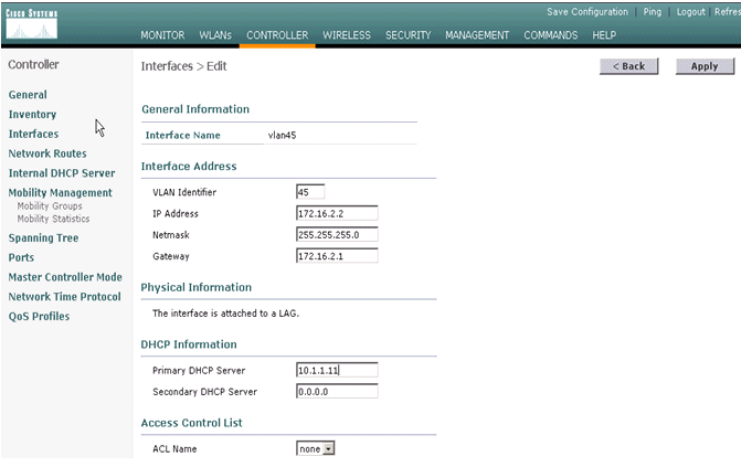
Complete these steps in order to create the dynamic interface in the Catalyst 6500 WiSM through the web interface.
-
Choose Controller > Interfaces and click New.

-
Enter an interface name and VLAN ID and click Apply.

-
Enter the appropriate IP address information and the DHCP server information and click Apply.

-
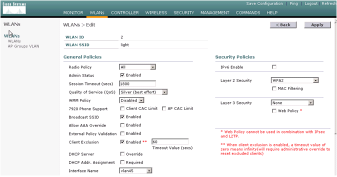
Choose WLANs and click New in order to add a new SSID on the Cisco WiSM.

-
Add the SSID light and click Apply.

-
Change the interface name parameter to the appropriate VLAN.
Other security parameters, such as the appropriate RADIUS server and encryption settings should correspond to the configuration on the Cisco Autonomous Access Point. In this example, the Interface name is changed to VLAN45 and the Layer 2 security type is changed to WPA2.

Here is the new SSID light.

-
If a new SSID is used, no other configurations are required. If an existing SSID is used, upgrade only one RF domain at a time in order to prevent mobility issues between the Catalyst 6500 WSLM and Catalyst 6500 WiSM.
-
Once the WLANs are configured, check if the WLAN policies are correct. For example, ACL, QoS, and so forth.
-
Make sure Cisco WCS is up and running and is ready to be configured to manage the Cisco WiSM.
-
LWAPP Conversion of the Access Point
Migration from autonomous access point mode to lightweight mode is possible on these Cisco Aironet access point platforms:
-
All Cisco Aironet 1130 AG Access Points
-
All Cisco Aironet 1240 AG Access Points
-
For all IOS-based 1200 Series Modular Access Point (1200/1220 Cisco IOS Software Upgrade, 1210 and 1230 AP) platforms, it depends on the radio:
-
if 802.11G, MP21G and MP31G are supported
-
if 802.11A, CB21A and CB22A are supported
-
-
The Cisco Aironet 1200 Series Access Points can be upgraded with any combination of supported radios—G only, A only, or both G and A.
. Access points must run Cisco IOS Software Release 12.3(7)JA or later before you can perform the upgrade. Refer to Upgrading Autonomous Cisco Aironet Access Points to Lightweight Mode for more information on the conversion procedure.
Access Point Distribution Among Controllers on the Cisco WiSM
If an access point is already configured with a static IP address, the access point retains the IP address after it is converted from the autonomous mode to the LWAPP mode. If the access point is not on the same Layer 2 IP subnet as the controller, then DNS resolution of CISCO-LWAPP-CONTROLLER@localdomain is the only guaranteed controller discovery mechanism. The upgrade utility can configure a name server before you load Cisco IOS Software Release 12.3(7)JX. Verify that the name server can properly resolve CISCO-LWAPP-CONTROLLER@localdomain before you start the upgrade procedures.
You can also use the vendor-specific DHCP option 43 to return one or more controller IP addresses to an access point in the DHCP offer message. The access point sends an LWAPP discovery message to the management IP address of the controller it receives in DHCP option 43. Refer to Appendix A: Configuring DHCP Option 43 for Lightweight Cisco Aironet Access Points on Windows 2003 Enterprise DHCP Server for more information on how to configure DHCP option 43 in a Windows 2003 Enterprise DHCP Server.
Test with a Limited Number of Access Points
Start the migration process with a single access point at a location which is easily accessible by the administrator and then attempt to do a remote location. Once access points are converted to LWAPP mode and the Cisco WiSM configuration is completed, test the wireless clients for:
-
Security settings
-
Standard applications like email, Internet access, database applications, and so forth
-
Smooth roaming between access points and check to see if the clients retain the IP addresses while roaming between access points.
-
Any Transmission Control Protocol (TCP) Maximum Segment Size (MSS) issues—download large Internet pages or transfer files using File Transfer Protocol (FTP).
-
Acceptable throughput from the wireless access points as per design
Full Deployment
In order to move quickly through larger access point numbers, install the upgrade utility on more than one machine for the simultaneous conversion of multiple autonomous access points to LWAPP-capable access points.
Troubleshoot
Follow normal troubleshooting procedure for specific problems in the WLC. Refer to Wireless LAN Controller (WLC) Troubleshoot FAQ for more details on troubleshooting.
Related Information
Revision History
| Revision | Publish Date | Comments |
|---|---|---|
1.0 |
16-Nov-2006 |
Initial Release |
Contact Cisco
- Open a Support Case

- (Requires a Cisco Service Contract)


 Feedback