Dynamic Layer 3 VPNs with Multipoint GRE Tunnels Configuration Example
Available Languages
Contents
Introduction
This document describes how to configure Dynamic Layer 3 (L3) VPNs with the multipoint Generic Routing Encapsulation (mGRE) Tunnels feature.
Prerequisites
Requirements
Before you configure Dynamic L3 VPNs with the mGRE Tunnels feature, ensure that your Multiprotocol Label Switching (MPLS) VPN is configured and works properly, and that end-to-end connectivity is established for the IPV4 network.
Components Used
The information in this document is based on these software and hardware versions:
- Cisco 7206VXR (NPE-G1) Series Router with Cisco IOS® Software Release 15.2(4)S3
- Cisco 7609-S Series Router with Cisco IOS Software Release 12.2(33)SRE4
The information in this document was created from the devices in a specific lab environment. All of the devices used in this document started with a cleared (default) configuration. If your network is live, make sure that you understand the potential impact of any command.
Background Information
The Dynamic L3 VPNs with mGRE Tunnels feature provides an L3 transport mechanism based on an enhanced mGRE tunneling technology for use in IP networks. The dynamic L3 tunneling transport can also be used within IP networks in order to transport VPN traffic across service provider and enterprise networks, and to provide interoperability for packet transport between IP and MPLS VPNs. This feature provides support for RFC 2547, which defines the outsourcing of IP backbone services for enterprise networks.
Restrictions for Dynamic L3 VPNs with mGRE Tunnels
Here is a list of restrictions that apply for Dynamic L3 VPNs with mGRE tunnels:
- The deployment of an MPLS VPN with both IP/GRE and MPLS encapsulation within a single network is not supported.
- Each Provider Edge (PE) router supports one tunnel configuration only.
- The VLAN interface on the Cisco 7600 Series router that faces towards the core where tunnelled tag traffic must enter is not supported. It should be the main interface or a subinterface.
- MPLS VPN over mGRE is supported on the Cisco 7600 Series routers that use the ES-40 line card and the Session Initiation Protocol (SIP) 400 line card as core-facing cards.
Configure
This section describes two configurations:
- Dynamic L3 VPN with mGRE tunnels on IP-only network
- Dynamic L3 VPN with mGRE tunnels on IP + MPLS network
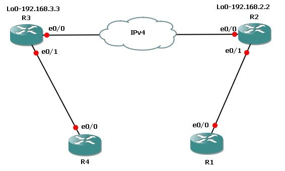
Dynamic L3 VPNs with mGRE Tunnels on IP-Only (Non-MPLS) Network
Network Diagram

Configurations
These are the required configurations on Router 3 (R3) and Router 2 (R2).
Here is the configuration for R3:
l3vpn encapsulation ip MGRE
transport ipv4 source Loopback0

route-map MGRE-NEXT-HOP permit 10
set ip next-hop encapsulate l3vpn MGRE

router bgp 65534
 !
address-family vpnv4
neighbor 192.168.2.2 route-map MGRE-NEXT-HOP in
Here is the configuration for R2:
l3vpn encapsulation ip MGRE
transport ipv4 source Loopback0

route-map MGRE-NEXT-HOP permit 10
set ip next-hop encapsulate l3vpn MGRE

router bgp 65534
 !
address-family vpnv4
neighbor 192.168.3.3 route-map MGRE-NEXT-HOP in
Verify
Use this section in order to confirm that your configuration works properly.
R2#show tunnel endpoints

 Tunnel0 running in multi-GRE/IP mode

 Endpoint transport 192.168.3.3 Refcount 3 Base 0x1E8E1B74 Create Time 00:47:53
   overlay 192.168.3.3 Refcount 2 Parent 0x1E8E1B74 Create Time 00:47:53


R2#show l3vpn encapsulation ip MGRE

 Profile: MGRE
    transport ipv4 source Loopback0
    protocol gre
    payload mpls
    mtu default
  Tunnel Tunnel0 Created [OK]
  Tunnel Linestate [OK]
  Tunnel Transport Source Loopback0 [OK]


R2#show ip route vrf MGRE 172.16.3.3

Routing Table: MGRE
Routing entry for 172.16.3.3
  Known via "bgp 65534", distance 200, metric 0, type internal
  Last update from 192.168.3.3 on Tunnel0, 01:03:25 ago
  Routing Descriptor Blocks:
  * 192.168.3.3 (default), from 172.16.112.1, 01:03:25 ago, via Tunnel0 <points to tunnel
      Route metric is 0, traffic share count is 1
      AS Hops 0
     MPLS label: 17   <BGP vpnv4 label>
      MPLS Flags: MPLS Required
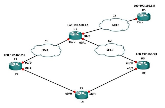
Dynamic L3 VPNs with mGRE Tunnels on IP + MPLS Network
Network Diagram

If you have a dual connection scenario where one connection is MPLS and the other is non-MPLS, you must configure mGRE on all PE routers involved. With this topology, you must configure mGRE on all three PE routers.
If you have not configured mGRE on the connection between R3 and R1 - MPLS link, then the subnets behind R3 are not able to communicate with the subnets behind R2.
R1 and R2 build tunnel endpoints with R3 based on the L3 VPN profile. Refer to the configuration in this document where the L3 VPN profile is not configured, the route-map to the Border Gateway Protocol (BGP) peer on R3 is not applied, and the route-map for the L3 VPN for R3 on R1 is not applied.
Configurations
These are the required configurations on R1, R2, and R3.
Here is the configuration for R1:
l3vpn encapsulation ip MGRE
transport ipv4 source Loopback0

route-map MGRE-NEXT-HOP permit 10
set ip next-hop encapsulate l3vpn MGRE

router bgp 65534
address-family vpnv4
neighbor 192.168.2.2 send-community extended
neighbor 192.168.2.2 route-map MGRE-NEXT-HOP in
neighbor 192.168.3.3 activate
Here is the configuration for R2:
l3vpn encapsulation ip MGRE
transport ipv4 source Loopback0

route-map MGRE-NEXT-HOP permit 10
set ip next-hop encapsulate l3vpn MGRE

router bgp 65534
address-family vpnv4
neighbor 192.168.1.1 route-map MGRE-NEXT-HOP in
neighbor 192.168.1.1 activate
Here is the configuration for R3:
router bgp 65534
address-family vpnv4
neighbor 192.168.1.1 activate
Verify
Now, you can ping from the R2 loopback1 to the R3 loopback1:
R2#ping vrf  MGRE  172.16.3.3 source 172.16.2.2

Type escape sequence to abort.
Sending 5, 100-byte ICMP Echos to 172.16.3.3, timeout is 2 seconds:
Packet sent with a source address of 172.16.2.2
.....
Success rate is 0 percent (0/5)


R2#show ip route vrf MGRE 172.16.3.3

Routing Table: MGRE
Routing entry for 172.16.3.3/32
  Known via "bgp 65534", distance 200, metric 0, type internal
  Last update from 192.168.3.3 on Tunnel0, 00:50:23 ago
  Routing Descriptor Blocks:
  * 192.168.3.3 (default), from 192.168.1.1, 00:50:23 ago, via Tunnel0  <it is
    pointed towards a tunnel>
      Route metric is 0, traffic share count is 1
      AS Hops 0
      MPLS label: 19
      MPLS Flags: MPLS Required


R2#show tunnel endpoints
 Tunnel1 running in multi-GRE/IP mode

 Tunnel0 running in multi-GRE/IP mode

 Endpoint transport 192.168.1.1 Refcount 3 Base 0x507665E4 Create Time 01:24:25
   overlay 192.168.1.1 Refcount 2 Parent 0x507665E4 Create Time 01:24:25
 Endpoint transport 192.168.3.3 Refcount 3 Base 0x507664D4 Create Time 00:50:51
   overlay 192.168.3.3 Refcount 2 Parent 0x507664D4 Create Time 00:50:51
R2 created a dynamic tunnel for 192.168.3.3 based on the BGP next-hop for the 172.16.3.3 route.
R2#show ip bgp vpnv4 vrf  MGRE 172.16.3.3
BGP routing table entry for 43984:300:172.16.3.3/32, version 29
Paths: (1 available, best #1, table MGRE)
  Advertised to update-groups:
     1
  Local, imported path from 300:300:172.16.3.3/32
    192.168.3.3 (metric 3) (via Tunnel0) from 192.168.1.1 (192.168.1.1)
      Origin incomplete, metric 0, localpref 100, valid, internal, best
      Extended Community: RT:43984:300
      Originator: 192.168.3.3, Cluster list: 192.168.1.1
      mpls labels in/out nolabel/19
It is verified on R1, and it also created tunnel endpoints for both PE routers:
R1#show tunnel endpoints
 Tunnel1 running in multi-GRE/IP mode

 Tunnel0 running in multi-GRE/IP mode

 Endpoint transport 192.168.2.2 Refcount 3 Base 0x1E8EE7B0 Create Time 01:36:41
   overlay 192.168.2.2 Refcount 2 Parent 0x1E8EE7B0 Create Time 01:36:41
 Endpoint transport 192.168.3.3 Refcount 3 Base 0x1E8EE590 Create Time 00:59:34
   overlay 192.168.3.3 Refcount 2 Parent 0x1E8EE590 Create Time 00:59:34
On R3, no tunnel endpoints are created:
R3#show tunnel endpoints
Here is the route for the R2 subnet, which originated the ping:
R3#show ip route vrf  MGRE  172.16.2.2

Routing Table: MGRE
Routing entry for 172.16.2.2/32
  Known via "bgp 65534", distance 200, metric 0, type internal
  Last update from 192.168.2.2 01:01:57 ago
  Routing Descriptor Blocks:
  * 192.168.2.2 (default), from 192.168.1.1, 01:01:57 ago
      Route metric is 0, traffic share count is 1
      AS Hops 0
      MPLS label: 17
      MPLS Flags: MPLS Required
Hence, the packet is sent encapsulated in GRE towards R3. Since R3 has no tunnel, it does not accept the GRE packet, and drops it.
Therefore, you must configure mGRE end-to-end on a path in order to make it work. Here is the configuration for mGRE on R3, which is necessary:
l3vpn encapsulation ip MGRE
transport ipv4 source Loopback0

route-map MGRE-NEXT-HOP permit 10
set ip next-hop encapsulate l3vpn MGRE
As soon as you create the L3 VPN profile, tunnel endpoints are created, and you receive the traffic that was dropped earlier. However, return traffic is MPLS and not GRE untill you apply the profile on the BGP peer. That traffic is dropped on R1, because R1 does not have any label information for R2, which runs only IP.
R3#show tunnel endpoints
 Tunnel0 running in multi-GRE/IP mode

 Endpoint transport 192.168.1.1 Refcount 3 Base 0x2B79FBD4 Create Time 00:00:02
   overlay 192.168.1.1 Refcount 2 Parent 0x2B79FBD4 Create Time 00:00:02
 Endpoint transport 192.168.2.2 Refcount 3 Base 0x2B79FAC4 Create Time 00:00:02
   overlay 192.168.2.2 Refcount 2 Parent 0x2B79FAC4 Create Time 00:00:02


R3#show ip cef vrf  MGRE  172.16.2.2
172.16.2.2/32
  nexthop 192.168.13.1 GigabitEthernet0/0.1503 label 21 17

  router bgp 65534
address-family vpnv4
neighbor 192.168.1.1 route-map MGRE-NEXT-HOP in


R3#show ip cef vrf  MGRE  172.16.2.2
172.16.2.2/32
  nexthop 192.168.2.2 Tunnel0 label 17 <exit interface is tunnel and only vpnv4 label is left>


R2#ping vrf  MGRE 172.16.3.3 source  172.16.2.2

Type escape sequence to abort.
Sending 5, 100-byte ICMP Echos to 172.16.3.3, timeout is 2 seconds:
Packet sent with a source address of 172.16.2.2
!!!!!
Success rate is 100 percent (5/5), round-trip min/avg/max = 1/1/4 ms
Scenario 3

Suppose subnets behind R5, which need to communicate with R3, do not want to use mGRE. Then, you can use the route-map that was used for the L3 VPN profile in order to set the next-hop and call a prefix-list, and only permit the prefixes that need the mGRE tunnel.
Here is the configuration for R1:
route-map MGRE-NEXT-HOP permit 10
 match ip address prefix-list test
 set ip next-hop encapsulate l3vpn MGRE
route-map MGRE-NEXT-HOP permit 20
You can permit prefixes in the prefix-list test that need the mGRE tunnel, and everything else does not have a tunnel as an exit interface and follows normal routing. This configuration works because R3 and R5 have MPLS connectivity end-to-end.
Troubleshoot
There is currently no specific troubleshooting information available for this configuration.
Related Information
Revision History
| Revision | Publish Date | Comments |
|---|---|---|
1.0 |
29-Oct-2013 |
Initial Release |
 Feedback