Configure Design and Migration Best Practices for Segment Routing over IPv6
Available Languages
Download Options
Bias-Free Language
The documentation set for this product strives to use bias-free language. For the purposes of this documentation set, bias-free is defined as language that does not imply discrimination based on age, disability, gender, racial identity, ethnic identity, sexual orientation, socioeconomic status, and intersectionality. Exceptions may be present in the documentation due to language that is hardcoded in the user interfaces of the product software, language used based on RFP documentation, or language that is used by a referenced third-party product. Learn more about how Cisco is using Inclusive Language.
Contents
Introduction
This document describes Segment Routing over IPv6 (SRv6) design guidelines and deployment best practices. It also covers a seamless migration strategy.
Background Information
SRv6 introduces a level of simplification with the use of the IPv6 data plane and the concept of network programming. The SRv6 architecture described in RFC 8986 is based on source routing, SRv6 defines packet processing in the network as a program. Network programming is the capability to encode both a network path and a network function in the header of a packet. The program is expressed as a list of segments included in an SRv6 extension header. Each segment is a 128-bit entity where the first bits identify the router in the network path (the locator part of the segment) and the bits that remain identify the function to be executed by that router.
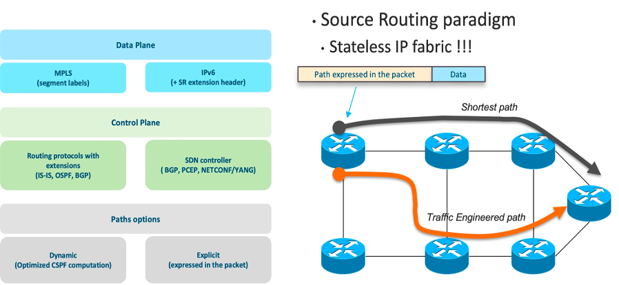 Segment Routing Architecture Overview
Figure 1 - Segment Routing Architecture Overview
Why SRv6?
IPv6 is the new normal and SRv6 is a new paradigm for logical progression towards SDN and the programmable network. SRv6 was conceived to bridge the gap between SDN and traditional networking. SRv6 provides advanced SRv6 Traffic Engineering (TE) capabilities, transforms the network into a multi-service infrastructure, and Flexible Algorithm (Flex-Algo or FA) capabilities in order to enable multiple optimizations of the same physical network infrastructure along various dimensions.
Simplification
SRv6 eliminates the need to tunnel technologies such as LDP and RSVP-TE through an extension of IGP and simplifies the control plane. It uses an IPv6 address in order to program the end-to-end path instead of the use of an MPLS label on the data plane. SRv6 greatly simplifies network protocols and reduces the complexity of operation and maintenance at the Control plane and data plane levels. It allows the cloud, network, and terminals to implement an end-to-end manageable and controllable solution based on the same standard protocol.
Additionally, because the shortest path segment includes all the ECMP paths to the related node, SR supports the ECMP nature of IP by design.
Native IPv6 Attribute
SRv6 allows a node to steer a packet through the SR domain with the use of an ordered list of segments and instructs how nodes along the path can process the packet. Segments in SRv6 can refer to the instruction to send a packet over the shortest path to a node, over a specific link, or towards an application. SRv6 is source-based routing, path information is encoded in the packet that it must traverse, and intermediate routers do not have to maintain state for all paths. SRv6 empowers to break the boundary between the operator network and the data center network, which greatly enhances the extensibility and deployment flexibility of SRv6.
Network Programming Capabilities
The infrastructure programming capability of SRv6 is a game-changer in the way the network treats applications. The network is no longer merely routing traffic from point A to point B as per some specific constraints expressed by applications (for example, SR traffic engineering). The network can now take actions on the applications along the same path applications are transported over. It makes your applications and your network interact in a completely different, new way.
Traffic Engineering
Leveraging the most advanced SRv6 traffic engineering capabilities, the network can be turned into a multi-service infrastructure. New Flexible Algorithm capabilities make multiple optimizations of the same physical network infrastructure along various dimensions possible (for example, one can be optimized for low latency versus another one for bandwidth, or one can offer disjoint paths via two distinct planes)
Network slicing plays a major role as service providers and enterprises get ready to offer a wide range of 5G services, that have specific and differentiated needs, over a converged infrastructure. As a result, service providers implement top-notch traffic engineering solutions across their network, directly from the cell site and up to the core and data centers, in order to ensure each service gets its own dedicated networking slice with its own set of SLAs.
Resiliency
Resiliency plays a pivotal role in order to ensure the network stays up always so that you can access their services from anywhere at any time. Current IGP routing protocols provide a first level of resiliency by rerouting traffic around failures in the network. But it is not enough. More and more applications need the network to guarantee under 50 ms protection against any kind of network failure. This is exactly what SRv6 TI-LFA (Topology Independent Loop Free Alternate) with Uloop avoidance brings with 100% topology coverage, simplicity. and path optimality.
SRv6 Services
In SRv6-based services, the egress PE signals an SRv6 Service SID with the BGP service route. The ingress PE encapsulates the payload in an outer IPv6 header where the destination address is the SRv6 Service SID advertised by the egress PE. BGP messages between PEs carry SRv6 Service SIDs in order to interconnect PEs and form VPNs. SRv6 Service SID refers to a segment identifier associated with one of the SRv6 service-specific behaviors advertised by the egress PE router, such as:
- uDT4 (Endpoint with decapsulation and IPv4 table lookup)
- uDT6 (Endpoint with decapsulation and IPv6 table lookup)
- uDX4 (Endpoint with decapsulation and IPv4 cross-connect)
- uDX6 (Endpoint with decapsulation and IPv6 cross-connect)
These SRv6-based services are supported at the time of writing:
- Layer-3 BGP-based services –L3VPN
- Layer-2 BGP-based services -EVPN-VPWS
L3VPN
The SRv6-based L3VPN feature enables the deployment of L3VPN over an SRv6 data plane. SRv6-based L3VPN uses SRv6 Segment IDs (SIDs) for service segments instead of labels.
The BGP SID can be allocated in these ways:
- Per-VRF mode that provides uDT4 or uDT6 support. uDT4/uDT6 represents the Endpoint with decapsulation and IPv4 or IPv6 table lookup. uDT4 and uDT6 is used for IPv4 L3VPN and IPv6 L3VPN respectively.
- Per-CE mode that provides uDX4 and uDX6 cross-connect support. uDX4 represents the Endpoint with decapsulation and IPv4 cross-connect. Similarly, uDX6 represents the Endpoint with decapsulation and IPv6 cross-connect.
EVPN VPWS
EVPN VPWS uses a BGP control plane for point-to-point services. The advantages of VPWS with EVPN are:
- Eliminates the need to signal pseudowire services for point-to-point Ethernet services
- Multi-homing capabilities like single-active/active-active/port-active
uDX2 SID endpoint behavior is used for EVPN VPWS services.
SRv6 Use-Cases
Service Function Chaining
Service Function Chaining (SFC) enables the creation of composite network services that consists of an ordered set of service functions. SFC denotes the process of forwarding packets through the sequence of Virtual Network Functions (VNFs). SRv6 provides a simple and scalable way to chain service functions for both SR-aware service and SR-unaware service functions (SF). SRv6 is a source routing paradigm that allows you to steer packets through an ordered list of VNFs. SR enables SFC through the allocation of a SID to each SF and the sequencing of these SF SIDs in a SID list. If SF is SRv6 unaware, an SR proxy is needed in front of the SF to route the traffic to that SF.
SFC is one of the essential functions in data centers. Traffic in data centers passes through various functions like firewalls, Intrusion Detection Systems (IDS), Deep Packet Inspection (DPI), and Network Address Translation (NAT) that process packets and thus form a chain of services. Hence the name service function chaining or service chaining.
Slicing
SRv6 helps to create SLA constraints-based slices that start right from the user application all the way through the transport to the central data center. The logical separation with slicing with SRv6 traffic engineering and flexible algorithm helps to provide specific service treatment for latency-sensitive applications with bandwidth optimization. Network slicing plays a major role as service providers and enterprises get ready to offer a wide range of 5G services.
Load Balancing
The SRv6 solution provides day-1 optimum load-balancing contrary to MPLS, which still has issues with load balancing. In MPLS, the entropy for Equal-Cost Multi-Path (ECMP) selection is in the inner IP packet, so the routers must dig down through the MPLS label stack in order to get access to the IP header used for hashing.
In SRv6, the Ingress PE computes a hash on the customer packet and writes the result in the Flow Label field of the added outer IPv6 header. The rest of the network leverages this Flow Label in order to perform ECMP selection with just a look at the outer header with no need to dig down through the layers of encapsulation.
Operations and Performance Management
Path Tracing functionality helps to provide operations and performance management of SRv6 transport with the provision of a record of the packet path as a sequence of interface IDS. In addition, it provides a record of end-to-end delay, per-hop delay, and load on each egress interface along the packet delivery path. Path Tracing allows you to trace 14 hops with only a 40-byte IPv6 Hop-by-Hop extension header.
It supports fine-grained timestamps and has been designed for line rate hardware implementation in the base pipeline.
For more details, refer to SRv6 Technology Basics.
Design Guidelines and Best Practices
Locator Planning
As the name suggests, SRv6 is the segment routing deployed over the IPv6 data plane. Therefore, in order to enable Segment routing over v6, Service provider infrastructure must be enabled first for IPv6. Hence, the first step to deploy SRv6 is to plan the address space for IPv6 deployment. During the planning phase, one of the subnets can be selected for SRv6 locator addresses. In SRv6, a SID represents a 128-bit value, out of which the locator is the first part of the service SID with the most significant bits, used for routing to the node which is responsible to perform the function as explained in this section. You can also think of this as a network address.
RFC8986 defines an SRv6 service SID as consisting of three parts:
- LOCATOR: This part serves as the reachability information for the node that allocates the SID and is globally known and routable. In an F3216 uSID format, the locator portion is the 48-bit uN.
- FUNCTION: This is significant to the owning node only. Designates a specific SRv6 End function. In an F3216 uSID, this is a 16-bit locally scoped uSID.
- ARGS: Optional arguments to the function.
SRv6 locator SIDs to a node can be assigned independently from the IPv6 addressing of that node. For an SRv6 network, IPv6 addresses can be planned for infrastructure addresses, management planes, and service addresses for overlay end users. Infrastructure IP addressing and SRv6 SID allocation can belong to two different blocks; for example, infrastructure IPv6 addresses such as network addresses for device interconnections are allocated from an IPv6 address block planned for infrastructure addresses or management plane and SRv6 SIDs are allocated from the block planned for service plane.
Though infrastructure addresses and SIDs are represented as IPv6 addresses, both are recommended to be allocated from different blocks. This way an IPv6 address plan that exists is not a constraint for any current or future SRv6 SID allocation plan.
For the SRv6 uSID carrier, the format is generally specified with the notation 'Fbbuu', where 'bb' is the size of the block and 'uu' is the size of the ID. For example, 'F3216' is a format with a 32-bit uSID block and 16-bit uSID IDs. In order to align with this, the general addressing strategy can comply with a four-tier locator structure: SID Space, uSID Block, Set ID, and Node lD as explained here:
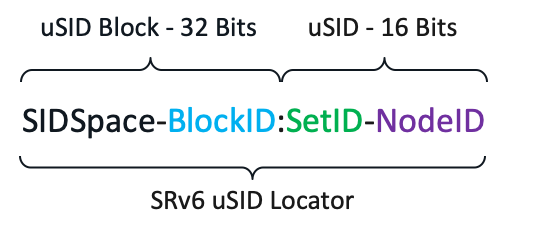 uSID format
Figure 2 - uSID format
The first two tiers are formed from the uSID block:
- SID Space: The IPv6 address block is used to allocate the SID locator. All SID Blocks in the network must come from the same 24-bit SID space.
- Block ID: Common prefix of a block of uSIDs. Its size depends on the uSID format, which is 8-bit in uSID format
The next two tiers are formed from the uSID ID:
- Set IDs: Any group of uSIDs that share a certain value for the first two nibbles of the ID. A 16-bit uSID space contains 256 sets. Each set represents 256 uSID values. A set is uniquely bound to an algorithm.
- Node ID: Global node SID, Adjacency SID or IP overlay service SID.
'It is a recommended best practice that SRv6 SIDs for locators are allocated from the private IPv6 Unique Local Address (ULA) address range which starts with FC00:. A sub-range of /24 can be used from IPv6 ULA address space like FC00::/8. The public range for SID space is supported as well, hence, the SID block can be allocated from globally allocated blocks as well. This figure indicates the recommended locator allocation logic that can be used during the planning and design phase. Bits allocation for ‘SSNN’ under uSID1 can be tweaked as per the requirement by the provider and does not have to end at the 8-bit boundary as shown for Nibble 33-40.
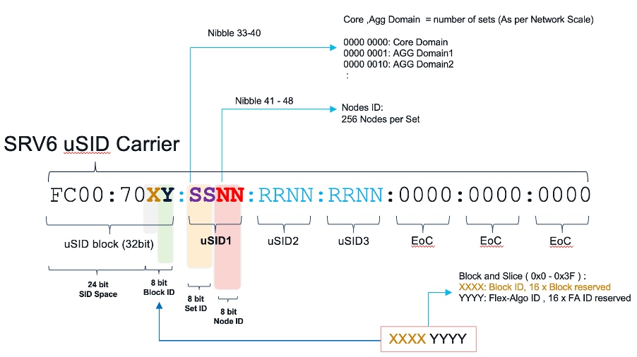 uSID Locator Planning Example
Figure 3 - uSID Locator Planning Example
- SID Space: First 24 bits of the uSID constitute the base SID space. As stated, it is recommended to use a private block for the uSID in a deployment.
- Block ID: The next 8 bits on the uSID block constitute the block ID which can be split into X and Y where X can denote a slice or a block whereas Y denotes the flex-algo IDs.
- Set ID: 8 bits from the uSID ID denote the set ID. Set IDs can be reserved based on geographical area and density.
- Node ID: Least significant 8 bits represent node ID. A total of 255 nodes can be assigned with a locator.
For different flex-algorithm, it is recommended to use different locator schemas which can be derived with the method explained.
Loopback Address Planning
In the SRv6 deployment, the loopback address can be allocated from the locator prefix range or independently from the planned infrastructure IPv6 range as well. However, if the loopback address is allocated from the locator prefix range then it is reachable via the locator prefix range announcement itself and does not have to be separately advertised as a /128 prefix between the domains.
For example, if the uSID locator block is BBBB:BB00:0001/48 then the loopback address can be BBBB:BB00:0001::L /128 with L=1-F. IGP ISIS takes care to advertise the locator block so there is no need to advertise the loopback block separately.

Note: Dynamic SIDs do not conflict with SIDs/prefixes that exist, like loopback addresses from the locator block.
Advantages of Loopback Addressing from Locator Block
There are several advantages to allocate loopback addressing from the locator block:
- No additional IGP prefixes help in improved scale
- No additional FIB entries help in improved Hardware scale
- No additional address allocation effort
- No additional redistribution/leaking/summarizations which results in lesser operational complexity
- Validation of locator reachability with ping is not required
- Easier to apply separate security treatment to services traffic (and its ICMP error messages)
- BGP NH and SID share fate
When you have the loopbacks IP schema from locator space, it results in SA and DA of services traffic in the SRv6 space as SRv6 applications (like ISIS, BGP) use it in order to allocate SIDs.
The loopback for BGP peering can be carved out from the locator set taken from the services block. With the loopback addresses carved out of the service block with the redistribution of a locator block at the aggregation node or border node, Loopbacks under a locator are reachable via the locator prefix and do not have to be advertised separately as a /128 prefix.
Prefix Summarization
SRv6 prefix summarization is an inherent benefit to IP networks. SRv6 gets rid of all these complexities of MPLS where the advertising /32 prefix was a requirement for the data plane to function. Whereas with SRv6; if you have two metro networks, each with hundreds of thousands of /64 locators (SRv6 capable routers), a single summary route can be advertised into the core by each metro. So, the core only carries the locators of the core nodes and the summary routes of the metro networks. This is an extremely powerful feature in terms of simplicity and scalability.
 Locator Summarization
Figure 4 - Locator Summarization
Quick Comparison between SRv6 and MPLS/SR-MPLS
IP Route Aggregation
MPLS/SR-MPLS: Label binding with a 32-bit host address has to be advertised across multiple domains without aggregation. Lack of route summarization has a scalability impact on large-scale Service Providers.
SRv6: Inherit native IP feature and aggregated routed can be imported across network domains which has a significant advantage in terms of simplicity and scalability for the operators.
End-to-end Service Auto-start
SR-MPLS: SRGB and Node SID need overall network-wide planning in the cross-domain scenario.
SRv6: With SRv6, the operator can set up an E2E tunnel directly based on just plain IPv6 reachability. SRv6 support on the transient node is not mandatory, hence, operators have the flexibility to enable SRv6 in a phased manner, whereas, in the case of MPLS, end-to-end MPLS data plane support is required.
On-Demand Upgrade
SR-MPLS: Upgrade the entire network first and then deploy the SR-MPLS, or deploy mapping servers at some of the intermediate nodes.
SRv6: The network can be migrated to SRv6 on demand. As highlighted earlier, the nodes where SRv6 is not enabled or supported can be traversed through normal IPv6 forwarding.
In summary:
MPLS/SR-MPLS: IP reachability is the base. MPLS label advertisement must be done in the whole network.
SRv6: IPv6 reachability is the base. SRv6 can be deployed incrementally, in a phased manner.
SRv6 - High-Level Migration Strategy
 High-Level Migration Strategy
Figure 5 - High-Level Migration Strategy
For a smoother migration, it is recommended to proceed with an incremental phase-wise approach. At a high level, this is the incremental deployment approach:
- First, configure the IPv6 address for the infrastructure and enable IGP in order to advertise these addresses.
- Choose a set of PE devices to be configured with SRv6 and move overlay services in a phased manner.
It is recommended to have a separate BGP route reflector for SRv6 because multiple address families (IPv6, VPNv4, VPNv6, and so on) have to be configured. For the SRv6 enablement, IPv6 must be enabled in the network.
Step 1. Upgrade to IPv6 (IPv6 ready is the pre-condition of SRv6)
Step 2. Upgrade the edge devices in order to introduce VPN over SRv6 PE
Step 3. Upgrade some intermediate nodes in order to support traffic TI-LFA, TE, SFC, and so on
Step 4: Upgrade the whole network in order to support E2E SRv6
Service Migration from MPLS/SR-MPLS
For a smoother migration, it is recommended to proceed with an incremental phase-wise approach. At a high level, this is the incremental deployment approach:
- First, configure the IPv6 address for the infrastructure and enable IGP in order to advertise these addresses.
- Choose a set of PE devices to be configured with SRv6 and move overlay services in a phased manner.
It is recommended to have a separate BGP route reflector for SRv6. BGP has been enhanced and provided support to extended services over an SRv6 network, such as:
- IPv4 Layer-3 VPNs
- IPv6 Layer-3 VPNs
- IPv4 BGP global
- IPv6 BGP global
- Layer-2 VPNs - Ethernet VPNs (EVPN)
Based on the messages and procedures defined in the IETF draft 'SRv6 BGP based Overlay services', BGP encodes the SRv6 Service SID in the prefix-SID attribute of the BGP Network Layer Reachability Information (NLRI) that corresponds and advertises it to its IPv6 BGP peers.
L3VPN
The SRv6-based L3VPN feature enables the deployment of L3VPN over an SRv6 data plane. In SRv6-based services, the egress PE signals an SRv6 Service SID with the BGP service route. The ingress PE encapsulates the payload in an outer IPv6 header where the destination address is the SRv6 Service SID advertised by the egress PE. BGP messages between PEs carry SRv6 Service SIDs as a means to interconnect PEs and form VPNs. SRv6 Service SID refers to a segment identifier associated with one of the SRv6 service-specific behaviors advertised by the egress PE router, such as:
- uDT4 (Endpoint with decapsulation and IPv4 table lookup)
- uDT6 (Endpoint with decapsulation and IPv6 table lookup)
EVPN Multi-homing
This feature provides an ELINE (P2P) service with all-active multihoming capability over an SRv6 network. All-Active Multi-Homing enables an operator in order to connect a customer edge (CE) device to two or more provider edge (PE) devices in order to provide load balancing and redundant connectivity. With All-Active Multi-Homing, all the PEs can forward traffic to and from the multi-homed device. These uSID functions are used:
- uDX4 (Endpoint with decapsulation and IPv4 cross-connect)
- uDX6 (Endpoint with decapsulation and IPv6 cross-connect)
SRv6 Interworking Gateway
SRv6/MPLS L3 Service Interworking Gateway enables you to extend L3 services between MPLS and SRv6 domains by providing service continuity on the control plane and data plane.
This feature allows for SRv6 L3VPN domains to interwork with the MPLS L3VPN domains that exist. The feature also allows a way to migrate from MPLS L3VPN to SRv6 L3VPN.
The SRv6/MPLS L3 Service Interworking Gateway provides both transport and service termination at the gateway node. The gateway generates both SRv6 VPN SIDs and MPLS VPN labels for all prefixes under the VRF configured for re-origination. The gateway supports traffic forwarding from the MPLS domain to the SRv6 domain by popping the MPLS VPN label, looking up the destination prefix, and pushing the appropriate SRv6 encapsulation. From the SRv6 domain to the MPLS domain, the gateway removes the outer IPv6 header, looks up the destination prefix, and pushes the VPN and next-hop MPLS labels.
VRFs on the gateway node are configured with two sets of route targets (RTs):
- MPLS L3VPN RTs
- SRv6 L3VPN RTs (called stitching RTs)
The gateway performs these actions:
- Imports service routes received from one domain (MPLS or SRv6)
- Re-advertises exported service routes to the other domain (next-hop-self)
- Stitches the service on the data plane (uDT4/H.Encaps.Red ↔ service label)
Migration Approach and Guidelines
Migration from an LDP-based MPLS network or SR-based MPLS network is quite similar. On Day 0, every node in the network runs MPLS, be it LDP or SR based, in the underlying data plane for all the services a Telco Service Provider provides. This is a sample lab topology used in order to explain the phased migration approach.
 Day 0 Network State
Figure 6 - Day 0 Network State
In order to enable Segment Routing over IPv6, use the hw-module profile segment-routing srv6 mode micro-segment format f3216command in XR Configuration mode. This command is applicable only for Cisco IOS XR-based devices.
In order to prepare the network for SRv6 migration, first, an operator must plan for IPv6 enablement in the network. As stated earlier without IPv6, SRv6 cannot be enabled. So with planned IPv6 addresses for infrastructure, IPv6 must be enabled everywhere in the network. In the first phase of the migration, all logical and physical interfaces on the node get an IPv6 address. This is in addition to the IPv4 address (dual-stack approach) that exists. This way all the services continue to run over the data plane that exists.
Once IPv6 addresses are configured in the SP infrastructure on interfaces as well as loopback, IGP must be enabled in order to advertise the IPv6 prefixes in the domain.
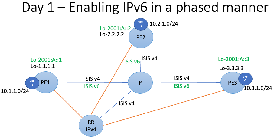 Day 1 Network State
Figure 7 - Day 1 Network State
Here are the steps taken for ISIS:
- Configure IGP-ISIS for IPv6:
IGP is configured in a network for devices within the network in order to reach each other. You must configure IS-IS for the IPv6 address family.
router isis 100

 address-family ipv6 unicast

  !

 !

!

 interface Loopback0

  address-family ipv6 unicast

! !

 interface GigabitEthernet0/0/0/1

  address-family ipv6 unicast

  !

 !

 interface GigabitEthernet0/0/0/2

  address-family ipv6 unicast

  !

 !

!

Commit
ISIS IPv6 Address-family enablement can be done in a phased manner. Once the devices have reachability over IPv6, you must proceed with BGP.
On day 2, as a next step for SRv6 enablement, it is recommended to have a separate set of BGP Route-reflector and these route-reflectors are for multiple address families (IPv6, VPNv4, VPNv6, and so on). This way the route reflector that exists is not disturbed. Note that all Telco Services run on the MPLS data plane that exists at this stage.
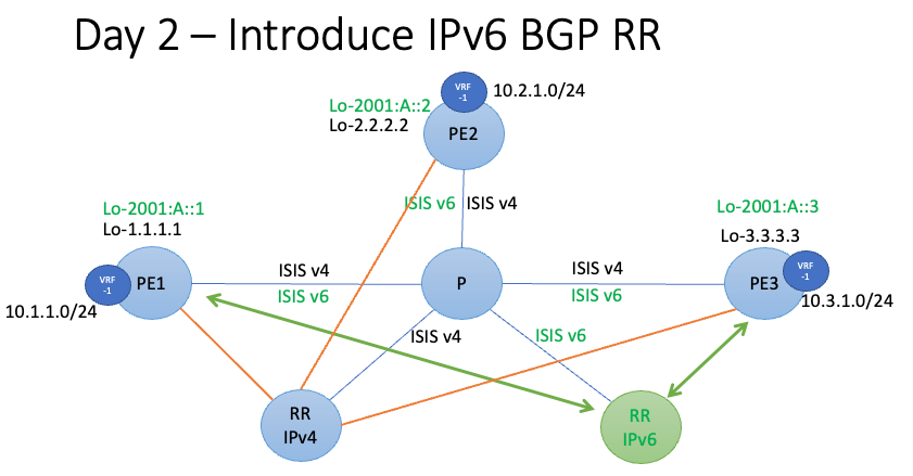 Day 2 Network State
Figure 8 - Day 2 Network State
This configuration snippet highlights BGP configuration.
- Configure BGP for IPV6:
Configure BGP for the IPv6 address family.
!

!

route-policy LOCAL-PREF

 set local-preference 50

 end-policy

!

commit

!

!

router bgp 100

 !

 neighbor 2001:db8:2:2:2::2

  remote-as 100

  update-source Loopback0

  address-family vpnv4 unicast

   route-policy LOCAL-PREF in

  !

commit
A local preference of 50 in BGP is added as currently. You want the routes via MPLS RR to be preferred so the services run fine.
Now for the SRv6 migration, you can take a very safe incremental approach and start with just two PEs.
Then, the SRv6 locator under segment routing must be considered and this must be advertised via IGP and BGP for services.
 Day 3 Network State
Figure 9 - Day 3 Network State
- Configure SRv6:
This section describes how to configure SRv6.
router isis 100

 address-family ipv6 unicast

  segment-routing srv6

   locator LOC0

!

router bgp 100

!

 segment-routing srv6

  locator LOC0

 !

vrf XYZ

  address-family ipv4 unicast

   segment-routing srv6

    alloc mode per-vrf

   !

  !

!

segment-routing

 srv6

  locators

   locator LOC0

   prefix 2001:db8:a::/48

commit
You can change the local preference for the routes that come from SRv6 RR and make them preferred VPN routes. This way just between these two PEs, L3VPN VRF traffic flows over SRv6.
Slowly, other PEs and services can be migrated with a similar approach. Once all the PEs are migrated to SRv6, the IPv4 MPLS RR and the associated configuration can be taken down from the network.
Related Information
Revision History
| Revision | Publish Date | Comments |
|---|---|---|
1.0 |
01-Jun-2023 |
Initial Release |
Contributed by Cisco Engineers
- Ramakrishnan ShanmugasundaramCustomer Delivery Architect
- Sunil PareekCustomer Delivery Architect
- Satya Priyo DharCustomer Delivery Architect
Contact Cisco
- Open a Support Case

- (Requires a Cisco Service Contract)
 Feedback