IEEE 802.1x Multi-Domain Authentication on Cisco Catalyst Layer 3 Fixed Configuration Switches Configuration Example
Available Languages
Contents
Introduction
Multi-Domain Authentication allows an IP Phone and a PC to authenticate on the same switch port while it places them on appropriate Voice and Data VLANs. This document explains how to configure IEEE 802.1x Multi-Domain Authentication (MDA) on Cisco Catalyst Layer 3 fixed configuration switches.
Prerequisites
Requirements
Ensure that you meet these requirements before you attempt this configuration:
Components Used
The information in this document is based on these software and hardware versions:
-
Cisco Catalyst 3560 Series Switch that runs Cisco IOS® Software Release 12.2(37)SE1
Note: Multi-Domain Authentication support is available only from Cisco IOS Software Release 12.2(35)SE and later.
-
This example uses Cisco Secure Access Control Server (ACS) 4.1 as the RADIUS server.
Note: A RADIUS server must be specified before you enable 802.1x on the switch.
-
PC clients that supports 802.1x authentication
Note: This example uses Microsoft Windows XP clients.
-
Cisco Unified IP Phone 7970G with SCCP firmware version 8.2(1)
-
Cisco Unified IP Phone 7961G with SCCP firmware version 8.2(2)
-
Media Covergence Server (MCS) with Cisco Unified Communications Manager (Cisco CallManager) 4.1(3)sr2
The information in this document was created from the devices in a specific lab environment. All of the devices used in this document started with a cleared (default) configuration. If your network is live, make sure that you understand the potential impact of any command.
Related Products
This configuration can also be used with these hardwares:
-
Cisco Catalyst 3560-E Series Switch
-
Cisco Catalyst 3750 Series Switch
-
Cisco Catalyst 3750-E Series Switch
Note: Cisco Catalyst 3550 Series Switch does not support 802.1x Multi-Domain Authentication.
Conventions
Refer to Cisco Technical Tips Conventions for more information on document conventions.
Background Information
The IEEE 802.1x standard defines a client-server based access control and authentication protocol that restricts unauthorized devices from connecting to a LAN through publicly accessible ports. 802.1x controls network access by the creation of two distinct virtual access points at each port. One access point is an uncontrolled port; the other is a controlled port. All traffic through the single port is available to both access points. 802.1x authenticates each user device that is connected to a switch port and assigns the port to a VLAN before it makes available any services that are offered by the switch or the LAN. Until the device is authenticated, 802.1x access control allows only Extensible Authentication Protocol over LAN (EAPOL) traffic through the port to which the device is connected. After authentication is successful, normal traffic can pass through the port.
802.1x is comprised of three primary components. Each is referred to as a Port Access Entity (PAE).
-
Supplicant—Client device that requests network access, for example, IP Phones and attached PCs
-
Authenticator—Network device that facilitates the Supplicant authorization requests, for example, Cisco Catalyst 3560
-
Authentication Server—A Remote Authentication Dial-in User Server (RADIUS), which provides the authentication service, for example, Cisco Secure Access Control Server
The Cisco Unified IP phones also contain an 802.1X supplicant. This supplicant allows network administrators to control the connectivity of IP Phones to the LAN switch ports. The initial release of the IP phone 802.1X supplicant implements the EAP-MD5 option for 802.1X authentication. In a multi-domain configuration, the IP Phone and the attached PC must independently request access to the network by the specification of a username and password. The Authenticator device can require information from the RADIUS called attributes. Attributes specify additional authorization information such as whether access to a particular VLAN is allowed for a Supplicant. These attributes can be vendor specific. Cisco uses the RADIUS attribute cisco-av-pair in order to tell the Authenticator (Cisco Catalyst 3560) that a Supplicant (IP Phone) is allowed on the voice VLAN.
Configure
In this section, you are presented with the information to configure the 802.1x multi-domain authentication feature described in this document.
This configuration requires these steps:
Note: Use the Command Lookup Tool (registered customers only) in order to find more information on the commands used in this document.
Network Diagram
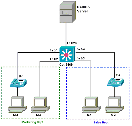
This document uses this network setup:
-
RADIUS server—This performs the actual authentication of the client. The RADIUS server validates the identity of the client and notifies the switch whether or not the client is authorized to access the LAN and switch services. Here, the Cisco ACS is installed and configured on a Media Covergence Server (MCS) for authentication and VLAN assignment. The MCS is also the TFTP server and Cisco Unified Communications Manager (Cisco CallManager) for the IP Phones.
-
Switch—This controls the physical access to the network based on the authentication status of the client. The switch acts as an intermediary (proxy) between the client and the RADIUS server. It requests identity information from the client, verifies that information with the RADIUS server, and relays a response to the client. Here, the Catalyst 3560 switch is also configured as a DHCP server. The 802.1x authentication support for the Dynamic Host Configuration Protocol (DHCP) allows the DHCP server to assign the IP addresses to the different classes of end users. In order to do this, it adds the authenticated user identity into the DHCP discovery process. Ports FastEthernet 0/1 and 0/4 are the only ports configured for 802.1x multi-domain authentication. Ports FastEthernet 0/2 and 0/3 are in the default 802.1x single host mode. Port FastEthernet 0/24 connects to the RADIUS server.
Note: If you use an external DHCP server, do not forget to add the ip helper-address command on the SVI (vlan) interface, in which the client resides, which points to the DHCP server.
-
Clients—These are devices, for example, IP Phones or Workstations, that request access to the LAN and switch services and respond to requests from the switch. Here, clients are configured in order to attain the IP address from a DHCP server. Devices M-1, M-2, S-1 and S-2 are the workstation clients that request access to the network. P-1 and P-2 are the IP Phone clients that request access to the network. M-1, M-2 and P-1 are client devices in the marketing department. S-1, S-2 and P-2 are client devices in the sales department. IP Phones P-1 and P-2 are configured to be in the same voice VLAN (VLAN 3). Workstations M-1 and M-2 are configured to be in the same data VLAN (VLAN 4) after a successful authentication. Workstations S-1 and S-2 are also configured to be in the same data VLAN (VLAN 5) after a successful authentication.
Note: You can use dynamic VLAN assignment from a RADIUS server only for the data devices.
Configure the Catalyst Switch for 802.1x Multi-Domain Authentication
This sample switch configuration includes:
-
How to enable 802.1x multi-domain authentication on the switch ports
-
RADIUS server related configuration
-
DHCP server configuration for IP address assignment
-
Inter-VLAN routing to have connectivity between clients after authentication
Refer to Using Multidomain Authentication for more information about the guidelines on how to configure MDA.
Note: Make sure that the RADIUS server always connects behind an authorized port.
Note: Only the relevant configuration is shown here.
| Cat-3560 |
|---|
Switch#configure terminal
Switch(config)#hostname Cat-3560

!--- Sets the hostname for the switch.

Cat-3560(config)#vlan 2
Cat-3560(config-vlan)#name SERVER
Cat-3560(config-vlan)#vlan 3
Cat-3560(config-vlan)#name VOICE
Cat-3560(config-vlan)#vlan 4
Cat-3560(config-vlan)#name MARKETING
Cat-3560(config-vlan)#vlan 5
Cat-3560(config-vlan)#name SALES
Cat-3560(config-vlan)#vlan 6
Cat-3560(config-vlan)#name GUEST_and_AUTHFAIL

!--- VLAN should already exist in the switch for a successful authentication.

Cat-3560(config-vlan)#exit
Cat-3560(config)#interface vlan 2
Cat-3560(config-if)#ip address 172.16.2.1 255.255.255.0
Cat-3560(config-if)#no shut

!--- This is the gateway address for the RADIUS Server.

Cat-3560(config-if)#interface vlan 3
Cat-3560(config-if)#ip address 172.16.3.1 255.255.255.0
Cat-3560(config-if)#no shut

!--- This is the gateway address for IP Phone clients in VLAN 3.

Cat-3560(config-if)#interface vlan 4
Cat-3560(config-if)#ip address 172.16.4.1 255.255.255.0
Cat-3560(config-if)#no shut

!--- This is the gateway address for PC clients in VLAN 4.

Cat-3560(config-if)#interface vlan 5
Cat-3560(config-if)#ip address 172.16.5.1 255.255.255.0
Cat-3560(config-if)#no shut

!--- This is the gateway address for PC clients in VLAN 5.

Cat-3560(config-if)#exit
Cat-3560(config)#ip routing

!--- Enables IP routing for interVLAN routing.

Cat-3560(config)#interface range fastEthernet 0/1 - 4
Cat-3560(config-if-range)#shut
Cat-3560(config-if-range)#exit
Cat-3560(config)#interface fastEthernet 0/24
Cat-3560(config-if)#switchport mode access
Cat-3560(config-if)#switchport access vlan 2

!--- This is a dedicated VLAN for the RADIUS server.

Cat-3560(config-if)#spanning-tree portfast
Cat-3560(config-if)#exit
Cat-3560(config)#interface range fastEthernet 0/1 , fastEthernet 0/4
Cat-3560(config-if-range)#switchport mode access
Cat-3560(config-if-range)#switchport voice vlan 3

!--- You must configure the voice VLAN for the IP phone when the !--- host mode is set to multidomain. !--- Note: If you use a dynamic VLAN in order to assign a voice VLAN !--- on an MDA-enabled switch port, the voice device fails authorization.

Cat-3560(config-if-range)#dot1x port-control auto

!--- Enables IEEE 802.1x authentication on the port.

Cat-3560(config-if-range)#dot1x host-mode multi-domain

!--- Allow both a host and a voice device to be !--- authenticated on an IEEE 802.1x-authorized port.

Cat-3560(config-if-range)#dot1x guest-vlan 6
Cat-3560(config-if-range)#dot1x auth-fail vlan 6

!--- The guest VLAN and restricted VLAN features only apply to the data devices !--- on an MDA enabled port.

Cat-3560(config-if-range)#dot1x reauthentication

!--- Enables periodic re-authentication of the client.

Cat-3560(config-if-range)#dot1x timeout reauth-period 60

!--- Set the number of seconds between re-authentication attempts.

Cat-3560(config-if-range)#dot1x auth-fail max-attempts 2

!--- Specifies the number of authentication attempts to allow !--- before a port moves to the restricted VLAN.

Cat-3560(config-if-range)#exit
Cat-3560(config)#interface range fastEthernet 0/2 - 3
Cat-3560(config-if-range)#switchport mode access
Cat-3560(config-if-range)#dot1x port-control auto

!--- By default a 802.1x authorized port allows only a single client.

Cat-3560(config-if-range)#dot1x guest-vlan 6
Cat-3560(config-if-range)#dot1x auth-fail vlan 6
Cat-3560(config-if-range)#dot1x reauthentication
Cat-3560(config-if-range)#dot1x timeout reauth-period 60
Cat-3560(config-if-range)#dot1x auth-fail max-attempts 2
Cat-3560(config-if-range)#spanning-tree portfast
Cat-3560(config)#ip dhcp pool IP-Phones
Cat-3560(dhcp-config)#network 172.16.3.0 255.255.255.0
Cat-3560(dhcp-config)#default-router 172.16.3.1
Cat-3560(dhcp-config)#option 150 ip 172.16.2.201

!--- This pool assigns ip address for IP Phones. !--- Option 150 is for the TFTP server.

Cat-3560(dhcp-config)#ip dhcp pool Marketing
Cat-3560(dhcp-config)#network 172.16.4.0 255.255.255.0
Cat-3560(dhcp-config)#default-router 172.16.4.1

!--- This pool assigns ip address for PC clients in Marketing Dept.

Cat-3560(dhcp-config)#ip dhcp pool Sales
Cat-3560(dhcp-config)#network 172.16.5.0 255.255.255.0
Cat-3560(dhcp-config)#default-router 172.16.5.1

!--- This pool assigns ip address for PC clients in Sales Dept.

Cat-3560(dhcp-config)#exit
Cat-3560(config)#ip dhcp excluded-address 172.16.3.1
Cat-3560(config)#ip dhcp excluded-address 172.16.4.1
Cat-3560(config)#ip dhcp excluded-address 172.16.5.1
Cat-3560(config)#aaa new-model
Cat-3560(config)#aaa authentication dot1x default group radius

!--- Method list should be default. Otherwise dot1x does not work.

Cat-3560(config)#aaa authorization network default group radius

!--- You need authorization for dynamic VLAN assignment to work with RADIUS.

Cat-3560(config)#radius-server host 172.16.2.201 key CisCo123

!--- The key must match the key used on the RADIUS server.

Cat-3560(config)#dot1x system-auth-control

!--- Globally enables 802.1x.

Cat-3560(config)#interface range fastEthernet 0/1 - 4
Cat-3560(config-if-range)#no shut
Cat-3560(config-if-range)#^Z
Cat-3560#show vlan

VLAN Name                             Status    Ports
---- -------------------------------- --------- -------------------------------
1    default                          active    Fa0/1, Fa0/2, Fa0/3, Fa0/4
                                                Fa0/5, Fa0/6, Fa0/7, Fa0/8
                                                Fa0/9, Fa0/10, Fa0/11, Fa0/12
                                                Fa0/13, Fa0/14, Fa0/15, Fa0/16
                                                Fa0/17, Fa0/18, Fa0/19, Fa0/20
                                                Fa0/21, Fa0/22, Fa0/23, Gi0/1
                                                Gi0/2
2    SERVER                           active    Fa0/24
3    VOICE                            active    Fa0/1, Fa0/4
4    MARKETING                        active
5    SALES                            active
6    GUEST_and_AUTHFAIL               active
1002 fddi-default                     act/unsup
1003 token-ring-default               act/unsup
1004 fddinet-default                  act/unsup
1005 trnet-default act/unsup |
Note: Use the Command Lookup Tool (registered customers only) in order to obtain more information on the commands used in this section.
Configure the RADIUS Server
The RADIUS server is configured with a static IP address of 172.16.2.201/24. Complete these steps in order to configure the RADIUS server for an AAA client:
-
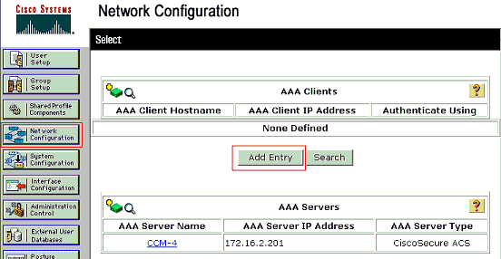
Click Network Configuration on the ACS administration window in order to configure an AAA client.
-
Click Add Entry under the AAA clients section.
-
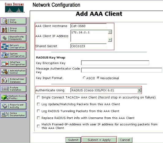
Configure the AAA client hostname, IP address, shared secret key and authentication type as:
-
AAA client hostname = Switch Hostname (Cat-3560).
-
AAA client IP address = Management interface IP address of the switch (172.16.2.1).
-
Shared Secret = RADIUS Key configured on the switch (CisCo123).
Note: For correct operation, the shared secret key must be identical on the AAA client and ACS. Keys are case sensitive.
-
Authenticate Using = RADIUS (Cisco IOS/PIX 6.0).
Note: Cisco Attribute-Value (AV) pair attribute is available under this option.
-
-
Click Submit + Apply in order to make these changes effective, as this example shows:
Group Setup
Refer to this table in order to configure the RADIUS server for authentication.
| Device | Dept | Group | User | Password | VLAN | DHCP Pool |
|---|---|---|---|---|---|---|
| M-1 | Marketing | Marketing | mkt-manager | MMcisco | MARKETING | Marketing |
| M-2 | Marketing | Marketing | mkt-staff | MScisco | MARKETING | Marketing |
| S-2 | Sales | Sales | sales-manager | SMcisco | SALES | Sales |
| S-1 | Sales | Sales | sales-staff | SScisco | SALES | Sales |
| P-1 | Marketing | IP Phones | CP-7970G-SEP001759E7492C | P1cisco | VOICE | IP-Phones |
| P-2 | Sales | IP Phones | CP-7961G-SEP001A2F80381F | P2cisco | VOICE | IP-Phones |
Create groups for clients that connect to VLANs 3 (VOICE), 4 (MARKETING) and 5 (SALES). Here, groups IP Phones, Marketing and Sales are created for this purpose.
Note: This is the configuration of the Marketing and IP Phones groups. For Sales group configuration, complete the steps for the Marketing group.
-
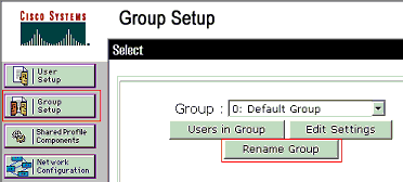
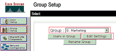
In order to create a group, choose Group Setup and rename the default group name.
-
In order to configure a group, choose the group from the list and click Edit Settings
-
Define the client IP address assignment as Assigned by AAA client pool. Enter the name of the IP address pool configured on the switch for this group clients.
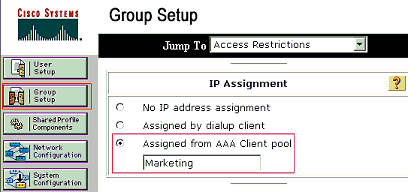
Note: Choose this option and type the AAA client IP pool name in the box, only if this user is to have the IP address assigned by an IP address pool configured on the AAA client.
Note: For IP Phones group configuration alone, skip the next step, step 4, and go to step 5.
-
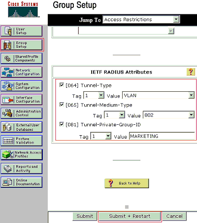
Define the Internet Engineering Task Force (IETF) attributes 64, 65 and 81 and then click Submit + Restart.
Make sure that the Tags of the Values are set to 1, as this example shows. Catalyst ignores any tag other than 1. In order to assign a user to a specific VLAN, you must also define attribute 81 with a VLAN name or VLAN number that corresponds.
Note: If you use the VLAN name, it should be exactly same as the one configured in the switch.
Note: Refer to RFC 2868: RADIUS Attributes for Tunnel Protocol Support
 for more information on these IETF attributes.
Note: In the initial configuration of the ACS server, IETF RADIUS attributes can fail to display in User Setup. In order to enable IETF attributes in user configuration screens, choose Interface configuration > RADIUS (IETF). Then, check attributes 64, 65, and 81 in the User and Group columns.
Note: If you do not define IETF attribute 81 and the port is a switch port in access mode, the client is assigned to the access VLAN of the port. If you have defined the attribute 81 for dynamic VLAN assignment and the port is a switch port in access mode, you need to issue the aaa authorization network default group radius command on the switch. This command assigns the port to the VLAN that the RADIUS server provides. Otherwise, 802.1x moves the port to the AUTHORIZED state after authentication of the user; but the port is still in the default VLAN of the port, and connectivity can fail.
Note: Next step is only applicable to the IP Phones group.
-
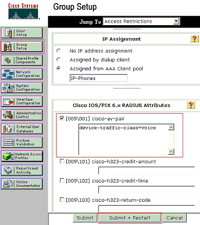
Configure the RADIUS server to send a Cisco Attribute-Value (AV) pair attribute to authorize a voice device. Without this, the switch treats the voice device as a data device. Define Cisco Attribute-Value (AV) pair attribute with a value of device-traffic-class=voice and click Submit + Restart.
User Setup
Complete these steps in order to add and configure a user.
-
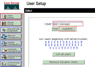
In order to add and configure users, choose User Setup. Enter the username and click Add/Edit
-
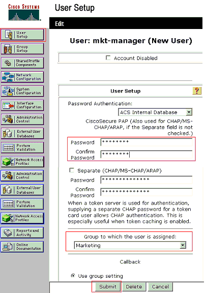
Define the user name, password and group for the user.
-
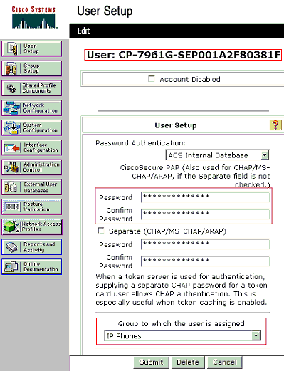
IP Phone uses its Device ID as the username and shared secret as the password for authentication. These values should match on the RADIUS server. For IP Phones P-1 and P-2 create usernames same as their Device ID and password same as the configured shared secret. See the Configure the IP Phones to Use 802.1x Authentication section for more information on the Device ID and Shared Secret on an IP Phone.
Configure the PC Clients to Use 802.1x Authentication
This example is specific to the Microsoft Windows XP Extensible Authentication Protocol (EAP) over LAN (EAPOL) client:
-
Choose Start > Control Panel > Network Connections, then right-click on your Local Area Connection and choose Properties.
-
Check Show icon in notification area when connected under the General tab.
-
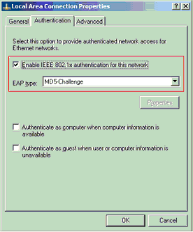
Under the Authentication tab, check Enable IEEE 802.1x authentication for this network.
-
Set the EAP type to MD5-Challenge, as this example shows:
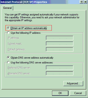
Complete these steps in order to configure the clients to obtain the IP address from a DHCP server.
-
Choose Start > Control Panel > Network Connections, then right-click on your Local Area Connection and choose Properties.
-
Under the General tab, click Internet Protocol (TCP/IP) and then Properties.
-
Choose Obtain an IP address automatically.
Configure the IP Phones to Use 802.1x Authentication
Complete these steps in order to configure the IP Phones for 802.1x authentication.
-
Press the Settings button in order to access the 802.1X Authentication settings and choose Security Configuration > 802.1X Authentication > Device Authentication.
-
Set the Device Authentication option to Enabled.
-
Press the Save softkey.
-
Choose 802.1X Authentication > EAP-MD5 > Shared Secret in order to set a password on the phone.
-
Enter the shared secret and press Save.
Note: The password must be between six and 32 characters, which consist of any combination of numbers or letters. That key is not active here message is shown and the password is not saved if this condition is not satisfied.
Note: If you disable 802.1X authentication or perform a factory reset on the phone, the previously configured MD5 shared secret is deleted.
Note: The other options, Device ID and Realm cannot be configured. Device ID is used as the username for 802.1x authentication. This is a derivative of the phone's model number and unique MAC address displayed in this format: CP-<model>-SEP-<MAC>. For example, CP-7970G-SEP001759E7492C. Refer to 802.1X Authentication Settings for more information.
Complete these steps in order to configure the IP Phone to obtain the IP address from a DHCP server.
-
Press the Settings button in order to access the Network Configuration settings and choose Network Configuration.
-
Unlock Network Configuration options. In order to unlock, press **#.
Note: Do not press **# in order to unlock options and then immediately press **# again in order to lock options. The phone interprets this sequence as **#**, which resets the phone. In order to lock options after you unlock them, wait at least 10 seconds before you press **# again.
-
Scroll to the DHCP Enabled option and press the Yes softkey in order to enable DHCP.
-
Press the Save softkey.
Verify
Use this section to confirm that your configuration works properly.
PC Clients
If you have correctly completed the configuration, the PC clients displays a popup prompt to enter a user name and password.
-
Click on the prompt, which this example shows:
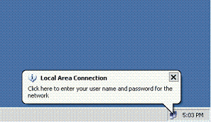
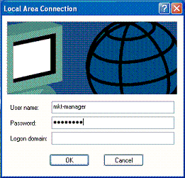
A user name and password entry window displays.
Note: MDA does not enforce the order of device authentication. But, for best results, Cisco recommends that a voice device is authenticated before a data device on an MDA enabled port.
-
Enter the user name and password.
-
If no error messages appear, verify connectivity with the usual methods, such as through access of the network resources and with ping.
Note: If this error appears, verify that the user name and password are correct:

IP Phones
802.1X Authentication Status menu in the IP Phones allows to monitor the authentication status.
-
Press the Settings button in order to access the 802.1X Authentication Real-Time Stats and choose Security Configuration > 802.1X Authentication Status.
-
The Transaction Status should be Authenticated. Refer to 802.1X Authentication Real-Time Status for more information.
Note: The authentication status can also be verified from Settings > Status > Status Messages.
Layer 3 Switch
If the password and user name appear to be correct, verify the 802.1x port state on the switch.
-
Look for a port status that indicates AUTHORIZED.
Cat-3560#show dot1x all summary
Interface       PAE     Client          Status
--------------------------------------------------------
Fa0/1           AUTH    0016.3633.339c  AUTHORIZED
                        0017.59e7.492c  AUTHORIZED
Fa0/2           AUTH    0014.5e94.5f99  AUTHORIZED
Fa0/3           AUTH    0011.858D.9AF9  AUTHORIZED
Fa0/4           AUTH    0016.6F3C.A342  AUTHORIZED
                        001a.2f80.381f  AUTHORIZED


Cat-3560#show dot1x interface fastEthernet 0/1 details

Dot1x Info for FastEthernet0/1
-----------------------------------
PAE                       = AUTHENTICATOR
PortControl               = AUTO
ControlDirection          = Both
HostMode                  = MULTI_DOMAIN
ReAuthentication          = Enabled
QuietPeriod               = 10
ServerTimeout             = 30
SuppTimeout               = 30
ReAuthPeriod              = 60 (Locally configured)
ReAuthMax                 = 2
MaxReq                    = 2
TxPeriod                  = 30
RateLimitPeriod           = 0
Auth-Fail-Vlan            = 6
Auth-Fail-Max-attempts    = 2
Guest-Vlan                = 6

Dot1x Authenticator Client List
-------------------------------
Domain                    = DATA
Supplicant                = 0016.3633.339c
    Auth SM State         = AUTHENTICATED
    Auth BEND SM State    = IDLE
Port Status               = AUTHORIZED
ReAuthPeriod              = 60
ReAuthAction              = Reauthenticate
TimeToNextReauth          = 29
Authentication Method     = Dot1x
Authorized By             = Authentication Server
Vlan Policy               = 4

Domain                    = VOICE
Supplicant                = 0017.59e7.492c
    Auth SM State         = AUTHENTICATED
    Auth BEND SM State    = IDLE
Port Status               = AUTHORIZED
ReAuthPeriod              = 60
ReAuthAction              = Reauthenticate
TimeToNextReauth          = 15
Authentication Method     = Dot1x
Authorized By             = Authentication Server
Verify the VLAN status after successful authentication.
Cat-3560#show vlan VLAN Name Status Ports ---- -------------------------------- --------- ------------------------------- 1 default active Fa0/5, Fa0/6, Fa0/7, Fa0/8 Fa0/9, Fa0/10, Fa0/11, Fa0/12 Fa0/13, Fa0/14, Fa0/15, Fa0/16 Fa0/17, Fa0/18, Fa0/19, Fa0/20 Fa0/21, Fa0/22, Fa0/23, Gi0/1 Gi0/2 2 SERVER active Fa0/24 3 VOICE active Fa0/1, Fa0/4 4 MARKETING active Fa0/1, Fa0/2 5 SALES active Fa0/3, Fa0/4 6 GUEST_and_AUTHFAIL active 1002 fddi-default act/unsup 1003 token-ring-default act/unsup 1004 fddinet-default act/unsup 1005 trnet-default act/unsup !--- Output suppressed. -
Verify the DHCP binding status after a successful authentication.
Router#show ip dhcp binding
IP address       Hardware address        Lease expiration        Type
172.16.3.2       0100.1759.e749.2c       Aug 24 2007 06:35 AM    Automatic
172.16.3.3       0100.1a2f.8038.1f       Aug 24 2007 06:43 AM    Automatic
172.16.4.2       0100.1636.3333.9c       Aug 24 2007 06:50 AM    Automatic
172.16.4.3       0100.145e.945f.99       Aug 24 2007 08:17 AM    Automatic
172.16.5.2       0100.166F.3CA3.42       Aug 24 2007 08:23 AM    Automatic
172.16.5.3       0100.1185.8D9A.F9       Aug 24 2007 08:51 AM    Automatic
The Output Interpreter Tool (registered customers only) (OIT) supports certain show commands. Use the OIT in order to view an analysis of show command output.
Troubleshoot
IP Phone Authentication fails
IP phone status displays Configuring IP or Registering if 802.1x authentication fails. Complete these steps in order to troubleshoot this issues:
-
Confirm that the 802.1x is enabled on the IP phone.
-
Verify that you have the Device ID entered on the authentication (RADIUS) server as the username.
-
Confirm that the shared secret is configured on the IP phone.
-
If the shared secret is configured, verify that you have the same shared secret entered on the authentication server.
-
Verify that you have properly configured the other required devices, for example, the switch and authentication server.
Related Information
- Configuring IEEE 802.1x Port-Based Authentication
- Configure the IP Phone to Use 802.1x Authentication
- Guidelines for the Deployment of Cisco Secure ACS for Windows NT/2000 Servers in a Cisco Catalyst Switch Environment
- RFC 2868: RADIUS Attributes for Tunnel Protocol Support

- IEEE 802.1x Authentication with Catalyst 6500/6000 Running Cisco IOS Software Configuration Example
- IEEE 802.1x Authentication with Catalyst 6500/6000 Running CatOS Software Configuration Example
- LAN Product Support Pages
- LAN Switching Support Page
- Technical Support & Documentation - Cisco Systems
Contact Cisco
- Open a Support Case

- (Requires a Cisco Service Contract)


 Feedback