Introduction
This document describes various possible combinations of different devices connected via EtherChannel.
Prerequisites
Requirements
Cisco recommends that you have knowledge of these topics:
- Cisco Switching and Catalyst Operations
- STP
- EtherChannel Concepts
- Cisco Layer 2 Protocols
Components Used
The information in this document is based on but not limited to:
- Cisco Catalyst switches.
- Cisco Nexus Switches
- HA with Virtual Switch Link (VSL), VSS,Stacking, and vPC
- EtherChannel

Note: This document is not bound to a specific software version running on Cisco devices.
The information in this document was created from the devices in a specific lab environment. If your network is live, ensure you understand the potential impact of any physical layer connection change.
Background Information
This document is useful for understanding different recommended ways to build EtherChannel between Cisco devices or a Cisco device and a Non-Cisco device.
Explanation
An EtherChannel consists of individual interface links that must have the same logical and physical properties. These links are bundled together as a single logical link which is nothing but the EtherChannel.
For example,
From Link perspective: GigabitEthernet interfaces can be bundled together but GigabitEthernet Interface cannot be bundled with FastEthernet or TenGigabitEthernet and vice versa.
From a Device perspective: EtherChannel can be formed between two devices, i.e., two switches or a switch and a multilayer switch or a switch and a server, etc.
Also, it can be formed between two logical devices i.e., two switch stacks, or a switch and a switch stack, an OR switch and a vPC, etc.
Multiple EtherChannel Exhibits
Design 1. EtherChannel between Two Single Switches
 Design 1. EtherChannel between Two Single Switches
The exhibits of EtherChannel shown are the basic design of EtherChannel consisting of two links between two switches.
Design 2. EtherChannel with 8 Links
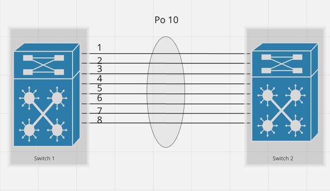 Design 2. EtherChannel with 8 Links
The exhibits of EtherChannel shown above is the basic design of EtherChannel consisting of eight links between two switches which is the maximum supported active links (As per PAGP).
EtherChannel might have in total 16 links where 8 are active and the other 8 are on hot standby (ss per LACP).
Design 3. EtherChannel between Stack and a Single Switch. Variation 1.
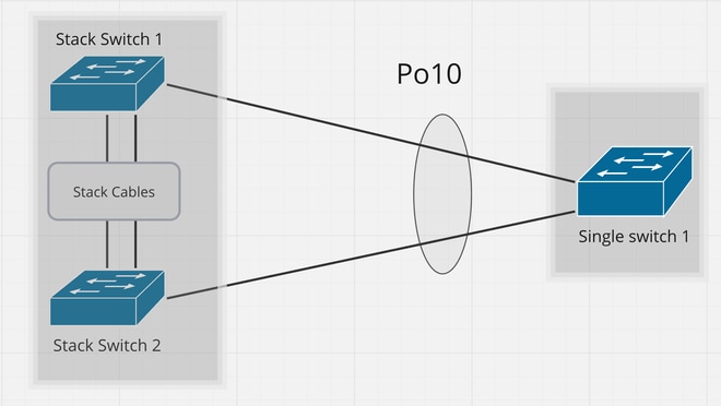 Design 3. EtherChannel between Stack and a Single Switch. Variation 1
This design shows the EtherChannel connection in a stacked environment. Stack Switch 1 and Stack Switch 2 are two different switches but logically act as a Single Switch entity running StackWise as a protocol.
Design 4: EtherChannel between two Stacks. Variation 1.
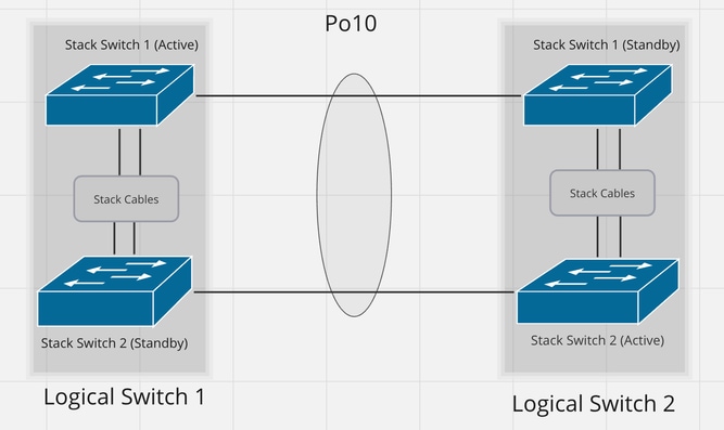 Design 4: EtherChannel between two Stacks. Variation 1
This design demonstrates the EtherChannel connection between two Stacked Switches.
Logical switch 1 on the left side consists of two physical switches i.e., stack switch 1 and stack switch 2, connected over stack cables and similarly on the right side there is a logical switch 2.
Here in this case, EtherChannel is formed between logical switch 1 and logical switch 2.
EtherChannel created over here is in between two single logical entities, one entity is logical switch 1 and the other is logical switch 2.
Design 5: EtherChannel between two VSS / VSL Setups
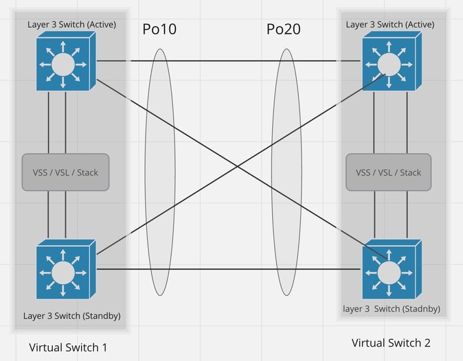 Design 5: EtherChannel between two VSS / VSL Setups
This design demonstrates EtherChannel connection between two VSS/VSL Setup Switches. Left Top Switch acts as a Virtual Active switch and Left bottom switch act as a Virtual Stanby Switch are bind together via VSS/VSL protocol which as a result acts as one logical switch. Same way the right Virtual setup has also been designed.
The EtherChannel shown here is a perfect example of full redundancy between two VSS/SVL setups.
Design 6: EtherChannel between Stack and a Single Switch. Variation 2.
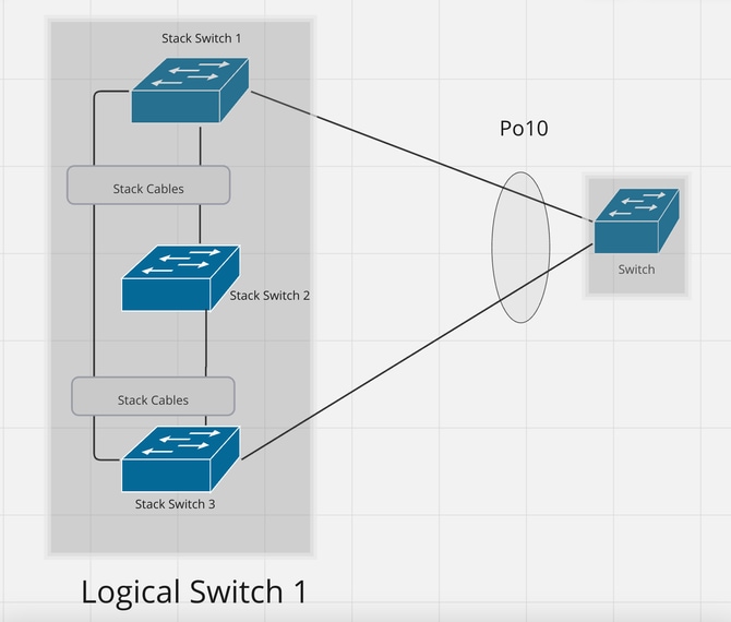 Design 6: EtherChannel between Stack and a Single Switch. Variation 2
This design demonstrates EtherChannel between the Logical switch on the Left side and the switch on the Right Side.
Logical Switch 1 is acting as a single switch but consists of a stack of three physical Switches i.e., Switch 1, Switch 2, and Switch 3.
It's not mandatory to have an EtherChannel member link connected to each switch in the stack.
Design 7: EtherChannel between two Stacks. Variation 2.
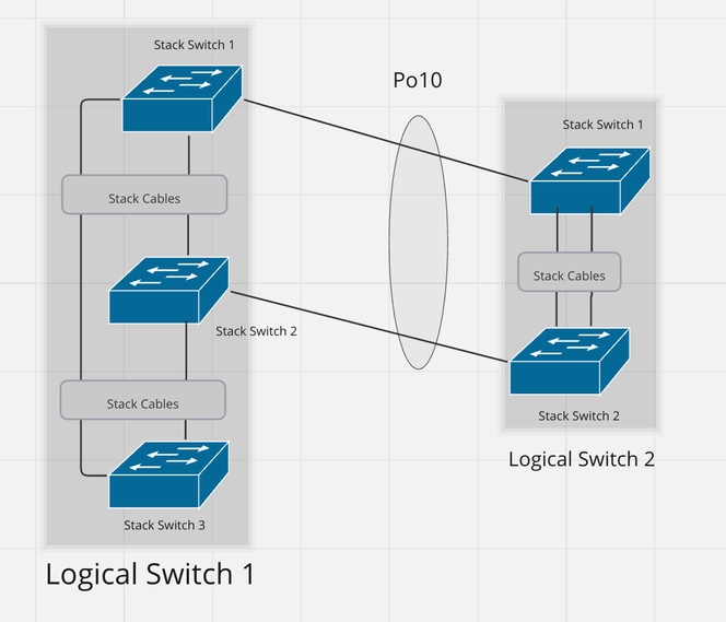 Design 7: EtherChannel between two Stacks. Variation 2
This is the variant of the previous design but in this design, we have the stack on the right side too.
Design 8: EtherChannel with vPC
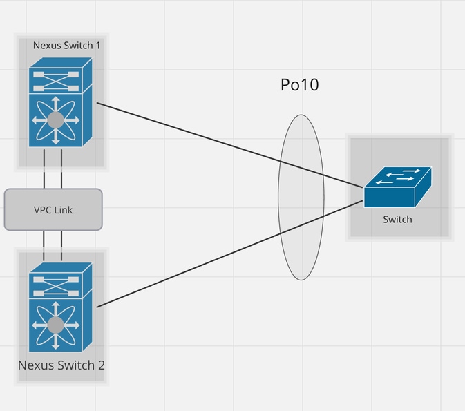 Design 8: EtherChannel with vPC
In this design, on the left side, there are two physically and logically separated Nexus devices, Nexus Switch 1 and Nexus Switch 2.
These Nexus switches are running the Virtual Port Channel (vPC) protocol in such a way that the peer device (in this case its switch on the Right Side) perceives the Nexus setup as a single switch.
vPC is a feature available for Nexus switches. Using EtherChannel links, you can interconnect two Nexus switches that are running the vPC feature and configuration. In this way, you can create a single logical node.
vPC ties two Nexus switches together by spoofing Layer 2, including STP BPDU and FHRP (First Hop Routing Protocol — HSRP, VRRP, GLBP).
Nexus is mainly used for data centers and VSS for campus environments. The maximum number of devices you can use for both vPC and VSS is 2. As far as the difference, VSS has one control plane vs vPC has 2 different ones. With VSS you eliminate the use of VRRP, HSRP, etc. With VPC you still have to use one HSRP or VRRP.
vPC is a virtualization technology, which allows links that are physically connected to two different Cisco Nexus Series devices to appear as a single port channel to a third endpoint.
Design 9:EtherChannel with NIC Teaming
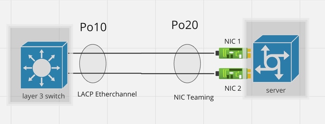 Design 9:EtherChannel with NIC Teaming
NIC Teaming allows you to combine multiple physical and virtual network interfaces into a single logical virtual adapter called NIC Team.
This design demonstrates an EtherChannel connection between the switch and the Server.
In this case from the switch end, the EtherChannel can be configured either with ON Mode or LACP Active/Passive Mode; all depending on the protocol running from the peer side.
Design 10: EtherChannel with Firewall in HA Mode
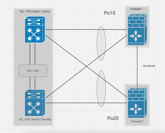 Design 10: EtherChannel with Firewall in HA Mode
This design demonstrates the EtherChannel connection between VSS/VSL Setup Switches and the Firewall in HA Mode.
The Left Top Switch acts as an Active switch and the Left bottom switch acts as a Standby Switch are bound together via VSS/VSL protocol. As a result, they both act as a single logical switch.
On the Right side, there are logically and Physically separated two Firewalls generally acting as Active and Standby. To achieve redundancy, from each Firewall there should be a link connected to both Switches of VSS / VSL setups. The redundancy is achieved by two EtherChannels; PortChannel 10 and PortChannel 20 in this case. PortChannel 10 consists of two links both starting from Firewall 1 and terminating to VSS/ VSL switch Active and Standby respectively and the same way PortChannel 20 starts from Firewall 2.
Design 11. Unsupported Desing with Redundant Firewall
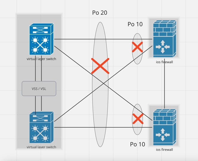 Design 11. Unsupported Desing with Redundant Firewall
This design is unsupported. The reason is the Port-Channel configuration on the switch side is incorrect and leads to a traffic block on the standby device. Such design is only supported when you configure ASA or FTD in Cluster Spanned mode.
For clarification, please refer to the previous design.
Design 12. Unsupported Design with FHRP-configured Routers
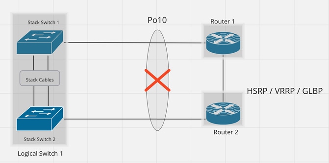 Design 12. Unsupported Design with FHRP-configured Routers
This design is unsupported as it violates the basic design principle of EtherChannel.
In this design, on the left side both the switches act as a Single Logical Switch oppositely on the Right Side the Routers are physically and logically separated.
Router 1 and Router 2 are coupled with FHRP protocol and it does not provide any support for EtherChannel redundancy.
So it's not legitimate and supported to bundle links originating from these routers under a single EtherChannel.

Note: In the case of Nexus vPC under certain circumstances, FHRP, and EtherChannels both supported.