MPLS VPN over ATM: with OSPF on the Customer Side (without Area 0)
Available Languages
Contents
Introduction
This document provides a sample configuration of a Multiprotocol Label Switching (MPLS) VPN over ATM when Open Shortest Path First (OSPF) is present on the customer side, without area 0.
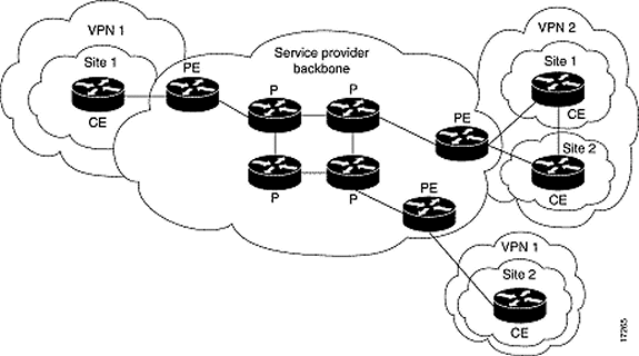
The Virtual Private Network (VPN) feature, when used with MPLS, allows several sites to transparently interconnect through the network of a service provider. One service provider network can support several different IP VPNs. Each of these appears to its users as a private network, separate from all other networks. Within a VPN, each site can send IP packets to any other site in the same VPN.
Prerequisites
Requirements
Each VPN is associated with one or more VPN routing or forwarding instances (VRFs). A VRF consists of an IP routing table, a derived Cisco express forwarding (CEF), table and a set of interfaces that use this forwarding table.
The router maintains a separate routing and CEF table for each VRF. With this, information cannot be sent outside the VPN but the same subnet can be used in several VPNs without duplicate IP address problems.
The router that uses Border Gateway Protocol (BGP) distributes the VPN routing information with the BGP extended communities.
For more information in regard to the propagation of updates through a VPN, refer to these URLs:
Hardware and Software Versions
These letters represent the different types of routers and switches used:
-
P : Provider core router
-
PE : Provider edge router
-
CE : Customer edge router
-
C : Customer router
We developed and tested the configuration with these software and hardware versions:
-
PE routers:
-
Software: Cisco IOS® Software Release 12.1(3)T . The MPLS VPN features appear in Release 12.0(5)T. The OSPF as PE-CE routing protocol appears in Release 12.0(7)T.
-
Hardware: The Cisco 3660 or 7206 routers. For details of other hardware you can use, refer to the Designing MPLS for ATM guide.
-
-
CE routers: Use any router that is able to exchange routing information with its PE router.
-
P routers and switches: The MPLS VPN integration function resides only on the edge of the MPLS network, so use any MPLS-capable switch. In the sample configuration, the MPLS cloud is composed of an 8540 MSR and a LightStream 1010. If you use the LightStream 1010, we recommend that you use software version WA4.8d or higher. You can also use other ATM switches, such as the Cisco BPX 8650 or MGX 8850 in the ATM core network.
Conventions
This diagram shows a typical configuration that uses these conventions:

Refer to Cisco Technical Tips Conventions for more information on document conventions.
OSPF Background Information
Traditionally, an elaborate OSPF network consists of a backbone area (area 0) and a number of areas connected to this backbone through an area border router (ABR).
With an MPLS backbone for VPN with OSPF on the customer site, you can introduce a third level in the hierarchy of the OSPF model. This third level is called the MPLS VPN super backbone.
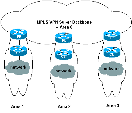
In simple cases, the MPLS VPN super backbone is combined with the traditional area 0 backbone. This means that there is no area 0 backbone on the customer network since the MPLS VPN super backbone plays the same role as the area 0 backbone. This is shown in this diagram:

This diagram illustrates this information:
-
The provider-edge (PE) routers are ABR and autonomous system boundary router (ASBR) routers.
-
The customer-edge (CE) routers are simple OSPF routers.
-
The VPN information is transported through BGP extended communities from PEs to other PEs and is re-injected into the OSPF areas as Summary Network (type 3) link-state advertisements (LSAs).
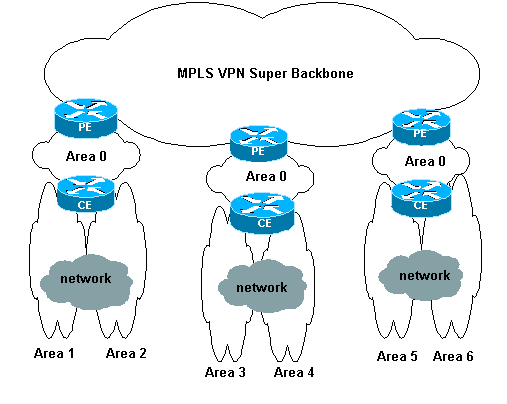
The MPLS VPN super backbone also enables customers to use multiple area 0 backbones on their sites. Each site can have a separate area 0 as long as it is connected to the MPLS VPN super backbone. The result is the same as with a partitioned area 0 backbone. This is shown in this diagram:

In this case, these things occur:
-
The PE routers are ABR and ASBR routers.
-
The CE routers are ABR routers.
-
The LSAs that contain VPN information are transported with BGP extended communities from PEs to other PEs. In Summary Network (type 3) LSAs, information is transported between PEs and CEs.
This sample configuration is based on the first setup shown. You can find a sample configuration that uses the second setup in MPLS VPN over ATM: with OSPF on the Customer Side (with Area 0).
OSPF information is transported with BGP extended community attributes (which include one that identifies the OSPF network). Each VPN must have its own OSPF process. In order to specify this, you can use this command:
router ospf <process ID> vrf <VPN routing/forwarding instance name>
Configuration Procedure
In this section, you are presented with the information to configure the features described in this document.
Note: Use the Command Lookup Tool (registered customers only) to find more information on the commands used in this document.
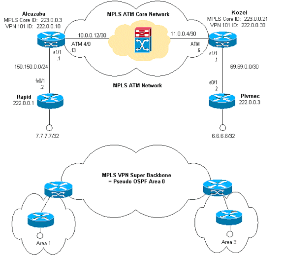
Network Diagram
This document uses this network setup:

The Cisco IOS documentation (MPLS Virtual Private Networks) also describes this configuration procedure.
Configuration Procedure Part I
Make sure that ip cef is enabled. If you use a Cisco 7500 Router, you must ensure that ip cef distributed is enabled. On the PEs, once MPLS is set up, perform these tasks:
-
Create one VRF for each VPN connected with the ip vrf <VPN routing/forwarding instance name> command. When you do this:
-
Specify the correct route distinguisher used for that VPN. This is used to extend the IP address so that you can identify the VPN to which it belongs.
rd <VPN route distinguisher>
-
Set up the import and export properties for the BGP extended communities. These are used to filter the import and export process.
route-target [export|import|both] <target VPN extended community>
-
-
Configure the forwarding details for the respectives interfaces with this command:
ip vrf forwarding <table name>
Remember to set up the IP address after you do this.
-
Dependent upon the PE-CE routing protocol that you use, you must now do one or more of these:
-
Configure the static routes:
ip route vrf vrf-name prefix mask [next-hop-address] [interface {interface-number}] -
Configure the RIP with this command:
address-family ipv4 vrf <VPN routing/forwarding instance name>
Once you have done this part, enter the normal RIP configuration commands.
Note: This is only applied to the forwarding interfaces for the current VRF.
Note: You have to redistribute the correct BGP into RIP. When you do this, also remember to specify the metric that is used.
-
Declare the BGP neighbor information.
-
Configure the OSPF with the new IOS command:
router ospf <process ID> vrf <VPN routing/forwarding instance name>
Note: This is only applied to the forwarding interfaces for the current VRF.
Note: You have to redistribute the correct BGP into OSPF. When you do this, also remember to specify the metric that is used.
Note: Once you attribute the OSPF process to a VRF, this process number is always used for this particular VRF. This applies even if you do not specify it in the command line.
-
Configuration Procedure Part II
Configure BGP between the PE routers. There are several ways to configure BGP, such as the use of the route reflector or confederation methods. The method used here – direct neighbor configuration – is the simplest and least scalable.
-
Declare the different neighbors.
-
Enter the address-family ipv4 vrf <VPN routing/forwarding instance name> for each VPN present at this PE router. Carry out one or more of these steps, as necessary:
-
Redistribute the static routing information.
-
Redistribute the RIP routing informations.
-
Redistribute the OSPF routing information.
-
Activate BGP neighbors with the CE routers.
-
-
Enter the address-family vpnv4 mode, and perform these tasks:
-
Activate the neighbors.
-
Specify that extended community must be used. This is mandatory.
-
Configurations
Note: Only the relevant parts of the output are included here.
| Alcazaba |
|---|
ip cef ! ip vrf vpn1 rd 1:101 route-target export 1:101 route-target import 1:101 ! interface Loopback0 ip address 223.0.0.3 255.255.255.255 ! interface Loopback1 ip vrf forwarding vpn1 ip address 222.0.0.10 255.255.255.255 ! interface Ethernet1/1 ip vrf forwarding vpn1 ip address 150.150.0.1 255.255.255.0 no ip mroute-cache ! interface ATM4/0 no ip address no ip mroute-cache atm sonet stm-1 no atm ilmi-keepalive ! interface ATM4/0.1 tag-switching ip address 10.0.0.13 255.255.255.252 tag-switching atm vpi 2-4 tag-switching ip ! router ospf 1 log-adjacency-changes network 10.0.0.0 0.0.0.255 area 0 network 150.150.0.0 0.0.0.255 area 0 network 223.0.0.3 0.0.0.0 area 0 ! router ospf 2 vrf vpn1 log-adjacency-changes redistribute bgp 1 metric-type 1 subnets network 150.150.0.0 0.0.0.255 area 1 network 222.0.0.0 0.0.0.255 area 1 ! router bgp 1 neighbor 223.0.0.21 remote-as 1 neighbor 223.0.0.21 update-source Loopback0 ! address-family ipv4 vrf vpn1 redistribute ospf 2 no auto-summary no synchronization exit-address-family ! address-family vpnv4 neighbor 223.0.0.21 activate neighbor 223.0.0.21 send-community extended exit-address-family ! |
| Kozel |
|---|
! ip cef ! ip vrf vpn1 rd 1:101 route-target export 1:101 route-target import 1:101 ! interface Loopback0 ip address 223.0.0.21 255.255.255.255 ! interface Loopback1 ip vrf forwarding vpn1 ip address 222.0.0.30 255.255.255.255 ! interface Ethernet1/1 ip vrf forwarding vpn1 ip address 69.69.0.1 255.255.255.252 no ip mroute-cache tag-switching ip ! interface ATM4/0 no ip address no atm scrambling cell-payload no atm ilmi-keepalive pvc qsaal 0/5 qsaal ! pvc ilmi 0/16 ilmi ! ! interface ATM4/0.1 tag-switching ip address 11.0.0.6 255.255.255.252 tag-switching atm vpi 2-4 tag-switching ip ! router ospf 1 log-adjacency-changes network 11.0.0.0 0.0.0.255 area 0 network 223.0.0.21 0.0.0.0 area 0 mpls traffic-eng router-id Loopback0 mpls traffic-eng area 0 ! router ospf 2 vrf vpn1 log-adjacency-changes redistribute bgp 1 metric-type 1 subnets network 69.69.0.0 0.0.0.255 area 3 network 222.0.0.0 0.0.0.255 area 3 ! router bgp 1 neighbor 223.0.0.3 remote-as 1 neighbor 223.0.0.3 update-source Loopback0 neighbor 223.0.0.11 remote-as 1 neighbor 223.0.0.11 update-source Loopback0 ! address-family ipv4 vrf vpn1 redistribute ospf 2 no auto-summary no synchronization exit-address-family ! address-family vpnv4 neighbor 223.0.0.3 activate neighbor 223.0.0.3 send-community extended neighbor 223.0.0.11 activate neighbor 223.0.0.11 send-community extended exit-address-family ! |
| Rapid |
|---|
! interface Loopback0 ip address 222.0.0.1 255.255.255.255 ! interface Loopback2 ip address 7.7.7.7 255.255.255.0 ! interface FastEthernet0/1 ip address 150.150.0.2 255.255.255.0 duplex auto speed auto ! router ospf 1 network 7.7.7.7 0.0.0.0 area 1 network 150.150.0.0 0.0.0.255 area 1 network 222.0.0.1 0.0.0.0 area 1 ! |
| Pivrnec |
|---|
! interface Loopback0 ip address 222.0.0.3 255.255.255.255 ! interface Loopback1 ip address 6.6.6.6 255.255.255.255 ! interface FastEthernet0/1 ip address 69.69.0.2 255.255.255.252 duplex auto speed auto ! router ospf 1 log-adjacency-changes network 6.6.6.6 0.0.0.0 area 3 network 69.69.0.0 0.0.0.255 area 3 network 222.0.0.3 0.0.0.0 area 3 ! |
Verify
Show Commands
The Output Interpreter Tool (registered customers only) (OIT) supports certain show commands. Use the OIT to view an analysis of show command output.
-
show ip route vrf <VPN routing or forwarding instance name>
-
show ip bgp vpnv4 vrf <VPN routing or forwarding instance name> <A.B.C.D>
-
show ip ospf <process ID number>
-
show ip ospf <process ID number> interface
-
show ip ospf <process ID number> database
-
show tag-switching forwarding-table vrf <VPN routing or forwarding instance name>
This command shows the VRF for a particular VPN at the PE router:
Alcazaba#show ip route vrf vpn1
Codes: C - connected, S - static, I - IGRP, R - RIP, M - mobile, B - BGP
       D - EIGRP, EX - EIGRP external, O - OSPF, IA - OSPF inter area
       N1 - OSPF NSSA external type 1, N2 - OSPF NSSA external type 2
       E1 - OSPF external type 1, E2 - OSPF external type 2, E - EGP
       i - IS-IS, L1 - IS-IS level-1, L2 - IS-IS level-2, ia - IS-IS inter area
       * - candidate default, U - per-user static route, o - ODR
       P - periodic downloaded static route

Gateway of last resort is not set

     69.0.0.0/30 is subnetted, 1 subnets
B       69.69.0.0 [200/0] via 223.0.0.21, 00:19:39
     222.0.0.0/32 is subnetted, 4 subnets
B       222.0.0.30 [200/0] via 223.0.0.21, 00:19:39
C       222.0.0.10 is directly connected, Loopback1
B       222.0.0.3 [200/11] via 223.0.0.21, 00:20:39
O       222.0.0.1 [110/11] via 150.150.0.2, 00:20:59, Ethernet1/1
     6.0.0.0/32 is subnetted, 1 subnets
B       6.6.6.6 [200/11] via 223.0.0.21, 00:20:39
     7.0.0.0/32 is subnetted, 1 subnets
O       7.7.7.7 [110/11] via 150.150.0.2, 00:21:00, Ethernet1/1
     150.150.0.0/24 is subnetted, 1 subnets
C       150.150.0.0 is directly connected, Ethernet1/1
You can also display the BGP information for a particular VRF with the show ip bgp vpnv4 vrf command. The PE-PE results from the internal BGP (IBGP) are indicated by an i.
Alcazaba#show ip bgp vpnv4 vrf vpn1
BGP table version is 21, local router ID is 223.0.0.3
Status codes: s suppressed, d damped, h history, * valid, > best, i - internal
Origin codes: i - IGP, e - EGP, ? - incomplete

   Network          Next Hop            Metric LocPrf Weight Path
Route Distinguisher: 1:101 (default for vrf vpn1)
*>i6.6.6.6/32       223.0.0.21              11    100      0 ?
*> 7.7.7.7/32       150.150.0.2             11         32768 ?
*>i69.69.0.0/30     223.0.0.21               0    100      0 ?
*> 150.150.0.0/24   0.0.0.0                  0         32768 ?
*> 222.0.0.1/32     150.150.0.2             11         32768 ?
*>i222.0.0.3/32     223.0.0.21              11    100      0 ?
*> 222.0.0.10/32    0.0.0.0                  0         32768 ?
*>i222.0.0.30/32    223.0.0.21               0    100      0 ?
You can check the details of an entry. In order to show this, the route distinguisher is "1:101."
Alcazaba#show ip bgp vpnv4 vrf vpn1 6.6.6.6
BGP routing table entry for 1:101:6.6.6.6/32, version 28
Paths: (1 available, best #1, table vpn1)
  Not advertised to any peer
  Local
    223.0.0.21 (metric 4) from 223.0.0.21 (223.0.0.21)
      Origin incomplete, metric 11, localpref 100, valid, internal, best
      Extended Community: RT:1:101 OSPF RT:3:2:0

Alcazaba#show ip bgp vpnv4 vrf vpn1 7.7.7.7
BGP routing table entry for 1:101:7.7.7.7/32, version 20
Paths: (1 available, best #1, table vpn1)
  Advertised to non peer-group peers:
  223.0.0.21
  Local
    150.150.0.2 from 0.0.0.0 (223.0.0.3)
      Origin incomplete, metric 11, localpref 100, weight 32768, valid, sourced, best
      Extended Community: RT:1:101 OSPF RT:1:2:0
The show ip route command on a CE router is the primary means to verify the routing tables:
rapid#show ip route
Codes: C - connected, S - static, I - IGRP, R - RIP, M - mobile, B - BGP
       D - EIGRP, EX - EIGRP external, O - OSPF, IA - OSPF inter area
       N1 - OSPF NSSA external type 1, N2 - OSPF NSSA external type 2
       E1 - OSPF external type 1, E2 - OSPF external type 2, E - EGP
       i - IS-IS, L1 - IS-IS level-1, L2 - IS-IS level-2, ia - IS-IS inter area
       * - candidate default, U - per-user static route, o - ODR
       P - periodic downloaded static route

Gateway of last resort is not set

     69.0.0.0/30 is subnetted, 1 subnets
O IA    69.69.0.0 [110/11] via 150.150.0.1, 00:20:25, FastEthernet0/1
     222.0.0.0/32 is subnetted, 4 subnets
O IA    222.0.0.30 [110/11] via 150.150.0.1, 00:20:25, FastEthernet0/1
O       222.0.0.10 [110/11] via 150.150.0.1, 00:21:46, FastEthernet0/1
O IA    222.0.0.3 [110/21] via 150.150.0.1, 00:21:25, FastEthernet0/1
C       222.0.0.1 is directly connected, Loopback0
     6.0.0.0/32 is subnetted, 1 subnets
O IA    6.6.6.6 [110/21] via 150.150.0.1, 00:21:25, FastEthernet0/1
     7.0.0.0/24 is subnetted, 1 subnets
C       7.7.7.0 is directly connected, Loopback2
     10.0.0.0/22 is subnetted, 1 subnets
C       10.200.8.0 is directly connected, FastEthernet0/0
     150.150.0.0/24 is subnetted, 1 subnets
C       150.150.0.0 is directly connected, FastEthernet0/1
S    158.0.0.0/8 is directly connected, Null0
OSPF-Specific Commands
You can use all of the show ip ospf commands. When you do this, remember to indicate the process ID. We have marked the most important parts of the output below in italicized text.
OSPF LSAs of type 9, 10 and 11 (also known as Opaque LSAs) are used to engineer traffic.
Commands for a PE Router
Alcazaba#show ip ospf 2
 Routing Process "ospf 2" with ID 222.0.0.10
 Supports only single TOS(TOS0) routes
 Supports opaque LSA
 Connected to MPLS VPN super backbone
 It is an area border and autonomous system boundary router
 Redistributing External Routes from,
    bgp 1, includes subnets in redistribution
 SPF schedule delay 5 secs, Hold time between two SPFs 10 secs
 Minimum LSA interval 5 secs. Minimum LSA arrival 1 secs
 Number of external LSA 0. Checksum Sum 0x0
 Number of opaque AS LSA 0. Checksum Sum 0x0
 Number of DCbitless external and opaque AS LSA 0
 Number of DoNotAge external and opaque AS LSA 0
 Number of areas in this router is 1. 1 normal 0 stub 0 nssa
 External flood list length 0
    Area 1
        Number of interfaces in this area is 2
        Area has no authentication
        SPF algorithm executed 4 times
        Area ranges are
        Number of LSA 7. Checksum Sum 0x420BE
        Number of opaque link LSA 0. Checksum Sum 0x0
        Number of DCbitless LSA 0
        Number of indication LSA 0
        Number of DoNotAge LSA 0
        Flood list length 0

Alcazaba#show ip ospf 2 interface
Loopback1 is up, line protocol is up
  Internet Address 222.0.0.10/32, Area 1
  Process ID 2, Router ID 222.0.0.10, Network Type LOOPBACK, Cost: 1
  Loopback interface is treated as a stub Host
Ethernet1/1 is up, line protocol is up
  Internet Address 150.150.0.1/24, Area 1
  Process ID 2, Router ID 222.0.0.10, Network Type BROADCAST, Cost: 10
  Transmit Delay is 1 sec, State DR, Priority 1
  Designated Router (ID) 222.0.0.10, Interface address 150.150.0.1
  Backup Designated router (ID) 222.0.0.1, Interface address 150.150.0.2
  Timer intervals configured, Hello 10, Dead 40, Wait 40, Retransmit 5
    Hello due in 00:00:07
  Index 1/1, flood queue length 0
  Next 0x0(0)/0x0(0)
  Last flood scan length is 2, maximum is 3
  Last flood scan time is 0 msec, maximum is 0 msec
  Neighbor Count is 1, Adjacent neighbor count is 1
    Adjacent with neighbor 222.0.0.1  (Backup Designated Router)
  Suppress hello for 0 neighbor(s)

Alcazaba#show ip ospf 2 database

            OSPF Router with ID (222.0.0.10) (Process ID 2)

                Router Link States (Area 1)

Link ID         ADV Router      Age         Seq#       Checksum Link count
222.0.0.1       222.0.0.1       1364        0x80000013 0x7369   3
222.0.0.10      222.0.0.10      1363        0x80000002 0xFEFE   2

                Net Link States (Area 1)

Link ID         ADV Router      Age         Seq#       Checksum
150.150.0.1     222.0.0.10      1363        0x80000001 0xEC6D

                Summary Net Link States (Area 1)

Link ID         ADV Router      Age         Seq#       Checksum
6.6.6.6         222.0.0.10      1328        0x80000001 0x4967
69.69.0.0       222.0.0.10      1268        0x80000001 0x2427
222.0.0.3       222.0.0.10      1328        0x80000001 0xEEF7
222.0.0.30      222.0.0.10      1268        0x80000001 0x7B5A
Commands for a CE Router
rapid#show ip ospf interface
FastEthernet0/1 is up, line protocol is up
  Internet Address 150.150.0.2/24, Area 1
  Process ID 1, Router ID 222.0.0.1, Network Type BROADCAST, Cost: 10
  Transmit Delay is 1 sec, State BDR, Priority 1
  Designated Router (ID) 222.0.0.10, Interface address 150.150.0.1
  Backup Designated router (ID) 222.0.0.1, Interface address 150.150.0.2
  Timer intervals configured, Hello 10, Dead 40, Wait 40, Retransmit 5
    Hello due in 00:00:04
  Index 2/2, flood queue length 0
  Next 0x0(0)/0x0(0)
  Last flood scan length is 1, maximum is 2
  Last flood scan time is 0 msec, maximum is 0 msec
  Neighbor Count is 1, Adjacent neighbor count is 1
    Adjacent with neighbor 222.0.0.10  (Designated Router)
  Suppress hello for 0 neighbor(s)
Loopback0 is up, line protocol is up
  Internet Address 222.0.0.1/32, Area 1
  Process ID 1, Router ID 222.0.0.1, Network Type LOOPBACK, Cost: 1
  Loopback interface is treated as a stub Host
Loopback2 is up, line protocol is up
  Internet Address 7.7.7.7/24, Area 1
  Process ID 1, Router ID 222.0.0.1, Network Type LOOPBACK, Cost: 1
  Loopback interface is treated as a stub Host

rapid#show ip ospf database

       OSPF Router with ID (222.0.0.1) (Process ID 1)

                Router Link States (Area 1)

Link ID         ADV Router      Age         Seq#       Checksum Link count
222.0.0.1       222.0.0.1       1350        0x80000013 0x7369   3
222.0.0.10      222.0.0.10      1350        0x80000002 0xFEFE   2

                Net Link States (Area 1)

Link ID         ADV Router      Age         Seq#       Checksum
150.150.0.1     222.0.0.10      1351        0x80000001 0xEC6D

                Summary Net Link States (Area 1)

Link ID         ADV Router      Age         Seq#       Checksum
6.6.6.6         222.0.0.10      1316        0x80000001 0x4967
69.69.0.0       222.0.0.10      1256        0x80000001 0x2427
222.0.0.3       222.0.0.10      1316        0x80000001 0xEEF7
222.0.0.30      222.0.0.10      1256        0x80000001 0x7B5A

Alcazaba#show tag-switching forwarding-table vrf vpn1
Local  Outgoing    Prefix            Bytes tag  Outgoing   Next Hop
tag    tag or VC   or Tunnel Id      switched   interface
24     Aggregate   222.0.0.10/32[V]  0
25     Aggregate   150.150.0.0/24[V] 0
27     Untagged    7.7.7.7/32[V]     1710       Et1/1      150.150.0.2
28     Untagged    222.0.0.1/32[V]   0          Et1/1      150.150.0.2
MPLS Labels
You can check the label stack used for a particular route:
Alcazaba#show tag-switching forwarding-table vrf vpn1 6.6.6.6 detail
Local  Outgoing    Prefix            Bytes tag  Outgoing   Next Hop
tag    tag or VC   or Tunnel Id      switched   interface
None   2/41        6.6.6.6/32        0          AT4/0.1    point2point
        MAC/Encaps=4/12, MTU=4466, Tag Stack{2/41(vcd=10) 16}
        000A8847 0000A00000010000
Debugging Output
Here is an excerpt from the route exchange debugging information. This shows how a particular route is imported.
Alcazaba#debug ip bgp vpnv4 import
Tag VPN import processing debugging is on
*Aug  5 05:10:09.283: vpn: Start import processing for: 1:101:222.0.0.3
*Aug  5 05:10:09.283: vpn: Import check for vpn1; flags mtch, impt
*Aug  5 05:10:09.283: vpn: Import for vpn1 permitted; import flags mtch, impt
*Aug  5 05:10:09.283: vpn: Same RD import for vpn1
*Aug  5 05:10:09.283: vpn: 1:101:222.0.0.3 (ver 29), imported as:
*Aug  5 05:10:09.283: vpn: 1:101:222.0.0.3 (ver 29)
*Aug  5 05:10:09.287: VPN: Scanning for import check is done.
Testing Output
You can now use ping to test that everything is fine:
Pivrnec#ping 7.7.7.7

Type escape sequence to abort.
Sending 5, 100-byte ICMP Echos to 7.7.7.7, timeout is 2 seconds:
!!!!!
Success rate is 100 percent (5/5), round-trip min/avg/max = 1/2/4 ms
The traceroute command displays this output:
Pivrnec#traceroute 7.7.7.7

Type escape sequence to abort.
Tracing the route to 7.7.7.7

  1 69.69.0.1 0 msec 0 msec 0 msec
  2 150.150.0.1 0 msec 0 msec 20 msec
  3 150.150.0.2 0 msec 0 msec *
The MLPS hosts are not here because they do not see the IP header. The MPLS hosts only check the inbound label or interface and then forward it.
The operation on the IP Time To Live (TTL) field is only carried out on the edge LSR. The hop count shown is less than the actual hop count.
Related Information
Revision History
| Revision | Publish Date | Comments |
|---|---|---|
1.0 |
05-Jun-2005 |
Initial Release |
Contact Cisco
- Open a Support Case

- (Requires a Cisco Service Contract)
 Feedback